Table of Contents
Advertisement
Quick Links
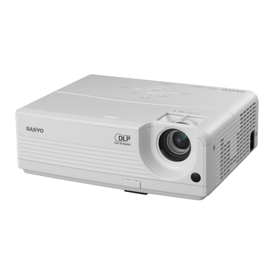
SERVICE MANUAL
Product code
1 122 418 00
(KA7A)
1 122 419 00
(LA7A)
1 122 419 02
(LA7C)
Multimedia Projector
Match the Chassis No. on the unit's back cover with the
Chassis No. in the Service Manual.
If the Original Version Service Manual Chassis No. does
not match the unit's, additional Service Literature is re-
quired. You must refer to "Notices" to the Original Service
Manual prior to servicing the unit.
FILE NO.
Model No. PdG-dSu20N
U.S.A, Canada,
PdG-dSu20e
Europe, Asia
PdG-dSu20B
U.K.
original Version
chassis No. KA7-dSu20N00
LA7-dSu20e00
LA7-dSu20B00
REFERENCE NO.
SM
5110884-00
Advertisement
Table of Contents
Troubleshooting

Summarization of Contents
Safety Instructions
Safety Precautions and Warnings
General safety precautions, product safety notices, and service personnel warnings for safe operation and maintenance.
Manual Conventions
Understanding Symbols and Terms
Defines common symbols, notes, warnings, cautions, and important reminders used in the manual.
System Introduction
Technical Specifications
Details the projector's technical parameters such as display type, resolution, lamp, and connectivity.
Firmware Upgrade Procedures
Setup and Software Installation
Lists required tools and guides the installation of firmware upgrade software.
Machine Disassembly and Replacement
Required Tools
Lists the specific tools necessary for performing disassembly and replacement procedures.
Lamp Module Replacement
Lamp Module Removal Steps
Guides on removing the lamp housing and the lamp module from the optical engine.
Optical Engine Disassembly
Lens and Color Wheel Removal
Steps for disassembling the projector lens and the color wheel assembly.
Troubleshooting Guide
Troubleshooting Overview and LED Indicators
Introduces troubleshooting methods and explains LED indicator status meanings.
Repair Verification Procedures
Signal Input/Output and Operation Tests
Verifies signal ports and operation controls like buttons and rings.
Connector Information
I/O Board Connector Locations
Identifies and describes the connectors located on the projector's I/O board.
FRU (Field Replaceable Unit) List
FRU Removal Overview
Introduces the section detailing the removal of field-replaceable units.
ANSI Lumen Measurement
Measurement Procedure and Formula
Details the process for measuring ANSI lumens and the relevant calculation formula.
Service Level Definitions
Repair Service Level Criteria
Defines different tiers of service based on repair complexity and component replacement.
Connection Definitions
VGA and USB Pinouts
Specifies the pin assignments for VGA input and USB connectors.
Main Board Measurement Details
Signal Waveforms
Provides example waveforms for DAD2000 and ballast feedback signals.


Need help?
Do you have a question about the PDG-DSU20E and is the answer not in the manual?
Questions and answers