Table of Contents
Advertisement
Service
Manual
MULTI-CD CONTROL HIGH POWER CD/MP3 PLAYER WITH FM/AM TUNER
DEH-P450MP
DEH-P4500MP
DEH-P3550MP
- This service manual should be used together with the following manual(s):
Model No.
Order No.
CX-3057
CRT3026
For details, refer to "Important symbols for good services".
PIONEER CORPORATION
PIONEER ELECTRONICS (USA) INC.
PIONEER EUROPE NV
Haven 1087 Keetberglaan 1, 9120 Melsele, Belgium
PIONEER ELECTRONICS ASIACENTRE PTE.LTD. 253 Alexandra Road, #04-01, Singapore 159936
C PIONEER CORPORATION 2003
DEH-P450MP/XM/UC
Mech. Module Remarks
S10MP3
CD Mech. Module:Circuit Description, Mech.Description, Disassembly
4-1, Meguro 1-Chome, Meguro-ku, Tokyo 153-8654, Japan
P.O.Box 1760, Long Beach, CA 90801-1760 U.S.A.
XM/UC
XM/ES
K-ZZY. JAN. 2003 Printed in Japan
ORDER NO.
CRT3019
XM/UC
Advertisement
Table of Contents

Related Manuals for Pioneer DEH-P4500MP XM


Summarization of Contents
SAFETY INFORMATION
CAUTION and WARNING Statements
General safety warnings for technicians and health hazard information.
Important Symbols for Service
Symbols indicating critical service procedures like safety, adjustments, and cleaning.
SPECIFICATIONS
General, Audio, and Tuner Specs
Details on power, dimensions, audio output, equalizer, and FM/AM tuner metrics.
CD Player Specifications
Metrics for CD player including disc compatibility, format, and frequency response.
EXPLODED VIEWS AND PARTS LISTS
Packing Diagram and Parts
Exploded view and parts list for product packing.
EXTERIOR VIEWS AND PARTS LISTS
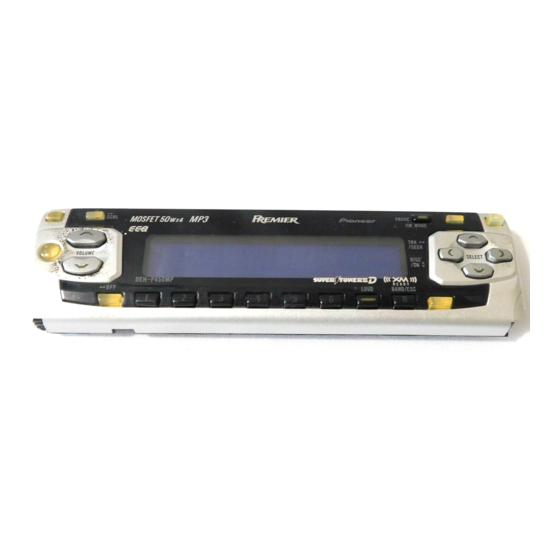
Exterior Views (DEH-P450MP, P4500MP)
Exploded view of exterior components for specific models.
Exterior Parts List (DEH-P450MP, P4500MP)
Detailed list of exterior parts for specific models.
Exterior Views (DEH-P3550MP)
Exploded view of exterior components for DEH-P3550MP.
Exterior Parts List (DEH-P3550MP)
Detailed list of exterior parts for DEH-P3550MP.
MODEL CONTRAST TABLE
DEH-P450MP/XM/UC vs DEH-P4500MP/XM/UC Differences
Lists variations between specified models.
CD MECHANISM MODULE
CD Mechanism Exploded View
Diagram showing the assembly of the CD mechanism.
CD Mechanism Parts List
Detailed list of parts for the CD mechanism.
SYSTEM DIAGRAMS
Overall Block Diagram
High-level overview of system components and connections.
Panel and Keyboard Unit Block Diagrams
Block diagrams for specific internal units.
Overall Connection Diagram
Diagram showing how major units connect.
KEYBOARD UNIT DIAGRAM
Keyboard Unit Pinout and Layout
Diagram showing the keyboard unit's structure and pins.
CD MECHANISM MODULE DIAGRAMS
CD Mechanism Block Diagram
Block diagram detailing CD mechanism internal functions.
WAVEFORM ANALYSIS
Signal Waveform Examples
Visual representations of signals during various operations.
PCB CONNECTION DIAGRAMS
Tuner Amp Unit PCB Layout
Connection diagram for the Tuner Amp Unit PCB.
Panel Unit PCB Layout
Detailed connection layout for the Panel Unit PCB.
Keyboard Unit PCB Layout
Detailed connection layout for the Keyboard Unit PCB.
CD Mechanism Module PCB Layout
Detailed connection layout for the CD Mechanism Module PCB.
ELECTRICAL PARTS LIST
Miscellaneous and IC Parts
List of miscellaneous components and integrated circuits.
LEDs, Diodes, Inductors, and Resistors
Listing of various electronic components.
ADJUSTMENT PROCEDURES
Jig Connection Diagram
Diagram showing the setup for adjustment jigs.
CD Adjustment Precautions and Test Mode
Cautions, notes, and test mode procedures for CD adjustment.
ADJUSTMENT FLOW CHART
Adjustment Sequence and Operations
Visual guide for adjustment sequence and operations.
GRATING CHECK AFTER PICKUP REPLACEMENT
Purpose, Symptoms, and Method
Objective, mal-adjustment signs, and required equipment.
Checking Procedure and Notes
Step-by-step guide and important observations for grating check.
ERROR MODE AND TROUBLESHOOTING
Error Messages and Display
Explanation of error codes and their display method.
Error Code List and Causes
Detailed table of error codes and their corresponding causes.
GENERAL INFORMATION
Diagnosis and Disassembly Steps
Initial diagnosis and basic disassembly procedures.
Mechanism Handling and Removal
Detailed steps for handling and removing unit mechanisms.
CONNECTOR FUNCTION DESCRIPTIONS
DEH-P450MP/XM/UC Connectors
Pinout descriptions for the DEH-P450MP/XM/UC model.
DEH-P3550MP/XM/ES Connectors
Pinout descriptions for the DEH-P3550MP/XM/ES model.
PARTS LIST
Integrated Circuits (ICs) and Pin Functions
List of ICs with detailed pin assignments and functions.
DISPLAY LAYOUTS
LCD Layout (CAW1759)
Diagram of the LCD segment connections for CAW1759.
LCD Layout (CAW1762)
Diagram of the LCD segment connections for CAW1762.
OPERATIONAL FLOW CHART
Power-On Operation Flowchart
Steps and conditions for powering on the unit.
CLEANING PROCEDURES
CD Pickup Lens Cleaning
Instructions and tools for cleaning CD pickup lenses.
OPERATIONS - HEAD UNIT
Basic Front Panel Controls
Descriptions of buttons like Clock, Display, Pause, Audio, Open.
Tuning, Source, and Volume Controls
Descriptions of buttons for tuning, source, volume, band, loudness, EQ.
OPERATIONS - REMOTE CONTROL
Remote Control Usage Overview
General operation and specific ATT function.
Remote Control Source Selection
TUNER and CD source selection buttons.
PLAYING A CD
CD Playback Steps and Controls
Inserting, playing, ejecting, and controlling CD playback.
CD Playback Notes and Error Handling
Important usage guidelines and error messages.
FRONT PANEL INSTALLATION
Attaching and Fixing the Front Panel
Steps for installing the front panel with holders and screws.
CONNECTION DIAGRAM
System Wiring Diagram
Overall wiring diagram for connecting components.
Need help?
Do you have a question about the DEH-P4500MP XM and is the answer not in the manual?
Questions and answers