Table of Contents
Advertisement
SERVICE MANUAL
Order No.Ref0905S003V0
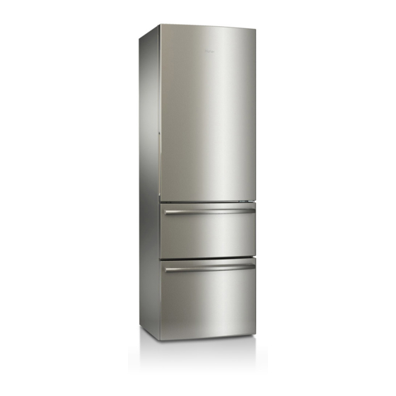
Refrigerator
MODEL:
AFL631*
CFE633*
WARNING
This service information is designed for experienced repair technicians only and is not designed for use by the general public. It
dose not contain warnings and cautions to advice non-technical individuals of potential dangers in attempting to service a product.
Product powered by electricity should by serviced or repaired only by experienced professional technicians. Any attempt to service
or repair the product or products dealt with in this service information by anyone else could result in serious injury or death.
◎2009(HAIER ELECTRICAL APPLIANCES COR. LTD)
All right reserved. Unauthorized copying and distribution is a violation of law。
Advertisement
Table of Contents

Summarization of Contents
Chapter 1 General Information
General Guidelines
Guidelines for safe and proper servicing procedures, including leakage current checks and ESD prevention.
Insurance Test Procedures
Steps and precautions for performing insurance tests to ensure electrical safety during servicing.
How to Read Service Manual
Explanation of icons and conventions used within the service manual for clarity.
Chapter 2 Product Feature
Product Specifications
Detailed technical specifications for AFL631 and CFE633 refrigerator models.
Main Functions and Features
Overview of key operational functions and distinguishing features of the refrigerator models.
External Views
Illustrations of three-door and two-door refrigerator structures, labeling internal compartments and features.
Product Dimensions
Detailed dimensions and measurements for both three-door and two-door refrigerator models.
Chapter 3 Disassembly
Freezer Drawer Handle Installation
Step-by-step guide for installing the handle onto the freezer drawer assembly.
Door Installation and Removal
Procedures for door removal/installation, covering hinges, decoration strips, and cables.
Freezer Drawer Removal
Steps to safely remove the freezer drawer from the refrigerator unit.
Cabinet Display Panel Removal
Procedure for removing the control display panel from the refrigerator cabinet.
Air-Duct Removal
Instructions for removing the air-duct components from both fridge and freezer sections.
Chapter 4 Control and display system
Control and Display Panel
Operation details for the control panel, including model-specific functions for CFE633* and AFL631*.
Error Codes and Sensor Locations
Description of error codes and graphical display of sensor positions for diagnostics.
Self-Test Model Procedure
Procedure for running self-tests to diagnose refrigeration and defrosting functions.
Chapter 5 Control principle of electronic component
Air Escaper Control
Principle of operation for the air door control based on temperature sensors.
Fan Control Principle
Explanation of how the freezer fan is controlled by the control panel and conditions.
Defrosting Control Principle
Detailed principle of how the automatic defrosting cycle is initiated and managed.
Chapter 6 System flow principle
Refrigeration Flow Chart
Diagram and description of the refrigerant cycle within the refrigerator system.
Refrigeration System Perspective
Visual representation of the refrigeration system components and their layout.
Air Flow Chart
Schematic of air circulation within the refrigerator's air-duct system.
Chapter 7 Circuit diagram
Main Control PCB Diagram
Schematic diagram of the main control printed circuit board and its connections.
Main Control PCB Connections
Detailed pinout and connection descriptions for the main control PCB connectors.
Chapter 8 Trouble shooting
Common Problems & Solutions
Troubleshooting common issues like freezing, alarms, and operational failures.
Other Problems Examination
Solutions for less common problems related to moisture, operation, odors, and sounds.
Troubleshooting Flow Chart
Diagnostic flowchart for compressor starting issues and related component checks.


Need help?
Do you have a question about the CFE633 series and is the answer not in the manual?
Questions and answers