Table of Contents
Advertisement
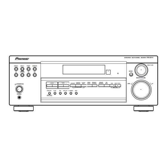
AUDIO/VIDEO MULTI-CHANNEL RECEIVER
VSX-D514-K
VSX-D514-S
VSX-D414-K
VSX-D414-S
THIS MANUAL IS APPLICABLE TO THE FOLLOWING MODEL(S) AND TYPE(S).
Model
Type
VSX-D514-K
KUCXJI
VSX-D514-S
KUCXJI
VSX-D414-K
KUCXJI
VSX-D414-S
KUCXJI
For details, refer to "Important symbols for good services".
PIONEER CORPORATION
PIONEER ELECTRONICS (USA) INC. P.O. Box 1760, Long Beach, CA 90801-1760, U.S.A.
PIONEER EUROPE NV Haven 1087, Keetberglaan 1, 9120 Melsele, Belgium
PIONEER ELECTRONICS ASIACENTRE PTE. LTD. 253 Alexandra Road, #04-01, Singapore 159936
PIONEER CORPORATION 2004
DVD/LD
DVD 5.1
TV/SAT
CD-R/
CD
TAPE/MD
FM
STANDBY / ON
PHONES
Power Requirement
AC120V
AC120V
AC120V
AC120V
4-1, Meguro 1-chome, Meguro-ku, Tokyo 153-8654, Japan
AUDIO/VIDEO MULTI-CHANNEL RECEIVER
DVR/VCR
ENTER
AM
MASTER VOLUME
ADVANCED
STEREO/
SIGNAL
MIDNIGHT/
SPEAKER
VSB
STATION
TUNING
STANDARD
TONE
QUICK SETUP
SURROUND
DIRECT
SELECT
LOUDNESS
IMPEDANCE
MODE
DO WN
LISTENING MODE
MULTI JOG
TUNER EDIT
CLASS
MPX
INPUT ATT
FL DIMMER
MUTE
MULTI JOG
VSX-D514-K
VSX-D514
MULTI JOG
UP
ORDER NO.
RRV2901
Remarks
ZZK FEB. 2004 printed in Japan
Advertisement
Table of Contents

Related Manuals for Pioneer VSX-D414-S


Summarization of Contents
SAFETY INFORMATION
1. SAFETY PRECAUTIONS
Checks for customer and service technician protection.
LEAKAGE CURRENT CHECK
Procedure to measure leakage current to earth ground.
2. PRODUCT SAFETY NOTICE
Highlights special safety characteristics of replacement parts.
1. SPECIFICATIONS
Amplifier Section
Details power output, distortion, sensitivity, and tone control specifications.
Video Section
Provides specifications for video inputs, outputs, frequency response, and S/N ratio.
FM Tuner Section
Specifies FM tuner range, sensitivity, selectivity, separation, and frequency response.
AM Tuner Section
Specifies AM tuner range, sensitivity, and signal-to-noise ratio.
Miscellaneous
Lists power requirements, consumption, dimensions, weight, and furnished parts.
Accessories
Illustrates included accessories like remote control, antennas, and batteries.
2. EXPLODED VIEWS AND PARTS LIST
2.1 PACKING
Shows the packing configuration and components, including case, pads, and sheet.
PACKING parts List
Lists parts for packing, including antennas, batteries, and remote control.
CONTRAST TABLE
Compares parts construction for different models: VSX-D514-K/S and VSX-D414-K/S.
2.2 EXTERIOR SECTION
Exploded view of exterior parts, showing chassis, panels, and connectors.
EXTERIOR SECTION parts List
Lists parts for the exterior section, including assemblies, fuses, and screws.
CONTRAST TABLE
Compares exterior parts for different models: VSX-D514-K/S and VSX-D414-K/S.
2.3 FRONT PANEL SECTION
Exploded view of front panel components, including display, knobs, and buttons.
FRONT PANEL SECTION parts List
Lists parts for the front panel section, including displays, encoders, knobs, and buttons.
CONTRAST TABLE
Compares front panel parts for different models: VSX-D514-K/S and VSX-D414-K/S.
3. BLOCK DIAGRAM AND SCHEMATIC DIAGRAM
3.1 BLOCK DIAGRAM
Shows overall signal flow and major functional blocks of the receiver.
3.2 OVERALL WIRING CONNECTION DIAGRAM
Illustrates wiring connections between internal assemblies and external connectors.
Overall Wiring Connections to Assemblies
Details wiring from main assemblies to other units like display, encoder, DSP, and tuner.
Wiring Legend and Connections
Explains connector types and shows wiring to power supply, amplifier, and component boards.
3.3 MAIN ASSY (1/3) Schematic
Schematic for Main Assembly, detailing input circuits, function selection, and volume control.
3.3 MAIN ASSY (1/3) Schematic (Cont.)
Schematic for Main Assembly, covering low-pass filters and audio processing circuits.
3.4 MAIN ASSY (2/3) Schematic
Schematic for Main Assembly, focusing on 6-channel E-volume control and DSP interface.
3.5 MAIN ASSY (3/3) Schematic
Schematic for Main Assembly, detailing pre-amplifier circuits and output controls.
3.5 MAIN ASSY (3/3) Schematic (Cont.)
Schematic for Main Assembly, covering tuner and video interface connections.
3.6 DSP ASSY (1/2) Schematic
Schematic for DSP Assembly, covering input/output signals and microcontroller connections.
3.6 DSP ASSY (1/2) Schematic (Cont.)
Schematic for DSP Assembly, detailing ICs, filters, and digital interfaces.
3.6 DSP ASSY (1/2) Schematic (Cont.)
Schematic for DSP Assembly, detailing audio codec and control signals.
3.7 DSP ASSY (2/2) Schematic
Schematic for DSP Assembly, covering level shifters and JTAG interface.
3.7 DSP ASSY (2/2) Schematic (Cont.)
Schematic for DSP Assembly, detailing audio processing and controller interfaces.
3.8 AMP & PRIMARY (1/2), TRANS2, TRANS3 ASSYS Schematics
Schematics for Amplifier & Primary, Trans2, and Trans3 assemblies, showing power output stages.
3.8 AMP & PRIMARY (2/2), REGULATOR, AMP INPUT, TRANS1 ASSYS Schematics
Schematics for Amplifier & Primary, Regulator, Amp Input, and Trans1 assemblies, including power supply.
3.9 AMP & PRIMARY (2/2), REGULATOR, AMP INPUT, TRANS1 ASSYS Schematics
Schematics for Regulator, Amp Input, and Trans1 assemblies, detailing power supply regulation and signal routing.
3.9 AMP & PRIMARY (2/2), REGULATOR, AMP INPUT, TRANS1 ASSYS Schematics (Cont.)
Schematics for Amp Input and Primary assemblies, showing power relay and fuse connections.
3.10 VIDEO, 5.1CH, B TO B, S. VIDEO ASSYS Schematics
Schematics for Video, 5.1CH, B to B, and S. Video assemblies, including function selectors.
3.10 VIDEO, 5.1CH, B TO B, S. VIDEO ASSYS Schematics (Cont.)
Schematics for B to B and S. Video assemblies, detailing control signals and video processing.
3.11 FRONT DISPLAY, R. ENCODER, P. SW&FUNC KEY, F. KEY ASSYS Schematics
Schematics for Front Display, R. Encoder, P. SW & Func Key, and F. Key assemblies.
3.11 FRONT DISPLAY, R. ENCODER, P. SW & FUNC KEY, H. P., F. KEY ASSYS Schematics (Cont.)
Schematics for Front Key and Power SW & Function Key assemblies, including button assignments.
3.12 H.P. and COMPONENT ASSYS Schematics
Schematics for Headphone (H.P.) and Component assemblies, detailing audio input/output and control signals.
4. PCB CONNECTION DIAGRAM
PCB Layout Diagrams
Diagrams illustrating PCB layouts, component symbols, and connections for transistors and regulators.
4.1 TRANS2, TRANS3, TRANS1 ASSYS PCB Layouts
PCB layout diagrams for Trans2, Trans3, and Trans1 assemblies, showing component placement.
4.2 REGULATOR ASSY PCB Layout
PCB layout diagram for Regulator Assembly, indicating component positions and connector locations.
4.3 MAIN ASSY PCB Layout
PCB layout diagram for Main Assembly, showing component placement and connector assignments.
4.3 MAIN ASSY PCB Layout (Cont.)
PCB layout diagram for Main Assembly, detailing signal routing and component placement.
4.4 DSP ASSY PCB Layout
PCB layout diagram for DSP Assembly, showing component placement and connector interfaces.
4.4 DSP ASSY PCB Layout (Cont.)
PCB layout diagram for DSP Assembly, detailing component placement and signal routing.
4.5 AMP & PRIMARY, AMP INPUT ASSYS PCB Layouts
PCB layout diagrams for Amp & Primary and Amp Input assemblies.
4.5 AMP & PRIMARY, AMP INPUT ASSYS PCB Layouts (Cont.)
PCB layout diagrams for Amp & Primary and Amp Input assemblies, showing component placement.
4.6 F. DISPLAY, R. ENCODER, P. SW & FUNC KEY, H. P., F. KEY ASSYS PCB Layouts
PCB layouts for Front Display, R. Encoder, P. SW & Func Key, H.P., and F. Key assemblies.
4.6 F. DISPLAY, R. ENCODER, P. SW & FUNC KEY, H. P., F. KEY ASSYS PCB Layouts (Cont.)
PCB layouts for Front Key and Power SW & Function Key assemblies, showing component placement.
4.6 F. DISPLAY, R. ENCODER, P. SW & FUNC KEY, H. P., F. KEY ASSYS PCB Layouts (Cont.)
PCB layouts for H.P. Assembly and Power SW & Function Key Assembly.
4.6 F. DISPLAY, R. ENCODER, P. SW & FUNC KEY, H. P., F. KEY ASSYS PCB Layouts (Cont.)
PCB layouts for Front Display and Front Key assemblies, detailing component placement.
4.6 F. DISPLAY, R. ENCODER, P. SW & FUNC KEY, H. P., F. KEY ASSYS PCB Layouts (Cont.)
PCB layouts for R. Encoder and Front Key assemblies, showing component placement.
4.6 F. DISPLAY, R. ENCODER, P. SW & FUNC KEY, H. P., F. KEY ASSYS PCB Layouts (Cont.)
PCB layouts for Front Display, H.P. Assembly, and P. SW & Function Key Assembly.
4.6 F. DISPLAY, R. ENCODER, P. SW & FUNC KEY, H. P., F. KEY ASSYS PCB Layouts (Cont.)
PCB layouts for Front Display, P. SW & Func Key, and H.P. Assembly.
4.6 F. DISPLAY, R. ENCODER, P. SW & FUNC KEY, H. P., F. KEY ASSYS PCB Layouts (Cont.)
PCB layouts for Front Display, Front Key, and R. Encoder assemblies.
4.6 F. DISPLAY, R. ENCODER, P. SW & FUNC KEY, H. P., F. KEY ASSYS PCB Layouts (Cont.)
PCB layouts for Front Display, Front Key, and R. Encoder assemblies.
4.6 F. DISPLAY, R. ENCODER, P. SW & FUNC KEY, H. P., F. KEY ASSYS PCB Layouts (Cont.)
PCB layouts for Front Display, H.P. Assembly, and P. SW & Function Key Assembly.
4.7 B TO B, VIDEO, 5.1CH ASSYS PCB Layouts
PCB layouts for B to B, Video, and 5.1CH assemblies, showing component placement.
4.7 B TO B, VIDEO, 5.1CH ASSYS PCB Layouts (Cont.)
PCB layouts for 5.1CH, Video assemblies, detailing component placement and connections.
4.7 B TO B, VIDEO, 5.1CH ASSYS PCB Layouts (Cont.)
PCB layouts for Video assemblies, detailing component placement and connections.
4.7 B TO B, VIDEO, 5.1CH ASSYS PCB Layouts (Cont.)
PCB layouts for 5.1CH and Video assemblies, showing component placement and connections.
4.8 S.VIDEO and COMPONENT ASSYS PCB Layouts
PCB layouts for S. Video and Component assemblies, showing component placement and connections.
4.8 S.VIDEO and COMPONENT ASSYS PCB Layouts (Cont.)
PCB layouts for Component and S. Video assemblies, detailing component placement and connections.
5. PCB PARTS LIST
Specific PCB Assembly Parts Lists
Lists all PCB assemblies and their part numbers, including main, DSP, amplifier, and tuner boards.
Specific PCB Assembly Parts Lists (Cont.)
Detailed parts lists for various assemblies like Amp & Primary, Video, Front Display, R. Encoder, etc.
PCB Parts Lists - Semiconductors, Coils, Capacitors, Resistors, Others
Categorized parts lists for DSP Assy, Main Assy, and other components like semiconductors and capacitors.
PCB Parts Lists - Semiconductors, Capacitors, Resistors, Others
Detailed parts lists for Camp & Primary Assy, Trans2, Trans3, Regulator assemblies, and associated components.
PCB Parts Lists - Various Components and Assemblies
Parts lists for Amp Input, Trans1, Video, 5.1CH, and Front Display assemblies, including semiconductors and capacitors.
PCB Parts Lists - Encoder, Switches, H.P., Component Assemblies
Parts lists for R. Encoder, P. SW & Func, Front Key, H.P., and Component assemblies.
6. ADJUSTMENT
Adjustment Information
Indicates that no adjustment information is available in this section.
7. GENERAL INFORMATION
7.1 DIAGNOSIS
Covers diagnostic procedures, including timing charts and failure analysis.
POWER ON AND OFF INITIAL TIMING CHART
Charts detailing the sequence and timing of signals during power on and off operations.
7.1.2 IC DATA TRANSMISSION TIMING CHART
Timing charts illustrating data transmission between ICs during function changes and other operations.
7.1.3 DETECTION CIRCUIT
Diagrams of DC detection, overload detection, and PCB board protection circuits for amplifier safety.
7.1.4 AMPLIFIER SYSTEM PROTECTION OPERATION SPECIFICATION
Details amplifier protection operation for DC abnormality, overload, and board errors.
Amplifier Protection - Board Detection
Explains the operation of the board detection circuit and its response to errors.
7.1.5 AMPLIFIER FAILURE DIAGNOSIS FLOW CHART
Flow chart to diagnose amplifier failures, including checks for fan motor, fuses, voltages, and output DC.
7.1.6 DISASSEMBLY
Step-by-step instructions and diagrams for disassembling the unit, including heat sink precautions.
Disassembly - Internal View
Illustrates the location of major assemblies like Main, DSP, Regulator, and Tuner units after partial disassembly.
7.2 PARTS
7.2.1 IC List and Pin Arrangement
Lists integrated circuits (ICs) used in the unit, including their part numbers and pin arrangements.
IC Pin Function Details
Detailed description of the pin functions for the PD5963B MCU, including ports and their purposes.
IC Pin Function Details (Cont.)
Detailed description of pin functions for the PD5963B MCU, covering gain selection, mute, and relay controls.
PE5420A IC Pin Arrangement
Pin arrangement and function details for the PE5420A IC used in the Front Assy.
PE5420A IC Pin Function Details
Detailed pin functions for PE5420A IC, covering LED outputs, display control, and input/output signals.
PE5420A IC Pin Function Details (Cont.)
Further details on PE5420A IC pin functions, including display control and LED output assignments.
BD3841FS IC Block Diagram
Block diagram of the BD3841FS IC, showing its logic structure and function switch inputs/outputs.
BD3841FS Terminal Description
Description of each terminal on the BD3841FS IC, detailing input/output functions and descriptions.
BD3813KS IC Block Diagram
Block diagram of the BD3813KS IC, illustrating audio processing functions and internal routing.
BD3813KS Terminal Description
Description of each terminal on the BD3813KS IC, detailing input/output functions and descriptions.
7.2.2 DISPLAY - FL DISPLAY Pin Assignment
Pin assignment for the FL Display unit (XAV3022), showing signal connections to the display elements.
FL DISPLAY Grid and Segment Designation
Grid and segment designation for the FL Display, illustrating how characters and symbols are formed.
FL DISPLAY Pin Connection Details
Details the pin connections for the FL Display, mapping pin numbers to grid and segment assignments.
FL DISPLAY Anode Connection Mapping
Maps anode connections to display grid points (10G to 1G) and segments for character formation.
8. PANEL FACILITIES
Front Panel Controls and Functions
Details the function of each front panel control, including power, input select, tuning, and volume.
Front Panel Display Indicators
Explains the meaning of various indicators on the FL display, such as signal select, tuner status, and volume level.
Remote Control Operation
Remote Control Functions - Detailed
Explains the functions of the remote control buttons, including receiver, DVD, and tuner controls.
Remote Control Functions - Detailed (Cont.)
Details functions of Mute, Sleep, FL Dimmer, Input Att, Input Select, Tuner controls, and DVD controls.
Need help?
Do you have a question about the VSX-D414-S and is the answer not in the manual?
Questions and answers