Table of Contents
Advertisement
Quick Links
SLV-D910AZ/D910B/D910E/D910N/D910R/
SERVICE MANUAL
RMT-V503B
System
Laser
Semiconductor laser
Signal format system
PAL/(NTSC)
SLV-D910B/D950B:
SECAM
SLV-D910B/D910N/D910R/D950B:
MESECAM
Channel coverage
SLV-D910B/D910E/D950B/D950E:
PAL (B/G):
VHF E2 to E12
VHF Italian channel A to H
UHF E21 to E69
CATV S01 to S05, S1 to S20
HYPER S21 to S41
SLV-D950GI:
PAL (I):
VHF IA to IJ, SA10 to SA13
UHF B21 to B69
CATV S01 to S05, S1 to S20
HYPER S21 to S41
PAL
SLV-D950B
SPECIFICATIONS
SLV-D910B/D950B:
SECAM (L):
VHF F2 to F10
UHF F21 to F69
CATV B to Q
HYPER S21 to S41
SLV-D910N/D910R:
PAL (B/G, D/K):
VHF E2 to E12, R1–R12
UHF E21 to E69, R21–R69
CATV S01 to S05, S1 to S41
SLV-D910AZ:
B/G: VHF E2 to E12/UHF E21 to E69/
CATV S01 to S05, S1 to S41
B/B: VHF R1 to R12/UHF R21 to R69
RF output signal
SLV-D910E/D910N/D910R/D950E/D950GI:
UHF channels 21 to 69
SLV-D910AZ:
UHF channels 21 to 69 (B/G)
UHF channels 28 to 69 (B/B)
D950B/D950E/D950GI
RMT-V503A/V503B
SLV-D910B/D910E/D910N/D950B/D950E
Russian Model
Refer to the SERVICE MANUAL of VHS MECHANI-
CAL ADJUSTMENT MANUAL VII for MECHANICAL
ADJUSTMENTS. (9-921-790-11)
Aerial out
75-ohm asymmetrical aerial socket
Tape speed
SP: PAL
NTSC
SLV-D910B/D950B:
SECAM
MESECAM
SLV-D910N/D910R:
MESECAM
— Continued on next page —
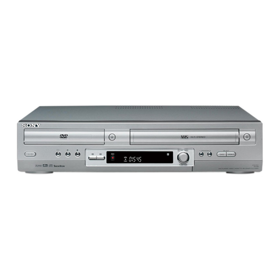
VIDEO CASSETTE RECORDER
AEP Model
UK Model
SLV-D950GI
E Model
SLV-D910AZ
SLV-D910R
TS-10 MECHANISM
23.39 mm/s
(recording/playback)
33.35 mm/s
(playback only)
23.39 mm/s
(recording/playback)
23.39 mm/s
(playback only)
23.39 mm/s
(recording/playback)
DVD PLAYER/
Advertisement
Table of Contents

Summarization of Contents
SPECIFICATIONS
System
Details on signal format, channel coverage, and tape speed specifications.
Timer Section
Information regarding clock settings, timer indication, and program scheduling.
General Specifications
Covers power requirements, unit dimensions, mass, and supplied accessories.
PRECAUTIONS
Safety Precautions
Essential safety checks and warnings for servicing the unit.
Servicing Precautions
Guidelines for servicing procedures, component replacement, and insulation checks.
ESD Precautions
Techniques to prevent damage to components from electrostatic discharge.
Handling the Optical Pick-up
Procedures for safely handling and working with the optical pick-up unit.
Pick-up Disassembly and Reassembly
Step-by-step instructions for disassembling and reassembling the pick-up unit.
GENERAL
Getting Started
Initial steps for unpacking, model identification, and basic setup.
Remote Commander Setup
Instructions for inserting batteries and operating the remote commander.
Connecting the DVD-VCR
Guides for connecting the DVD-VCR to TV and other external devices.
DVD-VCR Setup and Operations
Auto Set Up Function
Automatic setup process for channels, clock, and TV system.
Selecting a Language
Instructions on how to choose the on-screen display language.
Setting the Clock
Procedure for setting the unit's internal clock and date.
Presetting Channels
Manual tuning process for storing TV channels.
Basic Operations
Playing Discs
How to play DVD and CD discs, including navigation and playback modes.
Playing a Tape
Instructions for VCR tape playback, including special modes.
Recording Operations
Covers timer, ShowView, and Dial Timer recording procedures.
DISASSEMBLY AND REASSEMBLY
Cabinet and PCB Removal
Procedures for removing the unit's cabinet and main PCBs.
Chassis Removal
Steps for removing the main chassis and its associated components.
VCR Deck Parts Locations
Diagrams illustrating the location of various VCR deck components.
DVD Deck Parts Locations
Diagrams illustrating the location of various DVD deck components.
PCB DIAGRAMS
VCR Main PCB Diagrams
Component and conductor side layouts for the VCR main board.
DVD Main PCB Diagrams
Component and conductor side layouts for the DVD main board.
SMPS PCB Diagrams
Component and conductor side layouts for the SMPS board.
SCHEMATIC DIAGRAMS
VCR Main PCB Schematics
Detailed circuit schematics for the VCR main board.
DVD Main PCB Schematics
Detailed circuit schematics for the DVD main board.
ALIGNMENT AND ADJUSTMENTS
VCR Adjustment
Procedures for VCR tracking, head switching, and NVRAM settings.
DVD Adjustment
Steps for adjusting DVD playback parameters like skew.
VCR Mechanical Adjustment
Mechanical adjustments for the tape transport system.
TROUBLESHOOTING
VCR Troubleshooting
Flowcharts to diagnose and resolve VCR operational issues.
DVD Troubleshooting
Flowcharts to diagnose and resolve DVD operational issues.
REPAIR PARTS LIST
Exploded Views
Illustrated diagrams showing parts for assembly and disassembly.
Electrical Parts List
List of electronic components with part numbers and descriptions.


Need help?
Do you have a question about the SLV-D910E and is the answer not in the manual?
Questions and answers