Table of Contents
Advertisement
SPLIT-TYPE, HEAT PUMP AIR CONDITIONERS
SPLIT-TYPE, AIR CONDITIONERS
SERVICE MANUAL
Indoor unit
[Model names]
[Service Ref.]
PKA-RP60KAL.TH
PKA-RP60KAL
PKA-RP71KAL.TH
PKA-RP71KAL
PKA-RP100KAL.TH
PKA-RP100KAL
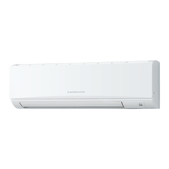
INDOOR UNIT
WIRELESS REMOTE
CONTROLLER
ON/OFF
TEMP
CONTENTS
1. REFERENCE MANUAL ................................... 2
2. SAFETY PRECAUTION ................................... 3
3. PART NAMES AND FUNCTIONS ................... 4
4. SPECIFICATIONS ............................................ 6
5. NOISE CRITERION CURVES .......................... 7
6. OUTLINES AND DIMENSIONS ....................... 8
7. WIRING DIAGRAM .......................................... 9
8. REFRIGERANT SYSTEM DIAGRAM ............ 10
9. TROUBLESHOOTING .................................... 11
10. SPECIAL FUNCTION ..................................... 26
11. DISASSEMBLY PROCEDURE ....................... 29
PARTS CATALOG (OCB452)
February 2009
No. OCH452
NOTE:
• This manual describes
only service data of the
indoor units.
• RoHS compliant products
have <G> mark on the
spec name plate.
Advertisement
Table of Contents
Troubleshooting

Summarization of Contents
1 REFERENCE MANUAL
OUTDOOR UNIT'S SERVICE MANUAL
Lists service manual numbers for various outdoor units.
2 SAFETY PRECAUTION
2-1. ALWAYS OBSERVE FOR SAFETY
General safety rules before accessing terminals.
2-2. CAUTIONS RELATED TO NEW REFRIGERANT
Guidelines for safe handling of R410A refrigerant and associated equipment.
3 PART NAMES AND FUNCTIONS
Indoor Unit Components
Identifies and describes the parts of the indoor unit.
Wireless Remote Controller
Explains the functions and display indicators of the wireless remote controller.
5 NOISE CRITERION CURVES
5-1. SOUND LEVELS
Presents sound level data measured in anechoic rooms.
5-2. NOISE CRITERION CURVES
Displays noise criterion curves for different frequency bands.
7 WIRING DIAGRAM
Diagram Legend and Notes
Explains symbols and provides notes for the wiring diagram.
9 TROUBLESHOOTING
9-1. TROUBLESHOOTING SUMMARY
Overview of self-diagnosis error codes and service actions.
9-2. MALFUNCTION DIAGNOSIS METHOD
Procedure to diagnose malfunctions using the remote controller.
Error Code Classification and Symptoms
Classifies errors detected by indoor/outdoor units and lists symptoms.
9-3. SELF-DIAGNOSIS ACTION TABLE
Details errors, causes, and countermeasures for self-diagnosis codes.
9-4. TROUBLESHOOTING BY PHENOMENA
Troubleshooting based on observed unit phenomena and LED indicators.
9-5. EMERGENCY OPERATION
Emergency Operation Procedures
Guides for operating the unit in emergency mode when controls fail.
9-6. HOW TO CHECK THE PARTS
9-6-1. Thermistor Checks
Instructions and characteristic graphs for checking thermistors.
9-6-2. DC Fan Motor Checks
Procedure for checking the DC fan motor and its associated circuit.
10 SPECIAL FUNCTION
10-1. ROTATION AND BACK-UP FUNCTIONS
Details on rotation, back-up, and 2nd stage cut-in functions.
Setting Functions via Wired Remote Controller
Guide to setting special functions using the wired remote controller.
11 DISASSEMBLY PROCEDURE
1. Removing the Panel
Steps for safely removing the front panel of the indoor unit.
2. Removing Electrical Box
Procedure for removing the electrical box, nozzle assembly, and vane motor.
3. Removing Fan Motor and Fan
Steps to remove the indoor fan motor, line flow fan, and thermistors.
4. Removing Heat Exchanger and Thermistors
Procedure for removing the heat exchanger and room temperature thermistor.


Need help?
Do you have a question about the Mr.Slim PKA-RP100KAL and is the answer not in the manual?
Questions and answers