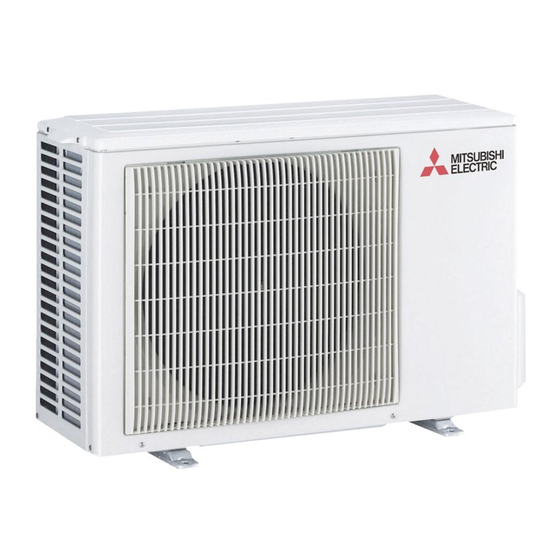
Table of Contents
Advertisement
SPLIT-TYPE AIR CONDITIONERS
SERVICE MANUAL
Models
MUZ-FH25VE
MUZ-FH35VE
MUZ-FH25VE
MUZ-FH35VE
NOTE:
RoHS compliant products have <G> mark on the spec name plate.
-
E1
-
E1
-
E1
CONTENTS
1. TECHNICAL CHANGES ··································· 3
2. PART NAMES AND FUNCTIONS ····················· 3
3. SPECIFICATION ················································ 4
4. NOISE CRITERIA CURVES ······························ 7
5. OUTLINES AND DIMENSIONS ························ 8
6. WIRING DIAGRAM ············································ 9
7. REFRIGERANT SYSTEM DIAGRAM ··············11
8. PERFORMANCE CURVES ····························· 13
9. ACTUATOR CONTROL ··································· 24
10. SERVICE FUNCTIONS ···································· 25
11. TROUBLESHOOTING ····································· 26
12. DISASSEMBLY INSTRUCTIONS ···················· 47
PARTS CATALOG (OBB624)
• MUZ-FH50VE-
has been added.
E1
Please void OBH624.
No. OBH624
HFC
REVISED EDITION-A
utilized
R410A
Indoor unit service manual
MSZ-FH•VE Series (OBH623)
Advertisement
Table of Contents

Summarization of Contents
Technical Changes Overview
New Model Introduction
Details about new models added to the service manual.
Part Names and Functions
Outdoor Unit Components and Accessories
Identification and descriptions of outdoor unit parts and accessories.
Technical Specifications
Electrical and Performance Specifications
Detailed electrical data, dimensions, air flow, sound level, and refrigerant capacity.
Noise Criteria Curves
Noise Performance Evaluation
Graphs showing noise criteria curves for different models under various conditions.
Outlines and Dimensions
Unit Dimensions and Installation Space
Diagrams showing overall dimensions and required installation clearances for outdoor units.
Wiring Diagram
Electrical Schematics for Outdoor Units
Wiring diagrams and component symbols for the outdoor units.
Refrigerant System Diagram
Refrigerant Circuit Overview
Diagrams illustrating the refrigerant flow and key components of the system.
Performance Curves
Operating Condition Parameters
Details on guaranteed voltage, air flow, and main readings for performance analysis.
Capacity and Input Curves
Charts showing cooling capacity and input based on indoor and outdoor conditions.
Operational Frequency Corrections
Graphs illustrating capacity and input corrections based on compressor operational frequency.
Outdoor Unit Current and Pressure Data
Data on outdoor unit current and low pressure under various cooling and heating conditions.
Actuator Control Logic
Fan and Valve Control Logic
Explains the control logic for the outdoor fan motor and the reversing valve coil.
Sensor-Actuator Relationships
Table detailing how sensors relate to compressor, LEV, fan motor, and other actuators.
Service Functions
Defrost Finish Temperature Adjustment
Procedure to change the defrost finish temperature setting via a jumper wire.
Pre-Heat Control Activation
Instructions for activating pre-heat control to prevent compressor issues during low load operation.
Troubleshooting and Fault Diagnosis
Troubleshooting Precautions
Essential safety precautions and general guidelines before starting troubleshooting.
Failure Mode Recall Function
Procedures for recalling and interpreting failure modes using the remote controller and unit indicators.
Outdoor Unit Failure Diagnosis
Flow chart and tables for diagnosing specific outdoor unit abnormalities based on LED indications and fault codes.
Troubleshooting Check Table
Reference table listing symptoms, LED indications, conditions, and remedies for common faults.
Main Part Trouble Criteria
Criteria and methods for checking the normal operation of main electrical and mechanical parts.
Detailed Troubleshooting Flows and Component Checks
Step-by-step guides for diagnosing specific components like compressor, thermistors, and power supply.
Electromagnetic Noise Interference
Guidance on identifying and mitigating electromagnetic noise affecting TV sets or radios.
Disassembly and Component Removal
Cabinet and Panel Removal
Step-by-step instructions for removing external panels and covers of the outdoor unit.
Inverter and Relay Board Removal
Procedures for safely removing the inverter and relay P.C. boards.
Specific Component Removal
Instructions for removing R.V. coil, thermistors, fan motor, compressor, and 4-way valve.


Need help?
Do you have a question about the MUZ-FH35VE - E1 and is the answer not in the manual?
Questions and answers