Table of Contents
Advertisement
Quick Links
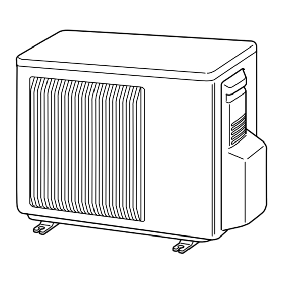
OUTDOOR UNIT
SERVICE MANUAL
Wireless type
Models
MUZ-FD09NA
MUZ-FD09NA-
MUZ-FD12NA
MUZ-FD12NA-
NOTE:
RoHS compliant products have <G> mark on the spec name plate.
U1
U1
CONTENTS
1. TECHNICAL CHANGES ··································· 3
2. PART NAMES AND FUNCTIONS ····················· 3
3. SPECIFICATION ················································ 4
4. OUTLINES AND DIMENSIONS ························ 6
5. WIRING DIAGRAM ············································ 7
6. REFRIGERANT SYSTEM DIAGRAM ··············· 8
7. DATA ·································································· 9
8. ACTUATOR CONTROL ··································· 15
9. SERVICE FUNCTIONS ··································· 16
10. TROUBLESHOOTING ····································· 16
11. DISASSEMBLY INSTRUCTIONS ···················· 32
PARTS CATALOG (OBB498)
No. OBH498
HFC
utilized
R410A
Indoor unit service manual
MSZ-FD•NA Series (OBH497)
TM
Advertisement
Table of Contents
Troubleshooting

Related Manuals for Mitsubishi Electric Mr.Slim MUZ-FD09NA-U1


Summary of Contents for Mitsubishi Electric Mr.Slim MUZ-FD09NA-U1
-
Page 1: Table Of Contents
OUTDOOR UNIT No. OBH498 SERVICE MANUAL utilized R410A Wireless type Models MUZ-FD09NA MUZ-FD09NA- MUZ-FD12NA MUZ-FD12NA- Indoor unit service manual MSZ-FD•NA Series (OBH497) CONTENTS 1. TECHNICAL CHANGES ··································· 3 2. PART NAMES AND FUNCTIONS ····················· 3 3. SPECIFICATION ················································ 4 4. OUTLINES AND DIMENSIONS ························ 6 5. -
Page 3: Technical Changes
TECHNICAL CHANGES MUZ-FD09NA MUZ-FD12NA MUZ-FD09NA - MUZ-FD12NA - 1. New model PART NAMES AND FUNCTIONS MUZ-FD09NA MUZ-FD12NA Air inlet Piping Drain hose Air outlet Drain outlet... -
Page 4: Specification
SPECIFICATION Outdoor unit model MUZ-FD09NA MUZ-FD12NA Btu/h 9,000 (2,800~9,000) 12,000 (2,800~12,000) Cooling 1 Capacity Rated (Minimum~Maximum) Heating 47 1 Btu/h 10,900 (3,000~18,000) 13,600 (3,000~21,000) Capacity Rated Btu/h 12,500 13,600 Heating 17 2 Cooling 1 650 (160~650) 960 (160~960) Power consumption Rated (Minimum~Maximum) 750 (150~2,400) 980 (150~2,400) - Page 5 Test condition 3, 4 Indoor air condition Outdoor air condition Mode Test Dry bulb (°F) Wet bulb (°F) Dry bulb (°F) Wet bulb (°F) "A" Cooling Steady State (75) at rated compressor Speed "B-2" Cooling Steady State (65) at rated compressor Speed SEER "B-1"...
-
Page 6: Outlines And Dimensions
OUTLINES AND DIMENSIONS MUZ-FD09NA Unit: inch MUZ-FD12NA REQUIRED SPACE Basically open 4 inch or more without any obstruction in front 15-3/4 Drain hole 1-5/8 and on both sides of the unit. Air in Air in 1-9/16 Air out 2- 3/8 13/16 Oval hole 29/32 11-1/4... -
Page 7: Wiring Diagram
WIRING DIAGRAM MUZ-FD09NA MUZ-FD12NA... -
Page 8: Refrigerant System Diagram
REFRIGERANT SYSTEM DIAGRAM MUZ-FD09NA Unit:inch MUZ-FD12NA 4-way valve Refrigerant pipe ø3/8 (with heat insulator) Muffler Outdoor heat exchanger temperature Stop valve thermistor RT68 (with service port) Outdoor Muffler Discharge heat Flared connection exchanger temperature Service thermistor port RT62 Ambient Compressor Service temperature port... -
Page 9: Data
DATA MUZ-FD09NA MUZ-FD12NA 7-1. PERFORMANCE DATA 1) COOLING CAPACITY Indoor air Outdoor intake air DB temperature (˚F) Model (˚F) SHC TPC SHC TPC SHC TPC SHC TPC SHC TPC 11.0 0.58 10.3 0.63 0.68 0.72 0.75 10.4 0.55 0.60 0.65 0.69 0.72 MUZ-FD09NA... - Page 10 7-2. PERFORMANCE CURVE Cooling MUZ-FD12NA MUZ-FD09NA SHF at rating condition = 0.76 SHF at rating condition = 0.73 Airflow = 307 CFM Airflow = 350 CFM Outdoor intake air DB temperature (°F) Outdoor intake air DB temperature (°F) Heating MUZ-FD09NA MUZ-FD12NA Airflow = 381 CFM...
- Page 11 7-3. CONDENSING PRESSURE Cooling Data is based on the condition of indoor humidity 50 %. Air flow should be set to High speed. MUZ-FD09NA (PSIG) (PSIG) 68 70 105(°F) 68 70 105(°F) Outdoor ambient temperature Outdoor ambient temperature MUZ-FD12NA (PSIG) (PSIG) 68 70 105(°F)
- Page 12 Heating Data is based on the condition of outdoor humidity 75 %. Air flow should be set to High speed. Data is for heating operation without any frost. MUZ-FD09NA (PSIG) (PSIG) 58Hz 58Hz 20 25 30 35 40 45 50 55 60 65 70 65 70(°F) (°F) Outdoor ambient temperature...
- Page 13 7-4. STANDARD OPERATION DATA Model MSZ-FD09NA MSZ-FD12NA Item Unit Cooling Heating Cooling Heating Capacity Btu/h 9,000 10,900 12,000 13,600 — 0.76 — 0.73 — Input 0.650 0.750 0.960 0.980 Rated frequency Indoor unit MSZ-FD09NA MSZ-FD12NA Power supply phase, 208/230 , 1 , 60 Input 0.018 0.024...
- Page 14 7-5. CAPACITY AND INPUT CORRECTION BY INVERTER OUTPUT FREQUENCY MUZ-FD09NA Correction of Cooling capacity Correction of Cooling total input Correction of Heating total input Correction of Heating capacity (Hz) (Hz) (Hz) (Hz) The operational frequency of compressor The operational frequency of compressor The operational frequency of compressor The operational frequency of compressor MUZ-FD12NA...
-
Page 15: Actuator Control
ACTUATOR CONTROL MUZ-FD09NA MUZ-FD12NA 8-1. OUTDOOR FAN MOTOR CONTROL The fan motor turns ON/OFF, interlocking with the compressor. [ON] The fan motor turns ON 5 seconds before the compressor starts up. [OFF] The fan motor turns OFF 15 seconds after the compressor has stopped running. 5 seconds 15 seconds Compressor... -
Page 16: Service Functions
SERVICE FUNCTIONS MUZ-FD09VA MUZ-FD12VA 9-1. CHANGE IN DEFROST SETTING Changing defrost finish temperature <JS> To change the defrost finish temperature, cut/solder the JS wire of the outdoor inverter P.C. board. (Refer to 10-6-1.) Jumper Defrost fi nish temperature Soldered 41 °F (5 °C) (Initial setting) None 50 °F (10 °C) -
Page 17: Failure Mode Recall Function
10-2. FAILURE MODE RECALL FUNCTION Outline of the function This air conditioner can memorize the abnormal condition which has occurred once. Even though LED indication listed on the troubleshooting check table (10-3.) disappears, the memorized failure details can be recalled. This mode is very useful when the unit needs to be repaired for the abnormality which doesn't recur. - Page 18 2. Flow chart of the detailed outdoor unit failure mode recall function Operational procedure The outdoor unit might be abnormal. Confi rm if outdoor unit is abnormal according to the following procedures. Confi rm that the remote controller is in the failure mode recall function. With the remote controller headed towards the indoor unit, press TOO 1.
- Page 19 3. Outdoor unit failure mode table Indoor/outdoor Outdoor unit POWER lamp Abnormal point LED indication unit failure Condition Correspondence failure mode (Indoor unit) (Failure mode / protection) (Outdoor P.C. board) mode recall recall function function None (Normal) — — — —...
-
Page 20: Troubleshooting Check Table
10-3. TROUBLESHOOTING CHECK TABLE Abnormal point/ Symptom LED indication Condition Correspondence Condition Outdoor unit 1-time fl ash every Outdoor power sys- Overcurrent protection stop is continuously performed 3 times • Reconnect connector of compres- does not oper- 2.5 seconds within 1 minute after the compressor gets started, or failure of sor. - Page 21 Abnormal point/ Symptom LED indication Condition Correspondence Condition Outdoor unit 7-time fl ash Low discharge tem- Temperature of discharge temperature thermistor has been • Refer to 10-5. "Check of LEV". operates. 2.5 seconds OFF perature protection 122 °F (50 °C) or less for 20 minutes. •...
- Page 22 10-4. TROUBLE CRITERION OF MAIN PARTS MUZ-FD09NA MUZ-FD12NA Part name Check method and criterion Figure Defrost thermistor (RT61) Measure the resistance with a tester. Ambient temperature thermistor (RT65) Refer to 10-6. “Test point diagram and voltage”,1. “Inverter P.C. board”, the chart of thermistor. Outdoor heat ex- changer temperature thermistor (RT68)
-
Page 23: Check Of Compressor
10-5. TROUBLESHOOTING FLOW POWER lamp fl ashes 5-times. Outdoor unit does not operate. A How to check inverter/ compressor Disconnect the connector (CN61) between compressor and the intelligent power module (IPM). See 10-5. “Check of open phase”. Check the voltage between terminals. Are the voltages balanced? Replace the inverter P.C. - Page 24 D Check of compressor winding ●Disconnect the connector (CN61) between the compressor and intelligent power module, and measure the resistance between the compressor terminals. <<Measurement point>> at 3 points BLK-WHT Measure the resistance between the lead wires at 3 points. BLK-RED WHT-RED <<Judgement>>...
- Page 25 POWER lamp flashes 6-time. The thermistors in the outdoor unit are abnormal. G Check of outdoor thermistors Disconnect the connector of thermistor in the outdoor P.C. board (see below table), and measure the resistance of thermistor. Replace the thermistor except RT64. When RT64 is Is the thermistor normal? (Refer to 10-6.1.) abnormal, replace the inverter P.C.
- Page 26 Outdoor fan motor does not operate. I Check of outdoor fan motor Disconnect CN932 from the inverter P.C. board, and measure the resistance of the outdoor fan motor. Is the outdoor fan motor normal? Replace the outdoor fan motor. (Refer to 10-4.) Replace the inverter P.C.
- Page 27 Heating/Cooling does not work sufficiently. K Check of LEV (Expansion valve) Turn ON the power supply. <Preparation of the remote controller> While pressing both OPERATION SELECT button and TOO COOL button on the remote controller at the same time, press RESET button. First, release RESET button.
- Page 28 Outdoor fan motor does not operate, or stops immediately after starting up. L Check of inverter P.C. board Check the outdoor fan motor. (Refer to10-5. .) Is the fuse (F901) blown on the in- verter P.C. board? Inverter P.C. board (Solder side) Check the connection of the connectors (CN932) of the outdoor fan motor.
- Page 29 • Unit cannot operate neither by the remote controller nor by EMERGENCY OPERATION switch. Indoor unit does not operate. • POWER lamp flashes ON and OFF in every 0.5 seconds. Outdoor unit doesn’t operate. M How to check miswiring and serial signal error (outdoor unit does not work) Turn OFF the power supply.
- Page 30 N Electromagnetic noise enters into TV sets or radios Is the unit grounded? Ground the unit. Is the distance between the antennas Extend the distance between the antennas and and the indoor unit within 9.91 ft., or is the indoor unit, and/or the antennas and the the distance between the antennas and outdoor unit.
- Page 31 10-6. TEST POINT DIAGRAM AND VOLTAGE 1. Inverter P.C. board MUZ-FD09NA MUZ-FD12NA Smoothing Smoothing Smoothing capacitor capacitor capacitor Fuse(F701) DB61 Back side of unit (C63) (C62) (C61) 250 V 3.15 A DC260 ~300 V Fuse(F801) AC 208 / 230 V 250 V 3.15 A R.V.coil (CN721)
-
Page 32: Disassembly Instructions
DISASSEMBLY INSTRUCTIONS <"Terminal with locking mechanism" Detaching points> The terminal which has the locking mechanism can be detached as shown below. There are two types ( Refer to (1) and (2)) of the terminal with locking mechanism. The terminal without locking mechanism can be detached by pulling it out. Check the shape of the terminal before detaching. - Page 33 OPERATING PROCEDURE PHOTOS 2. Removing the inverter assembly, inverter P.C. board Photo 3 (1) Remove the cabinet and panels. (Refer to 1.) Screws of the (2) Disconnect the lead wire to the reactor and the following relay panel connectors; <Inverter P.C. board> CN721 (R.V.coil) CN932 (Fan motor) CN641 (Defrost thermistor and discharge temperature ther-...
- Page 34 OPERATING PROCEDURE PHOTOS Photo 6 5. Removing outdoor fan motor (1) Remove the cabinet and panels. (Refer to 1.) Outdoor heat (2) Disconnect the connectors for outdoor fan motor. exchanger tempera- (3) Remove the propeller nut. (See Photo 7.) ture thermistor (4) Remove the propeller.
- Page 36 HEAD OFFICE: TOKYO BLDG., 2-7-3, MARUNOUCHI, CHIYODA-KU, TOKYO 100-8310, JAPAN Copyright 2008 MITSUBISHI ELECTRIC ENGINEERING CO.,LTD New publication, effective Jan. 2008 Distributed in Jan. 2008. No. OBH498 7 Specifications subject to change without notice. Made in Japan...
Need help?
Do you have a question about the Mr.Slim MUZ-FD09NA-U1 and is the answer not in the manual?
Questions and answers