Table of Contents
Advertisement
SERVICE MANUAL
HCD-D90AV/GR10AV/RX100AV is the
tuner, deck, CD and amplifier section in
MHC-D90AV/GR10AV/RX100AV.
MICROFILM
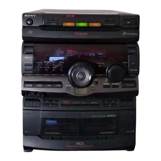
HCD-D90AV/GR10AV/
Photo : HCD-RX100AV : US model
Model Name Using Similar Mechanism
CD
CD Mechanism Type
SECTION
Base Unit Type
Optical Pick-up Type
TAPE
Model Name Using Similar Mechanism
DECK
Tape Transport Mechanism Type
SECTION
SPECIFICATIONS
COMPACT DISC DECK RECEIVER
— 1 —
RX100AV
US Model
HCD-D90AV/RX100AV
Canadian Model
AEP Model
UK Model
HCD-RX100AV
E Model
Australian Model
Tourist Model
HCD-GR10AV
HCD-H991AV
CDM38L-5BD29AL
BU-5BD29AL
KSS-213D/Q-NP
HCD-H991AV
TCM-220WR2
— Continued on next page —
Advertisement
Table of Contents

Related Manuals for Sony HCD-RX100AV


Summarization of Contents
Specifications Overview
Audio Power Specifications
Detailed power output and total harmonic distortion for U.S. models.
Amplifier Section Power Output
Power output details for various amplifier sections (AEP, UK, U.S., etc.).
Peak Music Power and Input Specifications
Peak music power output and input specifications for other models.
Tuner and General Specifications
Tuner Sections Tuning Ranges
Tuning ranges for UKV, FM (European/Other), and AM tuner sections.
General Unit Specifications
Details on power requirements, consumption, dimensions, and mass.
Safety Component Warning
Critical warning regarding safety components and their replacement.
Safety Procedures and Cautions
Safety Check-Out Procedures
Steps for safety checks after service before unit release to customer.
AC Leakage Measurement
Methods for measuring and limiting AC leakage current from metal parts.
Handling and Laser Safety Notes
Cautions on chip component replacement, circuit board repair, and laser safety.
Model Identification and Servicing Notes
Model Identification Reference
Reference for identifying models based on part numbers and country codes.
Laser Diode and Focus Operation Check
Procedure for checking laser diode emission and focus search operation.
Servicing and Disassembly Procedures
Servicing Note: Opening Disc Tray
Procedure to open the disc tray when the power switch is turned off.
Disassembly of Loading and Front Panels
Step-by-step guide for disassembling the loading and front panels.
Disassembly of Mechanism and Boards
Disassembly procedures for TC mechanism, deco board, and various other boards.
Disc Tray Removal Procedure
Instructions for removing the disc tray after the front panel disassembly.
Service Mode Operations
Reset and Delivery Modes
Procedures for MC cold reset, hot reset, and CD delivery mode.
Sled Servo and Function Name Change
Modes for sled servo control and changing the external input function name.
AM Tuner Step and Key Check Mode
Methods to change AM tuner step and activate key check mode.
Aging Mode Procedures
Aging Mode in CD Section
Procedure for checking CD section operation using aging mode.
Aging Mode in Tape Deck Section
Procedure for checking tape deck operation using aging mode.
Mechanical and Electrical Adjustments
Mechanical Adjustment Precautions
Precautions for cleaning, demagnetizing, and handling parts during mechanical adjustments.
Torque Measurement Specifications
Table detailing torque measurements for FWD, REV, and FF/REW.
Electrical Adjustment Guidelines
General guidelines and order for electrical adjustments.
Record/Playback Head Azimuth Adjustment
Procedure for adjusting the azimuth of record/playback heads.
Tape Deck Adjustment Procedures
Tape Speed Adjustment for Deck A
Procedure to adjust tape speed for Deck A using a test mode.
Playback Level Adjustment for Decks
Procedure to adjust playback level for both decks using test tape.
Tape Deck Recording Adjustments
Record Bias Adjustment for Deck B
Procedure for performing record bias adjustment using REC memory mode.
Record Level Adjustment for Deck B
Procedure for adjusting record level to achieve specified playback signal levels.
Tuner Section Adjustments
AM Tuned Level Adjustment Procedure
Procedure to adjust AM tuned level by tuning the set to specific frequencies.
FM Tuned Level Adjustment Procedure
Procedure to adjust FM tuned level by supplying a signal to 98 MHz.
FM Polar Adjustment
FM Polar Adjustment for Specific Models
Procedure for FM polar adjustment for East European and CIS models.
CD Section Checks and Adjustments
S Curve Waveform Check
Procedure to check the symmetrical S-curve waveform for focus search.
E-F Balance and RF Level Checks
Procedures for checking E-F balance and RF signal waveform and level.
Diagrams and Circuit Board Locations
Circuit Boards Location Overview
Diagrams showing the location of all major circuit boards within the unit.
Block Diagrams - Tuner Section
Tuner Section Block Diagram (AEP, UK, German)
Block diagram for the tuner section covering AEP, UK, and German models.
Block Diagrams - Tuner Section
Tuner Section Block Diagram (East European, CIS)
Block diagram for the tuner section for East European and CIS models.
Block Diagrams - CD Section
CD Section Block Diagram
Block diagram illustrating the CD section, including optical pick-up.
Block Diagrams - Deck Section
Deck Section Block Diagram
Block diagram of the deck section, showing heads, motors, and control logic.
Block Diagrams - Main Section
Main Section Block Diagram
Block diagram of the main section covering control, audio, and display.
Block Diagrams - Power Section
Power Section Block Diagram
Block diagram of the power section, illustrating power supply and amplifier circuits.
Printed Wiring Boards - CD Section
BD Board Printed Wiring Layout
Printed wiring board layout for the BD board (Side A and Side B) of the CD section.
Schematic Diagrams - CD Section
CD Section Schematic Diagram
Schematic diagram for the CD section, detailing component connections.
Tuner Section Diagrams (AEP, UK, German)
Tuner Section PWB Layout
Printed wiring board layout for the tuner section (AEP, UK, German models).
Tuner Section Schematic Diagram
Schematic diagram for the tuner section (AEP, UK, German models).
Tuner Section Diagrams (East European, CIS)
Tuner Section Schematic Diagram (EE, CIS)
Schematic diagram for the tuner section (East European, CIS models).
Tuner Section PWB Layout (EE, CIS)
Printed wiring board layout for the tuner section (East European, CIS models).
Printed Wiring Boards - Main Section
Main Board Printed Wiring Layout
Printed wiring board layout for the main board, detailing component placement.
Schematic Diagrams - Main Section
Main Board Schematic Diagram
Schematic diagram for the main board, showing circuitry for various functions.
Schematic Diagrams - Deck Section
Deck Section Schematic Diagram
Schematic diagram for the deck section, including audio and motor boards.
Printed Wiring Boards - Deck Section
Deck Section PWB Layout
Printed wiring board layout for the deck section, showing board connections.
Schematic Diagrams - Panel Section
Panel Section Schematic Diagram
Schematic diagram for the panel section, detailing various board connections.
Printed Wiring Boards - Panel Section
Panel Section PWB Layout
Printed wiring board layout for the panel section, showing board connections.
Schematic Diagrams - Power Section
Power Section Schematic Diagram
Schematic diagram of the power section, detailing amplifier and power supply circuits.
Printed Wiring Boards - Power Section
Power Section PWB Layout
Printed wiring board layout for the power section, including power and surround boards.
CD Motor Section Diagrams
CD Motor Section Schematic Diagram
Schematic diagram for the CD motor section, showing motor drive connections.
CD Motor Section PWB Layout
Printed wiring board layout for the CD motor section, illustrating board connections.
IC Block Diagrams - Tuner Section
Tuner IC Block Diagrams (LC72130, LA1835)
Block diagrams for IC21 (LC72130) and IC41 (LA1835) in the tuner section.
IC Block Diagrams - Tuner Section
Tuner IC Block Diagrams (IR3R42, BU1922)
Block diagrams for IC1701 (IR3R42) and IC1752 (BU1922) in the tuner section.
IC Block Diagrams - CD Section
CD Section IC101 CXA1992AR Block Diagram
Block diagram for IC101 (CXA1992AR), the servo controller for the CD section.
IC Block Diagrams - CD Section
CD Section IC102 BA5941FP & IC103 CXD2519Q Diagrams
Block diagrams for IC102 (BA5941FP) and IC103 (CXD2519Q) in the CD section.
IC Block Diagrams - Main Section
Main Section IC Block Diagrams
Block diagrams for main section ICs: MC14052BCP, MC14053BCP, LB1641, LV1016.
IC Block Diagrams - Audio & Control
Audio & Control IC Block Diagrams
Block diagrams for IC601 (LA2786), IC604 (TC9210P), and IC901 (LA5617).
IC Block Diagrams - Power, Deck, Motor
Power, Deck, Motor IC Block Diagrams
Block diagrams for IC301, IC602, IC701, and IC801.
IC Pin Functions - CD Servo IC
IC101 CXA1992AR Pin Functions
Detailed pin functions for IC101 (CXA1992AR), the servo RF amplifier.
IC Pin Functions - CD Servo IC
IC101 CXA1992AR Pin Functions (Continued)
Continuation of detailed pin functions for IC101 (CXA1992AR).
IC Pin Functions - CD DSP
IC103 CXD2519Q DSP Pin Functions
Detailed pin functions for IC103 (CXD2519Q), the digital signal processor.
IC Pin Functions - CD DSP
IC103 CXD2519Q DSP Pin Functions (Continued)
Continuation of detailed pin functions for IC103 (CXD2519Q).
IC Pin Functions - CD DSP
IC103 CXD2519Q DSP Pin Functions (Continued)
Further continuation of pin functions for IC103 (CXD2519Q).
IC Pin Functions - Display Control
IC601 TMP87CH75F Display Control Pin Functions
Detailed pin functions for IC601 (TMP87CH75F), the display control IC.
IC Pin Functions - Master Control
IC701 Master Control Pin Functions
Detailed pin functions for IC701 (uPD780018YGF-013-3BA), the master control IC.
IC Pin Functions - Master Control
IC701 Master Control Pin Functions (Continued)
Continuation of pin functions for IC701 (uPD780018YGF-013-3BA).
IC Pin Functions - Master Control
IC701 Master Control Pin Functions (Continued)
Further continuation of pin functions for IC701 (uPD780018YGF-013-3BA).
Exploded Views - Case Section
Case Section Exploded View
Exploded view of the unit's case section, showing part numbers and assembly.
Exploded Views - Main Board
Main Board Section Exploded View
Exploded view of the main board section, indicating components and placement.
Exploded Views - Main and Panel Boards
Main Board Parts List
Comprehensive list of parts for the main board, including part numbers.
Panel Board Section Exploded View
Exploded view of the panel board section, showing assembly details.
Exploded Views - Panel Board Section
Panel Board Section Exploded View
Detailed exploded view of the panel board section, illustrating component placement.
Exploded Views - Panel and Front Panel
Panel Board Parts List
List of parts for the panel board, including part numbers and descriptions.
Front Panel Section Exploded View
Exploded view of the front panel section, showing assembly of buttons and displays.
Exploded Views - Front Panel Section
Front Panel Section Parts List
List of parts for the front panel section, including part numbers and descriptions.
Exploded Views - TC Mechanism Section 1
TC Mechanism Section 1 Exploded View
Exploded view of the TC mechanism section 1 (TCM-220WR2), showing component assembly.
Exploded Views - TC Mechanism Section 2
TC Mechanism Section 2 Exploded View
Exploded view of the TC mechanism section 2 (TCM-220WR2), detailing assembly.
Exploded Views - CD Mechanism Section 1
CD Mechanism Section 1 Exploded View
Exploded view of the CD mechanism section 1 (CDM38L-5BD29AL), showing component layout.
Exploded Views - CD Mechanism Section 2
CD Mechanism Section 2 Exploded View
Exploded view of the CD mechanism section 2 (CDM38L-5BD29AL), detailing assembly.
Exploded Views - Base Unit Section
Base Unit Section Exploded View
Exploded view of the base unit section (BU-5BD29AL), showing optical pick-up.
Electrical Parts List - Audio Board
Audio Board Parts List
List of electrical parts for the audio board, including capacitors, ICs, and resistors.
Electrical Parts List - BD Section
BD Board Parts List
List of electrical parts for the BD board, including connectors, ICs, and resistors.
Electrical Parts List - CD SW Board
CD SW Board Parts List
List of electrical parts for the CD SW board, including transistors and resistors.
Electrical Parts List - Connectors, DECO, HP/MIC
Connector, DECO, HP/MIC Parts List
List of parts for connectors, DECO, and HP/MIC boards.
Electrical Parts List - Panel Section
Panel Board Parts List
List of electrical parts for the panel board, including capacitors and connectors.
Electrical Parts List - Main Section
Main Board Capacitor & Connector Parts
List of capacitors and connectors for the main board.
Electrical Parts List - Main Section
Main Board Diode, IC, Jack, Coil Parts
List of diodes, ICs, jacks, and coils for the main board.
Electrical Parts List - Main Section
Main Board Transistor & Resistor Parts
List of transistors and resistors for the main board.
Electrical Parts List - Main Section
Main Board Resistor Parts List
Continuation of the resistor list for the main board.
Electrical Parts List - Main Section
Main Board Resistor, Switch, Capacitor Parts
List of resistors, switches, and capacitors for the main board.
Electrical Parts List - Panel Section
Panel Board Switch, Resistor, Transistor Parts
List of switches, resistors, and transistors for the panel board.
Electrical Parts List - Panel Section
Panel Board Resistor & Vibrator Parts
Continuation of panel board parts list, including resistors and vibrator.
Electrical Parts List - Power Section
Power Board Capacitor, Diode, Connector Parts
List of capacitors, diodes, and connectors for the power board.
Electrical Parts List - Power Section
Power Board Fuse, Transistor, Resistor, Terminal Parts
List of fuses, transistors, resistors, and terminals for the power board.
Electrical Parts List - Power Section
Power Board Transistor, Resistor, Relay Parts
List of transistors, resistors, and relays for the power board.
Electrical Parts List - Sensor, Surround, TCB
Sensor and Surround Board Parts List
List of parts for sensor and surround boards, including resistors and transistors.
Electrical Parts List - TCB Section
TCB Board Capacitor, Diode, IC Parts
List of capacitors, diodes, and ICs for the TCB board.
Electrical Parts List - TCB Section
TCB Board Resistor, Transistor Parts
List of resistors and transistors for the TCB board.
Electrical Parts List - TCB Section
TCB Board Terminal, Vibrator, Filter Parts
List of terminals, vibrators, filters, connectors, and diodes for the TCB board.
Electrical Parts List - TCB Section
TCB Board Resistor, Transistor, Filter Parts
Continuation of TCB board parts list, including resistors and transistors.
Electrical Parts List - TC SW & Trans
TC SW Board Diode, Transistor, Resistor Parts
List of diodes, transistors, and resistors for the TC SW board.
Hardware List
Hardware List
List of screws, rings, wires, and other hardware used in the unit.
Need help?
Do you have a question about the HCD-RX100AV and is the answer not in the manual?
Questions and answers