Table of Contents
Advertisement
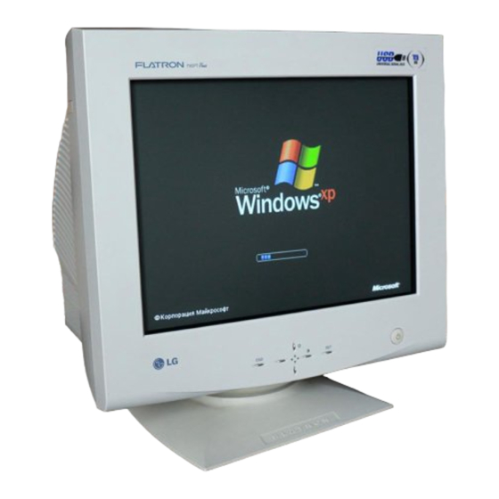
COLOR MONITOR
SERVICE MANUAL
CHASSIS NO. : CA-103
FACTORY MODEL: FB795E
MODEL:
*(
) ID LABEL Model No.
CAUTION
BEFORE SERVICING THE UNIT,
READ THE SAFETY PRECAUTIONS IN THIS MANUAL.
Website:http://biz.LGservice.com
E-mail:http://www.LGEservice.com/techsup.html
(
) 795FT Plus
795FT Plus
(FB795E-UP)
(FB795E-UA),
Advertisement
Table of Contents

Summarization of Contents
Safety Precautions
Safety-Related Component Warning
Critical safety components are marked. Replace with manufacturer-specified parts.
Safety Check
High voltage in deflection circuits requires caution during servicing.
Fire & Shock Hazard
Use isolation transformer, check soldering, reinstall protective devices carefully.
Implosion Protection
CRT tubes have built-in protection; avoid damage during installation.
X-Radiation Prevention
Prevent X-radiation by maintaining correct high voltage and using specified picture tube.
Operating Instructions
Front Control Panel Overview
Describes the function and operation of the monitor's front panel buttons.
Universal Serial Bus (USB)
USB Connection and Ports
Explains how to connect USB devices and identifies upstream/downstream ports.
Disassembly Procedures
Tilt/Swivel Removal
Steps to remove the monitor's tilt/swivel base.
Back Cover Removal
Instructions for removing the monitor's back cover.
Top Shield Removal
Guide for removing the top shield of the monitor.
Total Chassis Assembly Removal
Steps to remove the entire chassis assembly from the monitor.
Bottom Bracket Removal
Procedure to remove the bottom bracket of the monitor.
Main Bracket & Control PCB Assembly Removal
Steps to remove the main bracket and control PCB assembly.
Block Diagram Description
Line Filter & Associated Circuit
Suppresses noise on the power input line, preventing interference.
Degauss Circuit & Coil
Eliminates abnormal screen color by degaussing the slot mask.
SMPS (Switching Mode Power Supply)
Converts AC input voltage to various DC voltages for monitor operation.
Display Power Management Circuit
Controls monitor power consumption based on sync signals for energy saving.
X-ray Protection
Prevents X-radiation by monitoring and controlling high voltage levels.
Micom (Microprocessor) Circuit
Manages monitor functions, OSD controls, and stores user settings.
Horizontal and Vertical Synchronous Processor
Generates horizontal and vertical drive pulses from sync signals.
Oscillating Circuit for D/D Converter
Generates pulse waves for the D/D converter based on horizontal period.
D/D (DC to DC) Converter
Supplies DC voltage to deflection circuits by decreasing SMPS voltage.
Side-Pincushion Correcting Circuit
Improves screen side-pincushion distortion using east-west wave.
D/D Drive & Convert Circuit
Supplies B+ voltage to horizontal deflection transistor, adds side-pincushion correction.
Horizontal Deflection Output Circuit
Creates horizontal deflection by supplying saw-tooth current to the yoke.
High Voltage Output & FBT (Flyback Transformer)
Generates high voltage for the CRT anode using the FBT.
H-Linearity Correction Circuit
Corrects horizontal linearity based on horizontal sync frequency.
Vertical Output Circuit
Performs vertical deflection using signals from TDA9113 and TDA8172.
Dynamic Focus Output Circuit
Amplifies parabola waves for dynamic focus control to the FBT.
H & V Blanking and Brightness Control
Controls retrace line elimination and screen brightness via G1.
Image Rotation (Tilt) Circuit
Corrects screen tilt by supplying image rotation signal to the tilt coil.
Static Convergence Control Circuit
Corrects screen convergence by supplying signal to the STC coil.
Moire Reduction Circuit
Reduces interference from display patterns by fine-tuning video signal beams.
OSD Circuit
Manages the On-Screen Display function, showing adjustments when selected.
Video Pre-Amp Circuit
Amplifies incoming analog video signals for further processing.
Video Output Amp Circuit
Amplifies video signals for application to the CRT cathode.
Monitor Adjustments
General Information
Guidelines for performing monitor adjustments, including tools and warm-up time.
B+ Voltage Adjustment
Procedure to adjust B+ voltage to 190V ± 0.2V using VR901.
High-Voltage Adjustment
Procedure to adjust CRT anode voltage to 26kV ± 0.2kV using VR701.
Horizontal Raster Center Adjustment
Steps to center the horizontal raster using SW701.
Factory Mode (Preset Mode) Adjustment
Comprehensive adjustment process for factory preset modes using software.
White Balance and Luminance Adjustment
Adjusts white balance, luminance, brightness, and contrast using specific patterns and tools.
Focus Adjustment
Adjusts focus controls on the FBT for optimal picture clarity.
Troubleshooting Guide
No Power
Diagnostic flowchart for issues when the monitor does not power on.
No Character
Diagnostic steps for when no text or characters are displayed on the screen.
No Raster
Troubleshooting steps for when no image (raster) is displayed on the screen.
No Vertical Deflection
Diagnoses issues causing lack of vertical display, resulting in a horizontal line.
Trouble in DPM (Display Power Management)
Steps to troubleshoot issues with the monitor's power management system.
No Degaussing
Troubleshooting steps for the degaussing circuit when it fails to activate.
Trouble in OSD (On-Screen Display)
Diagnoses issues related to the monitor's On-Screen Display system.
Other Components
Miscellaneous Parts
Lists miscellaneous components like fuses, relays, transformers, switches, and connectors.
Pin Configurations
M24C08 EEPROM Pinout
Details the pin configuration and function of the M24C08 EEPROM IC.
HEF4013B Flip-Flop Pinout
Shows the pinout and block diagram for the HEF4013B Dual D Flip-Flop.
Integrated Circuit Details
KA358 Operational Amplifier
Pin configuration and block diagram for the KA358 dual operational amplifier.
TDA8172 Deflection Output Circuit
Pin configuration and block diagram for the TDA8172 vertical deflection output circuit.
KA431/A Voltage Regulator
Pin configuration and block diagram for the KA431/A voltage regulator.
STR-F6454R Switching Regulator
Pinout and block diagram for the STR-F6454R switching regulator power IC.
KA7805/KA7808/KA7812 Voltage Regulator
Pinout and block diagram for KA7805, KA7808, KA7812 voltage regulators.
Printed Circuit Boards (PCB)
Control Board Layouts
Shows component and solder sides of the control board.
Main Board Layouts
Displays component and solder sides of the main board.
Video Board Layouts
Illustrates component and solder sides of the video board.


Need help?
Do you have a question about the Flatron 795FT Plus (FB795E-UP) and is the answer not in the manual?
Questions and answers