
Related Manuals for Daikin RXYQ96


Summarization of Contents
Introduction
1.1 Safety Cautions
Crucial safety warnings and precautions for handling the equipment.
1.1.2 Cautions Regarding Products after Repair
Important cautions to follow after completing repair work.
1.1.3 Inspection after Repair
Steps for inspecting the system after repair work is completed.
Part 1 General Information
1. Model Names of Indoor/Outdoor Units
Lists model names for indoor and outdoor units.
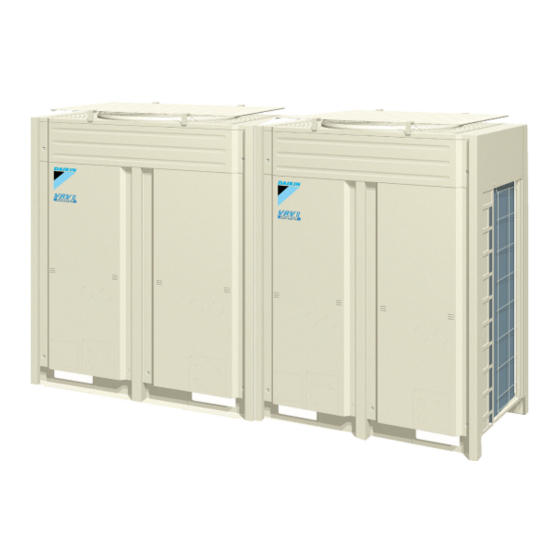
2. External Appearance
Describes the physical appearance of indoor and outdoor units.
3. Model Selection
Guides the selection of appropriate models based on requirements.
Part 2 Specifications
1. Specifications
Details the technical specifications of the equipment.
1.1 Outdoor Units
Provides detailed specifications for outdoor units.
1.2 Indoor Units
Provides detailed specifications for indoor units.
Part 3 Refrigerant Circuit
1. Refrigerant Circuit
Explains the refrigerant circuit diagram and components.
2. Functional Parts Layout
Shows the layout of functional parts within the outdoor unit.
3. Refrigerant Flow for Each Operation Mode
Illustrates refrigerant flow during different operation modes.
Part 4 Function
1. Operation Mode
Describes the system's various operating modes.
2. Basic Control
Explains fundamental control functions and parameters.
3. Special Control
Details specific control sequences for various conditions.
Part 5 Test Operation
1. Test Operation
Outlines the procedure for initial test operations after installation.
1.1 Procedure and Outline
Details the steps and overview of the test operation process.
1.2 Operation When Power is Turned On
Explains system behavior upon initial power-up sequences.
Part 6 Troubleshooting
1. Troubleshooting by Remote Controller
Methods for troubleshooting using the remote controller.
1.1 The INSPECTION / TEST Button
Explains the functionality of the Inspection/Test button on the remote.
1.2 Self-diagnosis by Wired Remote Controller
How to use the wired remote controller for self-diagnosis.
Troubleshooting by Indication on the Remote Controller
2. Troubleshooting by Indication on the Remote Controller
Guide to troubleshooting based on remote controller error indications.
2.1 “A0” Indoor Unit: Error of External Protection Device
Troubleshooting steps for "A0" error related to external protection devices.
2.2 “A1” Indoor Unit: PC Board Defect
Troubleshooting steps for "A1" error indicating a defective indoor unit PC board.
Troubleshooting
2.3 “A3” Indoor Unit: Malfunction of Drain Level Control System (S1L)
Troubleshooting for "A3" error related to drain level control system malfunction.
Troubleshooting
Flowchart for diagnosing "A3" errors related to drain pump and float switch issues.
Troubleshooting by Indication on the Remote Controller
2.4 “A6” Indoor Unit: Fan Motor (M1F) Lock, Overload
Troubleshooting for "A6" error indicating fan motor lock or overload.
2.5 “A7” Indoor Unit: Malfunction of Swing Flap Motor (MA)
Troubleshooting for "A7" error indicating swing flap motor malfunction.
Troubleshooting
Flowchart for diagnosing "A7" errors related to swing flap motor and related components.
Troubleshooting by Indication on the Remote Controller
2.6 “A9” Indoor Unit: Malfunction of Moving Part of Electronic Expansion Valve (20E)
Troubleshooting for "A9" error related to electronic expansion valve moving parts.
∗1 Coil check method for the moving part of the electronic expansion valve
Method for checking continuity of the electronic expansion valve's moving part.
Troubleshooting by Indication on the Remote Controller
2.7 “AF” Indoor Unit: Drain Level above Limit
Troubleshooting for "AF" error indicating the drain level is above the limit.
2.8 “AJ” Indoor Unit: Malfunction of Capacity Determination Device
Troubleshooting for "AJ" error related to capacity determination device issues.
Troubleshooting by Indication on the Remote Controller
2.9 “C4” Indoor Unit: Malfunction of Thermistor (R2T) for Heat Exchanger
Troubleshooting for "C4" error related to the heat exchanger thermistor.
2.10 “C5” Indoor Unit: Malfunction of Thermistor (R3T) for Gas Pipes
Troubleshooting for "C5" error related to the gas pipe thermistor.
Troubleshooting by Indication on the Remote Controller
2.11 “C9” Indoor Unit: Malfunction of Thermistor (R1T) for Suction Air
Troubleshooting for "C9" error related to the suction air thermistor.
2.12 “CJ” Indoor Unit: Malfunction of Thermostat Sensor in Remote Controller
Troubleshooting for "CJ" error related to the remote controller's thermostat sensor.
Troubleshooting by Indication on the Remote Controller
2.13 “E1” Outdoor Unit: PC Board Defect
Troubleshooting for "E1" error indicating an outdoor unit PC board defect.
2.14 “E3” Outdoor Unit: Actuation of High Pressure Switch
Troubleshooting for "E3" error indicating high pressure switch actuation.
Troubleshooting by Indication on the Remote Controller
2.15 “E4” Outdoor Unit: Actuation of Low Pressure Sensor
Troubleshooting for "E4" error indicating low pressure sensor actuation.
2.16 “E5” Compressor Motor Lock
Troubleshooting for "E5" error indicating compressor motor lock.
Troubleshooting by Indication on the Remote Controller
2.17 “E6” Compressor Motor Overcurrent/Lock
Troubleshooting for "E6" error indicating compressor motor overcurrent or lock.
Troubleshooting
Flowchart for diagnosing "E6" errors related to compressor motor overcurrent.
Troubleshooting by Indication on the Remote Controller
2.18 “E7” Malfunction of Outdoor Unit Fan Motor
Troubleshooting for "E7" error indicating outdoor unit fan motor malfunction.
Troubleshooting
Flowchart for diagnosing "E7" errors related to the outdoor fan motor.
Troubleshooting by Indication on the Remote Controller
2.19 “E9” Outdoor Unit: Malfunction of Moving Part of Electronic Expansion Valve (Y1E, Y2E)
Troubleshooting for "E9" error related to electronic expansion valve moving parts.
∗1 Coil check method for the moving part of the electronic expansion valve
Method for checking continuity of the electronic expansion valve's moving part.
Troubleshooting by Indication on the Remote Controller
2.20 “F3” Outdoor Unit: Abnormal Discharge Pipe Temperature
Troubleshooting for "F3" error indicating abnormal discharge pipe temperature.
2.21 “F6” Refrigerant Overcharged
Troubleshooting for "F6" error indicating refrigerant overcharge.
Troubleshooting by Indication on the Remote Controller
2.22 “H7” Abnormal Outdoor Fan Motor Signal
Troubleshooting for "H7" error indicating an abnormal outdoor fan motor signal.
∗1: Disconnect connector (X2A) and measure the following resistance.
Method for checking fan motor connector resistance values.
Troubleshooting by Indication on the Remote Controller
2.23 “H9” Outdoor Unit: Malfunction of Thermistor (R1T) for Outdoor Air
Troubleshooting for "H9" error related to the outdoor air thermistor.
∗1: Refer to thermistor resistance / temperature characteristics table on P239.
Reference to thermistor resistance data.
Troubleshooting by Indication on the Remote Controller
2.24 “J2” Current Sensor Malfunction
Troubleshooting for "J2" error indicating a current sensor malfunction.
2.25 “J3” Outdoor Unit: Malfunction of Discharge Pipe Thermistor (R31~33T)
Troubleshooting for "J3" error related to the discharge pipe thermistor.
Troubleshooting by Indication on the Remote Controller
2.26 “J5” Outdoor Unit: Malfunction of Thermistor (R2T) for Suction Pipe
Troubleshooting for "J5" error related to the suction pipe thermistor.
2.27 “J6” Outdoor Unit: Malfunction of Thermistor (R4T) for Outdoor Unit Heat Exchanger Deicer
Troubleshooting for "J6" error related to the heat exchanger deicer thermistor.
Troubleshooting by Indication on the Remote Controller
2.28 “J7” Malfunction of Receiver Outlet Liquid Pipe Thermistor (R6T)
Troubleshooting for "J7" error related to the receiver outlet liquid pipe thermistor.
2.29 “J8” Malfunction of Oil Equalizing Pipe Thermistor (R7T)
Troubleshooting for "J8" error related to the oil equalizing pipe thermistor.
Troubleshooting by Indication on the Remote Controller
2.30 “J9” Malfunction of Sub-Cooling Gas Pipe Thermistor (R5T)
Troubleshooting for "J9" error related to the sub-cooling gas pipe thermistor.
2.31 “JA” Outdoor Unit: Malfunction of Discharge Pipe Pressure Sensor
Troubleshooting for "JA" error related to the discharge pipe pressure sensor.
Troubleshooting by Indication on the Remote Controller
2.32 “JC” Outdoor Unit: Malfunction of Suction Pipe Pressure Sensor
Troubleshooting for "JC" error related to the suction pipe pressure sensor.
∗1: Voltage measurement point
Diagram showing voltage measurement points for pressure sensors.
Troubleshooting by Indication on the Remote Controller
2.33 “L4” Outdoor Unit: Malfunction of Inverter Radiating Fin Temperature Rise
Troubleshooting for "L4" error related to inverter radiating fin temperature rise.
2.34 “L5” Outdoor Unit: Inverter Compressor Abnormal
Troubleshooting for "L5" error indicating an abnormal inverter compressor.
Troubleshooting by Indication on the Remote Controller
2.35 “L8” Outdoor Unit: Inverter Current Abnormal
Troubleshooting for "L8" error indicating abnormal inverter current.
Troubleshooting Output current check
Flowchart for checking output current and diagnosing inverter issues.
Troubleshooting by Indication on the Remote Controller
2.36 “L9” Outdoor Unit: Inverter Start up Error
Troubleshooting for "L9" error indicating an inverter startup error.
2.37 “LC” Outdoor Unit: Malfunction of Transmission Between Inverter and Control PC Board
Troubleshooting for "LC" error related to communication between inverter and control PC boards.
Troubleshooting by Indication on the Remote Controller
Troubleshooting
Flowchart for diagnosing "LC" communication errors between inverter and control PC boards.
2.38 “P1” Outdoor Unit: Inverter Over-Ripple Protection
Troubleshooting for "P1" error related to inverter over-ripple protection.
Troubleshooting by Indication on the Remote Controller
2.39 “P4” Outdoor Unit: Malfunction of Inverter Radiating Fin Temperature Rise Sensor
Troubleshooting for "P4" error related to the inverter radiating fin temperature sensor.
2.40 “PJ” Outdoor Unit: Faulty Field Setting after Replacing Main PC Board or Faulty Combination of PC Board
Troubleshooting for "PJ" error due to incorrect field settings or PC board combinations.
Troubleshooting by Indication on the Remote Controller
Troubleshooting
Flowchart for diagnosing "PJ" errors related to PC board replacement or combination.
2.41 “U0” Outdoor Unit: Low Pressure Drop Due to Refrigerant Shortage or Electronic Expansion Valve Failure
Troubleshooting for "U0" error indicating low pressure due to refrigerant or EV failure.
Troubleshooting by Indication on the Remote Controller
Troubleshooting
Flowchart for diagnosing "U0" errors related to low pressure and refrigerant.
2.42 “U1” Outdoor Unit: Reverse Phase, Open Phase
Troubleshooting for "U1" error related to reverse or open phase power supply.
Troubleshooting by Indication on the Remote Controller
2.43 “U2” Outdoor Unit: Power Supply Insufficient or Instantaneous Failure
Troubleshooting for "U2" error indicating insufficient or intermittent power supply.
2.44 “U3” Outdoor Unit: Check Operation not executed
Troubleshooting for "U3" error when check operation is not executed.
Troubleshooting by Indication on the Remote Controller
2.45 “U4” Malfunction of Transmission Between Indoor Units and Outdoor Units
Troubleshooting for "U4" error related to transmission issues between indoor and outdoor units.
Troubleshooting
Flowchart for diagnosing "U4" transmission errors between indoor and outdoor units.
Troubleshooting by Indication on the Remote Controller
2.46 “U5” Indoor Unit: Malfunction of Transmission Between Remote Controller and Indoor Unit
Troubleshooting for "U5" error related to communication between remote controller and indoor unit.
Troubleshooting
Flowchart for diagnosing "U5" communication errors between remote controllers and indoor units.
Troubleshooting by Indication on the Remote Controller
2.47 “U7” Indoor Unit: Malfunction of Transmission Between Outdoor Units
Troubleshooting for "U7" error related to transmission issues between outdoor units.
2.48 “U8” Indoor Unit: Malfunction of Transmission Between Main and Sub Remote Controllers
Troubleshooting for "U8" error related to communication between main and sub remote controllers.
Troubleshooting by Indication on the Remote Controller
2.49 “U9” Indoor Unit: Malfunction of Transmission Between Indoor Units and Outdoor Units in the Same System
Troubleshooting for "U9" error related to transmission between indoor/outdoor units in the same system.
Troubleshooting
Flowchart for diagnosing "U9" transmission errors involving multiple indoor units.
Troubleshooting by Indication on the Remote Controller
2.50 “UA” Improper Combination of Indoor Units and Outdoor Units/Indoor Units and Remote Controller
Troubleshooting for "UA" error due to improper unit or controller combinations.
Troubleshooting
Flowchart for diagnosing "UA" errors related to improper unit or controller combinations.
Troubleshooting by Indication on the Remote Controller
2.51 “UC” Address Duplication of Central Remote Controller
Troubleshooting for "UC" error indicating address duplication in central remote controllers.
Troubleshooting
Flowchart for diagnosing "UC" address duplication errors with central controllers.
Troubleshooting by Indication on the Remote Controller
2.52 “UE” Malfunction of Transmission Between Centralized Controller and Indoor Unit
Troubleshooting for "UE" error related to transmission between centralized controller and indoor units.
Troubleshooting
Flowchart for diagnosing "UE" transmission errors with central controllers and indoor units.
Troubleshooting by Indication on the Remote Controller
2.53 “UF” System is not Set yet
Troubleshooting for "UF" error indicating the system configuration is not set.
Troubleshooting
Flowchart for diagnosing "UF" errors related to system setup and wiring.
Troubleshooting by Indication on the Remote Controller
2.54 “UH” Malfunction of System, Refrigerant System Address Undefined
Troubleshooting for "UH" error indicating undefined system or refrigerant addresses.
Troubleshooting
Flowchart for diagnosing "UH" errors related to system and refrigerant addresses.
Troubleshooting (OP: Central Remote Controller)
3. Troubleshooting (OP: Central Remote Controller)
Troubleshooting guide for issues related to the central remote controller.
3.1 “M1” PC Board Defect
Troubleshooting for "M1" error indicating a defective PC board in the central controller.
3.2 “M8” Malfunction of Transmission Between Optional Controllers for Centralized Control
Troubleshooting for "M8" error related to transmission between optional controllers.
Troubleshooting (OP: Central Remote Controller)
Troubleshooting
Flowchart for diagnosing "M8" transmission errors with optional centralized controllers.
3.3 “MA” Improper Combination of Optional Controllers for Centralized Control
Troubleshooting for "MA" error due to improper combination of optional controllers.
Troubleshooting (OP: Central Remote Controller)
Troubleshooting
Flowchart for diagnosing "MA" errors related to optional controller combinations.
3.4 “MC” Address Duplication, Improper Setting
Troubleshooting for "MC" error due to address duplication or improper settings.
Troubleshooting (OP: Schedule Timer)
4. Troubleshooting (OP: Schedule Timer)
Troubleshooting guide for issues related to the schedule timer.
4.1 “UE” Malfunction of Transmission Between Central Remote Controller and Indoor Unit
Troubleshooting for "UE" error related to transmission between central controller and indoor units.
Troubleshooting
Flowchart for diagnosing "UE" transmission errors with central controllers and indoor units.
Troubleshooting (OP: Schedule Timer)
4.2 “M1” PC Board Defect
Troubleshooting for "M1" error indicating a defective schedule timer PC board.
4.3 “M8” Malfunction of Transmission Between Optional Controllers for Centralized Control
Troubleshooting for "M8" error related to transmission between optional controllers for centralized control.
Troubleshooting (OP: Schedule Timer)
Troubleshooting
Flowchart for diagnosing "M8" transmission errors with optional centralized controllers.
4.4 “MA” Improper Combination of Optional Controllers for Centralized Control
Troubleshooting for "MA" error due to improper combination of optional controllers.
Troubleshooting (OP: Schedule Timer)
Troubleshooting
Flowchart for diagnosing "MA" errors related to optional controller combinations.
4.5 “MC” Address Duplication, Improper Setting
Troubleshooting for "MC" error due to address duplication or improper settings in schedule timers.
Troubleshooting (OP: Unified ON/OFF Controller)
5. Troubleshooting (OP: Unified ON/OFF Controller)
Troubleshooting guide for unified ON/OFF controller issues.
5.1 Operation Lamp Blinks
Troubleshooting for errors indicated by blinking operation lamps.
Troubleshooting
Flowchart for diagnosing operation lamp blink errors with ON/OFF controllers.
Troubleshooting (OP: Unified ON/OFF Controller)
5.2 Display “Under Centralized Control” Blinks (Repeats Single Blink)
Troubleshooting for "Under Centralized Control" blink errors (single blink).
Troubleshooting
Flowchart for diagnosing "Under Centralized Control" blink errors (single blink).
Troubleshooting (OP: Unified ON/OFF Controller)
Troubleshooting
Flowchart for diagnosing "Under Centralized Control" blink errors (repeats single blink) and related issues.
5.3 Display “Under Centralized Control” Blinks (Repeats Double Blink)
Troubleshooting for "Under Centralized Control" blink errors (double blink).
Troubleshooting (OP: Unified ON/OFF Controller)
Troubleshooting
Flowchart for diagnosing "Under Centralized Control" blink errors (double blink).
Part 7 Replacement Procedure for INV Compressor, VRV
1. Replacement Procedure for INV Compressor, VRV (RXYQ72M, 96M)
Step-by-step guide for replacing the INV compressor.
1.1 Replacement Procedure
Detailed instructions for replacing the INV compressor.
Part 8 Appendix
1. Piping Diagrams
Visual representation of the system's refrigerant piping.
2. Wiring Diagrams for Reference
Electrical wiring diagrams for system components.
3. List of Electrical and Functional Parts
Catalog of electrical and functional parts used in the system.
Appendix
1. Piping Diagrams
Diagram showing the refrigerant piping for outdoor units.
1.2 Indoor Unit
Diagram illustrating the refrigerant piping for various indoor units.
FXDQ
Refrigerant pipe connection port diameters for FXDQ models.
Appendix
2. Wiring Diagrams for Reference
Wiring diagram for the RXYQ72, 96MTJU outdoor unit.
2.2 Field Wiring
Diagram illustrating field wiring connections for outdoor and indoor units.
RXYQ144, 168,192MTJU
Field wiring diagram for RXYQ144, 168, 192MTJU models.
Appendix
2.3 Indoor Unit
Wiring diagrams for various indoor unit types (FXFQ, FXDQ).
FXSQ, FXMQ
Wiring diagrams for FXSQ and FXMQ indoor units.
FXHQ, FXAQ
Wiring diagrams for FXAQ and FXHQ indoor units.
Appendix
FXLQ, FXNQ
Wiring diagrams for FXLQ and FXNQ indoor units.
List of Electrical and Functional Parts
3. List of Electrical and Functional Parts
Lists electrical and functional parts for outdoor units.
3.1 Outdoor Unit
Details electrical and functional parts for the outdoor unit.
3.1.1 RXYQ72M, 96MTJU
Specific parts list for RXYQ72M and 96MTJU outdoor units.
Appendix
3.2 Indoor Side
Lists electrical and functional parts for indoor units.
3.2 Indoor Side
Parts list for FXFQ, FXDQ indoor units.
FXSQ, FXMQ
Parts list for FXSQ and FXMQ indoor units.
List of Electrical and Functional Parts
FXHQ, FXAQ
Parts list for FXHQ and FXAQ indoor units.
FXLQ, FXNQ
Parts list for FXLQ and FXNQ indoor units.
Option List
4. Option List
Lists available optional accessories for the system.
4.1 Option List of Controllers
Lists optional controllers available for system operation.
Appendix
4.1 Option List of Controllers
Details optional controllers like remote controllers and adapters.
Building management system
Options for integrating with building management systems.
Appendix
4.2 Option Lists (Outdoor Unit)
Lists optional accessories specifically for outdoor units.
Example of Connection
5. Example of Connection
Provides examples of system connection configurations.
Appendix
6. Thermistor Resistance / Temperature Characteristics
Table showing thermistor resistance values at different temperatures.
7. Pressure Sensor
Details the characteristics of pressure sensors used in the system.
Method of Replacing The Inverter’s Power Transistors and Diode Modules
8. Method of Replacing The Inverter’s Power Transistors and Diode Modules
Procedure for replacing inverter power transistors and diode modules.
8.1 Method of Replacing The Inverter’s Power Transistors and Diode Modules
Detailed steps for replacing inverter power components.
Method of Replacing The Inverter’s Power Transistors and Diode Modules
Power Transistor IGBT (On Inverter PC Board)
Method for checking and replacing power transistors on the inverter PC board.
Diode Module
Method for checking and replacing the diode module.
Part 9 Precautions for New Refrigerant (R-410A)
1. Precautions for New Refrigerant (R-410A)
Important safety precautions when working with R-410A refrigerant.
1.1 Outline
General outline of precautions for R-410A refrigerant.
1.2 Service Tools
Lists specialized tools required for handling R-410A refrigerant.
Precautions for New Refrigerant (R-410A)
1. Precautions for New Refrigerant (R-410A)
Safety precautions for R-410A refrigerant.
1.1 Outline
Overview of R-410A refrigerant characteristics including performance, pressure, and composition.
1.1.1 About Refrigerant R-410A
Details properties of R-410A refrigerant including performance, pressure, and composition.
Precautions for New Refrigerant (R-410A)
Thermodynamic characteristic of R-410A
Table of thermodynamic properties for R-410A refrigerant.
Precautions for New Refrigerant (R-410A)
1.2 Service Tools
Lists required service tools and their compatibility with different refrigerants.
Tool compatibility
Table indicating compatibility of tools with R-410A, R-407C, and R-22.
Precautions for New Refrigerant (R-410A)
Copper tube material and thickness
Table detailing copper tube material and thickness requirements for different refrigerants.
1. Flaring tool
Information on flaring tools, including specifications and differences for R-410A.
Precautions for New Refrigerant (R-410A)
2. Torque wrench
Specifications and differences for torque wrenches used with R-410A.
3. Vacuum pump with check valve
Details on vacuum pumps, including specifications and adapters for HFCs.
Precautions for New Refrigerant (R-410A)
4. Leak tester
Information on leak testers, including types and applicable refrigerants.
5. Refrigerant oil
Details on refrigerant oil, its properties, and compatibility.
6. Gauge manifold for R-410A
Specifications for gauge manifolds used with R-410A.
Precautions for New Refrigerant (R-410A)
7. Charge hose for R-410A
Specifications and differences for charge hoses used with R-410A.
8. Weigher for refrigerant charge
Details on weighers for refrigerant charge, including accuracy and accessories.
Precautions for New Refrigerant (R-410A)
Regarding purchasing of service tools, please contact following address.
Contact information for purchasing service tools.
Precautions for New Refrigerant (R-410A)
Precautions for New Refrigerant (R-410A)
General precautions for handling new refrigerants.
Precautions for New Refrigerant (R-410A)
Precautions for New Refrigerant (R-410A)
General precautions for handling new refrigerants.
Part 9 Precautions for New Refrigerant (R-410A)
1. Precautions for New Refrigerant (R-410A)
Important safety precautions when working with R-410A refrigerant.
1.1 Outline
General outline of precautions for R-410A refrigerant.
1.2 Service Tools
Lists specialized tools required for handling R-410A refrigerant.
Precautions for New Refrigerant (R-410A)
1. Precautions for New Refrigerant (R-410A)
Safety precautions for R-410A refrigerant.
1.1 Outline
Overview of R-410A refrigerant characteristics including performance, pressure, and composition.
1.1.1 About Refrigerant R-410A
Details properties of R-410A refrigerant including performance, pressure, and composition.
Precautions for New Refrigerant (R-410A)
Thermodynamic characteristic of R-410A
Table of thermodynamic properties for R-410A refrigerant.
Precautions for New Refrigerant (R-410A)
1.2 Service Tools
Lists required service tools and their compatibility with different refrigerants.
Tool compatibility
Table indicating compatibility of tools with R-410A, R-407C, and R-22.
Precautions for New Refrigerant (R-410A)
Copper tube material and thickness
Table detailing copper tube material and thickness requirements for different refrigerants.
1. Flaring tool
Information on flaring tools, including specifications and differences for R-410A.
Precautions for New Refrigerant (R-410A)
2. Torque wrench
Specifications and differences for torque wrenches used with R-410A.
3. Vacuum pump with check valve
Details on vacuum pumps, including specifications and adapters for HFCs.
Precautions for New Refrigerant (R-410A)
4. Leak tester
Information on leak testers, including types and applicable refrigerants.
5. Refrigerant oil
Details on refrigerant oil, its properties, and compatibility.
6. Gauge manifold for R-410A
Specifications for gauge manifolds used with R-410A.
Precautions for New Refrigerant (R-410A)
7. Charge hose for R-410A
Specifications and differences for charge hoses used with R-410A.
8. Weigher for refrigerant charge
Details on weighers for refrigerant charge, including accuracy and accessories.
Precautions for New Refrigerant (R-410A)
Regarding purchasing of service tools, please contact following address.
Contact information for purchasing service tools.
Precautions for New Refrigerant (R-410A)
Precautions for New Refrigerant (R-410A)
General precautions for handling new refrigerants.
Drawings & Flow Charts
Drawings & Flow Charts
List of diagrams and flowcharts included in the manual.
Need help?
Do you have a question about the RXYQ96 and is the answer not in the manual?
Questions and answers