
Related Manuals for Siemens 351


Summarization of Contents
Introduction
1.1 Responsibility of the user for system configuration and functionality
Explains user's role in configuring and operating the motor starter system.
1.2 Required basic knowledge
Lists necessary knowledge areas for understanding the manual.
1.3 Scope
Defines the manual's coverage of SIRIUS 3RM1 motor starters and accessories.
1.4 Definition
Clarifies the term "3RM1 motor starter" used throughout the document.
1.5 Conformity
Lists standards the 3RM1 motor starters comply with.
1.6 Further documentation
Lists related Siemens manuals for further information.
1.7 Service&Support
Provides details on Siemens online support and resources.
1.8 DataMatrix code
Explains the DataMatrix code for device identification and information access.
1.9 Correction sheet
Instructions on how to provide feedback for manual improvements.
Product-specific safety information
2.1 General safety notes
Outlines general safety warnings and precautions for handling the devices.
2.2 Safety information for hazardous areas
Details safety considerations for installations in hazardous locations.
2.3 Safety instructions for safety-related applications
Provides critical safety guidance for implementing safety functions.
2.4 Intended use
Specifies the proper applications and conditions for using the product.
2.5 Current information about operational safety
Advises on staying updated with operational safety information.
2.6 Declaration of conformity
States compliance with EC Directives and applicable standards.
Description
3.1 Overview
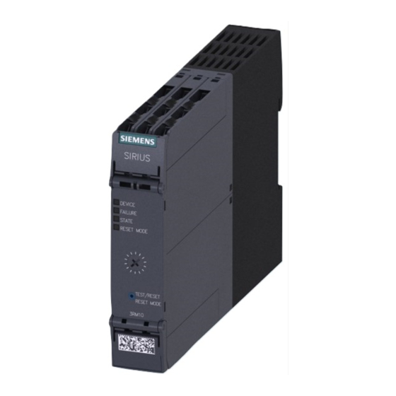
Introduces the SIRIUS 3RM1 motor starter and its basic features.
3.2 Applications
Lists typical areas and industries where the motor starters are used.
3.3 Hybrid technology
Explains the combination of semiconductor and relay technology in the starter.
3.4 Device versions
Details the different available versions of the 3RM1 motor starter.
3.5 Functions
Describes the various operational functions and protective features of the starter.
3.6 Accessories and order number scheme
Lists available accessories and explains the order number scheme.
Configuration
4.1 Rated operational current and derating
Explains how to set operational current and apply derating factors.
4.2 Ambient conditions
Details environmental factors like temperature, altitude, and mounting position.
4.3 Load feeders - protection against short circuit
Covers short-circuit protection methods and coordination types.
4.4 Infeed for the main circuit
Describes options for connecting the main power supply.
4.5 Configuration with device connectors
Explains how to configure the starter using device connectors.
4.6 Examples/applications
Presents typical circuit configurations and application examples.
Mounting
5.1 Warning notices
Provides essential safety warnings before installation and wiring.
5.2 Mounting the devices on a level surface
Step-by-step guide for mounting the device onto a flat surface.
5.3 Disassembling the devices from a level surface
Instructions for safely removing the device from a flat surface.
5.4 Mounting the devices on a standard mounting rail
Guide for mounting the device onto a standard DIN rail.
5.5 Disassembling devices from a standard mounting rail
Instructions for safely removing the device from a DIN rail.
5.6 Mounting the devices with device connectors on a standard mounting rail
Details mounting devices with connectors onto a standard mounting rail.
5.7 Disassembling the devices with device connectors from a standard mounting rail
Steps for safely removing devices with connectors from a DIN rail.
5.8 Mounting the devices with device connectors on a wall
Guide for mounting devices with connectors onto a wall surface.
5.9 Disassembling the devices with device connectors from a wall
Instructions for safely removing devices with connectors from a wall.
5.10 Mounting the sealable cover
Explains how to attach the sealable cover to protect settings.
Connection
6.1 Connecting the screw-type terminals
Step-by-step instructions for connecting screw-type terminals.
6.2 Disconnecting the screw-type terminals
Procedure for disconnecting screw-type terminals.
6.3 Connecting the push-in terminals
Guide for wiring using push-in spring-loaded terminals.
6.4 Disconnecting the push-in terminals
Instructions for safely disconnecting push-in terminals.
6.5 Attaching the terminals
Steps for attaching or replacing terminals on the device.
6.6 Removing the terminals
Procedure for removing terminals from the device.
6.7 Connecting the infeed system (option)
Details on connecting the optional infeed system.
Operator control and monitoring
7.1 Operator controls
Describes the buttons and switches for parameter assignment and operation.
7.2 Displays and location of the connections
Explains the device LEDs, terminal layout, and connection points.
Service and maintenance
8.1 Maintenance and service
Information on the maintenance-free nature of the devices.
8.2 Device replacement
Steps for replacing a defective device.
Technical data
9.1 Motor starters
Comprehensive technical specifications for the motor starter variants.
Dimension drawings
10.1 3RM1 dimension drawings
Provides detailed physical dimensions of the 3RM1 motor starter.
10.2 Dimension drawings for 3RM1 device connectors
Shows dimensional drawings for various 3RM1 device connectors.
Circuit diagrams
11.1 3RM10 circuit diagrams (direct-on-line starter, Standard)
Electrical circuit diagrams for 3RM10 standard direct-on-line starters.
11.2 3RM11 circuit diagrams (direct-on-line starter, Failsafe)
Circuit diagrams for 3RM11 failsafe direct-on-line starters.
11.3 3RM12 circuit diagrams (reversing starter, Standard)
Electrical circuit diagrams for 3RM12 standard reversing starters.
11.4 3RM13 circuit diagrams (reversing starter, Failsafe)
Circuit diagrams for 3RM13 failsafe reversing starters.
Typical circuits
A.1 Typical circuits for 3RM1 Standard
Illustrates common wiring configurations for 3RM1 Standard motor starters.
A.2 Typical circuits for 3RM1 Failsafe
Shows typical wiring configurations for 3RM1 Failsafe motor starters.
Directives
B.1 ESD Guidelines
Guidelines for handling electrostatic discharge sensitive components.
Need help?
Do you have a question about the 351 and is the answer not in the manual?
Questions and answers