Table of Contents
Advertisement
Quick Links
Siemens
Energy & Automation
AOUT1
AOUT2
AOUT3
DISCRETE OUTPUTS
DOUT1
RELAY OUTPUTS
ROUT1
ROUT2
LON WORKS
LONWORKS POWER SIGNAL COMMON
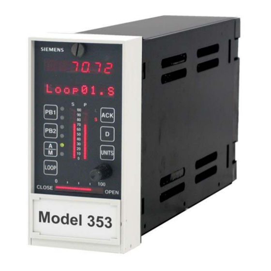
Model 353 Process Automation Controller
s
ANALOG OUTPUTS
s
2
T C2 0 5 3 . P
PB1
PB2
DOUT2
A
M
LOOP
0
CLOSE
NC
NO
NC
NO
Model 353
LIL
Multi-Purpose Training Panel
USER'S MANUAL
SIMULATED ANALOG INPUTS
AIN
AIN
AIN
4 2 . 4 5
3
AIN
S
P
100
L
ACK
S
80
UNIVERSAL ANALOG INPUTS
60
D
40
20
UNITS
0
b
AINU1
100
|
|
|
|
OPEN
b
AINU2
SIMULATED DISCRETE INPUTS
DIN2
DIN1
UNIVERSAL DISCRETE INPUTS
X03141S2
+
DINU1
CASE GROUND
for
UM353TP-1
Rev. 1
April 2002
AIN1
AOUT1
AIN2
AOUT2
AOUT3
AIN3
AIN4
NC
a
d
c
a
d
c
DIN3
DIN4
ON
OFF
-
-
+
DINU2
15990-60r2.dsf
Advertisement
Table of Contents

Related Manuals for Siemens 353


Summary of Contents for Siemens 353
- Page 1 LOOP RELAY OUTPUTS CLOSE OPEN ROUT1 AINU2 ROUT2 Model 353 SIMULATED DISCRETE INPUTS DIN2 DIN3 DIN4 DIN1 LON WORKS UNIVERSAL DISCRETE INPUTS X03141S2 DINU2 DINU1 LONWORKS POWER SIGNAL COMMON CASE GROUND 15990-60r2.dsf Multi-Purpose Training Panel Model 353 Process Automation Controller...
-
Page 3: Table Of Contents
UM353TP-1 Contents Table of Contents Section and Title Page 1.0 INTRODUCTION ............................. 1-1 1.1 PRODUCT DESCRIPTION ...........................1-1 1.2 SPECIFICATIONS............................1-2 1.3 PRODUCT SUPPORT ...........................1-3 1.4 EQUIPMENT DELIVERY AND HANDLING .....................1-4 1.4.1 Receipt of Shipment ..........................1-4 1.4.2 Storage ..............................1-4 1.5 RELATED PUBLICATIONS.........................1-4 2.0 INSTALLATION............................... - Page 4 User’s Manual. A copy of this manual accompanies the equipment. The current version of the manual, in Portable Document Format (PDF), can be downloaded from www.sea.siemens.com/ia/. For the purpose of this manual and product labels, a qualified person is one who is familiar with the installation,...
- Page 5 Siemens Energy & Automation, Inc. Other trademarks are the property of their respective owners. Siemens Energy & Automation, Inc. assumes no liability for errors or omissions in this document or for the application and use of the information included in this document.
- Page 6 Contents UM353TP-1 April 2002...
-
Page 7: Introduction
The Training Panel consists of a standard controller case with a specially designed front panel. Controls, connectors, and displays on the front panel are used to select and adjust inputs to and outputs from the controller. Model 353 assemblies are either ordered separately or supplied from the user’s spare parts stock. Typically, assemblies are installed in the case by the user. -
Page 8: Specifications
Engineering, operating, and servicing personnel can become skilled in the use and configuration of a Model 353 without the threat of a costly process upset. Possible uses of the Multi-Purpose Training Panel with a Model 353 include: operator training, configuration development, and controller checkout and calibration. -
Page 9: Product Support
- Installation environment Customers that have a service agreement are granted access to the secure area of the Siemens Internet site. This area contains a variety of product support information. When logging on, you will be prompted to enter your username and password. -
Page 10: Equipment Delivery And Handling
If it is found that some items have been damaged or are missing, notify the Process Instrumentation Division of Siemens Energy and Automation immediately and provide full details. In addition, damages must be reported to the carrier with a request for their on-site inspection of the damaged item and its shipping carton. -
Page 11: Installation
2-1 shows Training Panels with case option 2 and those with case option 4. These case options have different case rear connectors and case option 4 includes an Ethernet connector. Refer to the Model 353 User’s Manual UM353-1 Rev 9 or later for additional information about case options. -
Page 12: Installation Considerations
The power cable and plug are not shown in the figures. The Training Panel can be field wired for DC power. Refer to Section 2.4 in this manual. Install a controller in the Training Panel case. At minimum, a Model 353 Display Assembly and MPU Controller board must be installed. Install additional boards as required by the process simulation, training curriculum, or controller configuration to be developed or run. -
Page 13: Electrical Power Input
120/240 Vac service. To determine the correct electrical power input for a controller, perform the following steps. Refer to the “Maintenance” section of the Model 353 User’s Manual (UM353-1) for specific information on assembly installation and adding of option boards. -
Page 14: Controller Installation
UM353TP-1 2.5 CONTROLLER INSTALLATION For installation details, refer to Figure 2-2 in this manual and to the Maintenance section of the Model 353 User’s Manual, Rev. 9 or higher. 1. Place a grounding wrist strap around your wrist and attach the ground wire clip to the GND receptacle at the bottom right corner of Training Panel’s front panel. - Page 15 UM353TP-1 Installation Connector Cover* Ground Screw* Voltage Input, Approvals, and Warning Label* Warning and I/O Capacity Label* Mounting Clip, Top and Bottom* Nameplate* LIL or Ethernet Network Board I/O Expander Board RTC/CB or RCB Board Removable Portions of Accessory or Connectors* Option Boards Connector Socket...
- Page 16 Installation UM353TP-1 April 2002...
-
Page 17: Operation
This section describes the Multi-Purpose Training Panel’s controls and displays. The Training Panel can provide all I/O signals needed to configure and operate a Model 353 controller with or without the use of external process control devices. The controls, binding posts, and displays on the front of the Training Panel and the Ethernet connector at the back of the case provide access to the following signals: •... -
Page 18: Analog Outputs
UNIVERSAL ANALOG INPUTS DISCRETE OUTPUTS DOUT2 DOUT1 UNITS AINU1 LOOP RELAY OUTPUTS CLOSE OPEN ROUT1 AINU2 ROUT2 Model 353 SIMULATED DISCRETE INPUTS DIN3 DIN1 DIN2 DIN4 LON WORKS UNIVERSAL DISCRETE INPUTS X03141S2 DINU2 DINU1 LONWORKS POWER SIGNAL COMMON CASE GROUND... - Page 19 UM353TP-1 Operation CA S E GND FIGURE 3-2 Wiring Diagram, Multi-Purpose Training Panel April 2002...
-
Page 20: Digital (Discrete) Inputs
Operation UM353TP-1 3.3 DIGITAL (DISCRETE) INPUTS SIMULATED DISCRETE INPUTS Digital inputs for DIN1, DIN2, DIN3, and DIN4 are activated by four single-pole DIN2 DIN3 DIN4 DIN1 switches located at the lower right side of the Training Panel and labeled Simulated Discrete Inputs DIN1 through DIN4.
Need help?
Do you have a question about the 353 and is the answer not in the manual?
Questions and answers