Table of Contents
Advertisement
Quick Links
Siemens
Energy & Automation
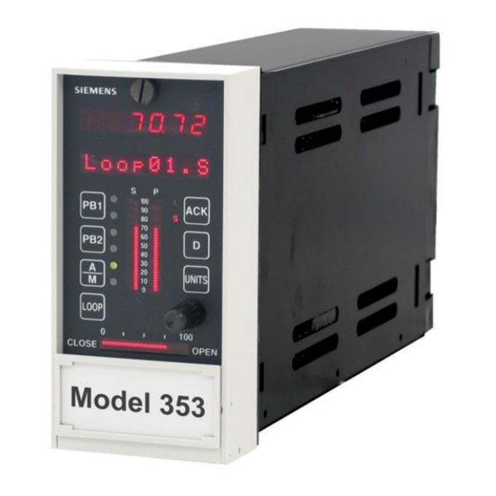
Model 353 Process Automation Controller
INVOLVED MANUALS
User's Manual, Model 353 Process Automation Controller, UM353-1, Rev. 8 and earlier.
DISCUSSION
Direct entry rear connectors will begin shipping in March 2001. Direct entry connectors are described in
this Addendum and all power, ground, station common, and signal terminals are identified.
Consult the nameplate on the case to determine whether direct entry connectors have been installed.
Model 353_2_ _ _ _ _ _ _ _ _ _ Side entry
Model 353_4_ _ _ _ _ _ _ _ _ _ Direct entry connectors with Ethernet connector are installed
Section 6 Installation, in UM353-1, describes the black side
entry connectors and the connections to be made to them. In
the following, the direct entry connectors will be described
and illustrated.
Direct entry connectors are shown in the adjacent figure.
There are four connectors with 52 screw-clamping terminal
connections. Each connector consists of a case mounted
portion and a plug-in portion. The plug-in portion of each
connector is securely fastened to the case mounted portion
by a screw at each end of the plug-in. The plug-in portion
can be completely wired and then plugged into the case
mounted portion.
Terminal functions and numbers have not changed. For
example, Station/Transmitter Common is terminal 6 on the
side entry and direct entry connectors.
A standard 8-wire Ethernet connector is provided near the
bottom of the assembly. A case ground screw is provided
near the top of the assembly, as in the side entry connectors.
The next page contains an illustration that states the
connections to the direct entry connectors.
1
Side entry and direct entry refer to the entry of wires into terminals installed on a rear connector assembly.
USER'S MANUAL ADDENDUM
1
Direct Entry
Rear Connectors
1
connectors are installed
UMA353-1-6
Rev. 1
April 2001
Advertisement
Table of Contents

Related Manuals for Siemens 353


Summary of Contents for Siemens 353
- Page 1 Direct Entry Rear Connectors INVOLVED MANUALS User’s Manual, Model 353 Process Automation Controller, UM353-1, Rev. 8 and earlier. DISCUSSION Direct entry rear connectors will begin shipping in March 2001. Direct entry connectors are described in this Addendum and all power, ground, station common, and signal terminals are identified.
- Page 2 UMA353-1-6 Terminal Function, ID, and Number Case/Safety Ground Network Communications A, NCA, 3 Network Communications B, NCB, 4 Transmitter Power 26 Vdc+, XMTR+, 5 Transmitter/Station Common, COM, 6 Transmitter Power, 26 Vdc+, XMTR+, 7 Digital Output 1+, DOUT1+, 8 Digital Outputs 1/2 Common, DOUTC, 9 Power Input Digital Output 2+, DOUT2+, 10 AC Hot or DC+, H...
- Page 3 UMA353-1-6 Wiring Guidelines Wire Size - Each terminal can accept: • one 12-24 AWG (2.5-0.2 mm • two 16 AWG (1.3 mm • three 18 AWG (0.96 mm Wire stripping length - 1/4" (6 mm) typical, 9/32" (7 mm) maximum. Terminal and ground screw torque: •...
- Page 4 Connectors Cover Siemens Energy & Automation, Inc. assumes no liability for errors or omissions in this document or for the application and use of information included in this document. The information herein is subject to change without notice. Procedures in this document have been reviewed for compliance with applicable approval agency requirements and are considered sound practice.
Need help?
Do you have a question about the 353 and is the answer not in the manual?
Questions and answers