Table of Contents
Advertisement
Quick Links
OPERATORS MANUAL
. MOBILE and INDUSTRIAL
I
. . . . .
...GENERATORS .
..
.
-
-
,.
r
-" •
. 8.0KW
BIOAR
10.0KW
BIOAR
.
.
12.5KW
BIOBR·
·15.0KW
BIOCR
14.0
CR
REVISION 2
WESTERBEKE CORPORATION '150 JOHN HANCOCK ROAD
MYLES STANDISH INDUSTRIAL PARK' TAUNTON
MA
02780
WEBSITE: WWW.WESTERBEKE.COM
..
...,~~
NMMA
Member National Marine Manufacturers Association
--
Advertisement
Table of Contents
Troubleshooting

Related Manuals for Westerbeke 12.5KW BTDBR


Summary of Contents for Westerbeke 12.5KW BTDBR
- Page 1 ..-" • BIOAR BIOAR . 8.0KW 10.0KW BIOBR· BIOCR 12.5KW ·15.0KW 14.0 REVISION 2 WESTERBEKE CORPORATION '150 JOHN HANCOCK ROAD MYLES STANDISH INDUSTRIAL PARK' TAUNTON 02780 WEBSITE: WWW.WESTERBEKE.COM ...,~~ NMMA Member National Marine Manufacturers Association...
- Page 2 Shut down the unit and do not restart until it has been inspected and repaired. A WARNING DECAL is provided by to a WESTERBEKE and should be fixed bulkhead near your engine generator. WESTERBEKE also recommends installing CARBON MONOXIDE DETECTORS.
- Page 3 Use a suitable container catch all fuel when removing the fuel line, carburetor, or fuel filters. -..v WESTERBEKE Engines & Generators...
- Page 4 • Do not run engines for long periods with their enclosures install a carbon monoxide detector. Consult your dealer open. for installation of approved detectors. WARNING: 00 not work on machinery when you are mentally or physically incapacitated by tatigue! WESTERBEKE ...v' Engines & Generators...
-
Page 5: Table Of Contents
TABLE OF CONTENTS Parts Identification ..........Engine Troubleshooting [Chart] ......28 Introduction ............Engine Adjustme·nts ..: ........Warranty Procedures .........3 Valve Clearance Adjustment ......30 Serial Number Location ........4 Testing Engine Compression ......31 Fuel Injectors ..........31 Diesel Fuel, Engine Oil, and Coolant .... -
Page 6: Parts Identification
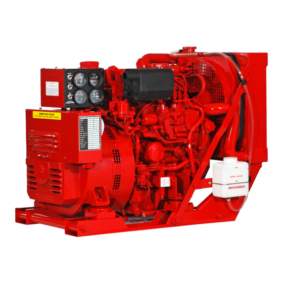
PARTS IDENTIFICATION STOP SWITCH AIR INTAKE/AIR FILTER ;REMOTE PANEL CHARGING ALTERNATOR .~SSEMBLY ~~l----:;:;J~- START MOTOR MOUNT FRONT • LEFT SIDE OIL SUMP _ _ _ _ _ _ ~-i~OOLANT PRESSURE CAP ,RADIATOR OIL FILL EXHAUST RIGHT SIDE 20A CIRCUIT J---EN'''N. SERIAL NUMBER REAR... -
Page 7: Introduction
INTRODUCTION This WESTERBEKE Diesel Generator is a product of PRODUCT SOFTWARE WESTERBEKE's long years of experience and advanced Product software, (tech data, parts lists, manuals, technology. We take great pride in the superior durability and brochures and catalogs), provided from sources other than dependable perfonnance of our engines and generators. -
Page 8: Serial Number Location
NOTE: A carbon monoxide warning decal has been provided by WESTERBEKE. Affix this decal in a visible position in the The engine and generator serial numbers and model numbers are located on a decal on the generator housing. Take the engine room. -
Page 9: Diesel Fuel, Engine Oil, And Coolant
A coolant recovery tank kit is supplied with each NOTE: information above supersedes all previous state- WESTERBEKE diesel engine. The purpose of this recovery ments regarding synthetic oil. tank is to allow for engine coolant expansion and contraction For recommended oil viscosity see the following chart·... -
Page 10: Generator Control Panels
To stop the engine, depress the STOP switch. When the STOP switch is depressed, the power feed to the fuel sole- WESTERBEKE noid is opened, and the fuel flow to the engine is stopped. The STOP switch should be depressed until the generator stops rotating NOTE: For additional infonnation on Control Panels. -
Page 11: Preparations For Initial Start-Up
Follow the procedures as presented for be switched OFF until the engine has come up tii speed the conditions indicated and your WESTERBEKE generator and, in cold climates, starts to warm up. This precaution set will give reliable performance and long service life. -
Page 12: Starting/Stopping Procedure
600 This system is common to WESTERBEKE diesels. The start rpm. This indicates when tbe START switch can be released circuitry is desigued so tbat tbe PREHEAT button must be since tbe starting of tbe generator may not be audible. -
Page 13: Safety Shutdown Switches
K2 relay is terminated. If this should occur, check and repair the source of the problem. After repairing the fault, reset the breaker and restart the generator. "'" WESTERBEKE Engines & Generators... -
Page 14: Generator Break-In Procedure
00 not attempt to break-in your generator by running without load. After the first 10 hours of the generator's operation, the load can be increased to the full-load rated output, then periodically vary the load. """ WESTERBEKE Engines & Generators... -
Page 15: The Daily Operation
Remove the major AC loads from the generator one at a time. Allow the generator to run for a few minutes to stabilize the operating temperature and depress the stop switch. (See STOPPING PROCEDURES on previous manu- als). WESTERBEKE Engines Generators &... -
Page 16: Maintenance Schedule
MAINTENANCE SCHEDULE WARNING: Never attempt to perform any service while the engine is running. Wear,theproper safety equipment such as goggles and gloves, and use the correct tools for each job. Disconnect the battery terminals when servicing any of the engine's electrical equipment. - Page 17 At first 50 hours, then every 500 hours (see Hold-down bolts ENGINE ADJUSTMENTS). "Adjust the Valve Clearances Adjust Valve Clearances (see ENGINE ADJUSTMENTS). "Radiator Remove, have professionally cleaned and pressure tested. "WESTERBEKE recommends this service be performed by an authorized mechanic. Engines & Generators...
-
Page 18: Cooling System
When the engine is started cold, external coolant flow is prevented by the closed thermostat (although some coolant Westerbeke diesel engines are designed and equipped for flow is bypassed around the thermostat to prevent the engine fresh water cooling. Heat produced in the engine by manifold from overheating). -
Page 19: Thermostat
As the engine warms up, the thermostat gradually opens. The thermostat is accessible and can be checked, cleaned, or replaced easily. Carry a spare thermostat and gasket. INTAKE SILEN.CER WESTERBEKE Engines & Generators... -
Page 20: Fuel System
This process is accomplished by installing and , maintaining a proper fuel filter/water separator betwen'the any fuel that may spill. DO NOT allow any smoking, , fuel tank and the generator/engine. Westerbeke recommends open flames or othe~-sources of fire near the fuel a 10 micron filter be used. -
Page 21: Engine Lubricating Oil
ENGINE LUBRICATING OIL LUBRICATlliN DIAGRAM When removing the used oil 2. Replacing the 011 Fl1ter. filter, you may find it helpful and cleaner to punch a hole in the upper and lower portion of the old filter to drain the OIL PRESSURE oil from it into a container before removing it. -
Page 22: Remote Oil Filter
Contact your WESTERBEKE dealer for more information. engine room bulkhead. NOTE: Westerbeke is not responsible for engine failure due to NOTE: Refer to ENGINE OIL CHANGE in this manual for incorrect installation of the Remote Oil Filter. -
Page 23: Oil Pressure
OIL PRESSURE DESCRIPTION TESTING OIL PRESSURE To test the oil pressure, remove the oil pressure sender, then The lubricating system is a pressure feeding system using install a mechanical oil pressure gauge in it's place. After an oil pump. The engine oil is drawn from the oil sump by warming up the engine, set the engine speed at 1800 the oil pump, which drives the oil, under pressure, through... -
Page 24: Dc Electrical System
Always isolate DC and AC converters, and shut down the 999999 (IGNITION ON • ENGINE OFF )"1'" engine before performing DC testing. No AC tests should ~='] be made without proper knowledge of AC circuits. STARTIN G BATTERY '<"- GROUND , . WESTERBEKE Engines &. Generators... -
Page 25: 12 Volt Dc Control Circuit
Sulfuric acid in lead batteries can cause severe burns on skin and damage clothing. Wear CAUTION: protective gear. To avoid damaging the alternator diodes, do not use high voltage tester (i.e. megger) when performing tests on the alternator charging circuit. -.v WESTERBEKE Engines & Generators... -
Page 26: Starter Motor
STARTER MOTOR SOLENOID DESCRIPTION The starting system includes the battery, starter motor, solenoid, and starter button. When the starter button on the instrument panel is depressed, current flows and energizes the starter's solenoid coil. The ')-:l~---(M) TERMINAL energized coil becomes an electromagnet, which pulls the plunger IGNITION into the coil, and closes a set of contacts which allow high cunent TERMINAL... -
Page 27: Service
STARTER MOTOR SERVICE Westerbeke uses a standard marine starter motor which can be POSITIVE servieed or rebuilt at any starter motor automotive service center. If replacing the starter motor, make certain the new motor is eertified for marine use. Automotive starters do not meet USCG standards. -
Page 28: Glow Plugs
GLOW PLUGS DESCRIPTION Re-install the plugs in the engine and test them again. The plugs should get very hot (at the terminal end) within 7 to 15 The glow plugs are wired through the preheat solenoid. seconds. the plugs don't heat up quickly, check for a short When PREHEAT is pressed at the control panel this solenoid circuit. -
Page 29: Generator Wiring Diagram #44744
\ GENERATOR ·WI_RING DIAGRAM '#44l44 AL TERNATOR 40A 24VDC WAHR T'MPFRATUR' ""j AI TfRNATOR SOA !2yO, WATER TEMPERATURE lli!Qll (" .. '"", ... PlU~ pr~ OM! ,LOI r-------------~--~--------------~~ ~----~~~--_d--~~20~A~C~IR~C~U~'T~~--~~----_+--~~ BREMFR- 12vpe PRESSllRf SENDER BATTfRYSWITCH ,RF! L!!:~ n)~L-",-",,,,,,,,u~.,,~,S2~I' U~ITI U----, AUX. OIL PRESSURE SWITCH ~TER S~lm,... -
Page 30: Generator Wiring Schematic
STOP SWITCH PREHEAT STA.RT SWITCH OIL PRESS. GAUGE IHD. LIGHT --?'"-- 1-:::':', .-~~ L __ I - >\-- f----1 lc;j -T!PICAl RE~OH START/STOP PANEL CO"(CTIONS- ~OTE. VOLTMETER OREMOTt: CONECTOR PINS - >t-- f----1 to:J L& WESTERBEKE -..v' Engines & Generators... -
Page 31: Remote Instrument Panel
< ' - " - " - " _ . ' - " - " - " - ' . _ " - " - " - " - " - " - . _ .. _ .. - . P. N. 44336 WESTERBEKE Engines Generators &... -
Page 32: Generator Wiring Diagram #044927
GENERATOR WIRING DIAGRAM #044927 (OPTIONAL ELECTRONIC GOVERNING) AI TERt/AIOR AQA-?4VRC -0-- ,!,I TtB!!~TQR ~n~-I~yt!!: WATER~RhTl!RF """ 114 BRN ., •••• "'m,.,~ 110 ORN " " '" "''"'' L."",,,.,, ' ' ' ' ' ' ' . " " R:", ~ "'~""' H~:r ,"V~ B~rtKF~~~~~kc... -
Page 33: Generator Wiringschematic
HI-STARr RUAV ____ +-~r~-~~'r-~ ~~r~-'~l~e- _________________ AUX. C.P. SIIT(H OIL PRUS. UND<R TBI·2 162·2 WAHR iEMP. GAUGE r.., IND. tiGHT OIL PRESS. GAUGE -TYPICAL RENOH STARI/STOP PAHEL COH((1I0HS- NOH: VOL TMEHR CO~£CTOR REI«lH PINS HOURMEl£R WESTERBEKE . E'!gines & Generators 27,A... -
Page 34: Engine Troubleshooting [Chart]
5. Check for blockage, collapsed hose, carbon buildup at Exhaust system is restricted. exhaust elbow. 6. Pump water from 1uel tank(s); change filters and 6. Water in fuel. bleed fuel system. 7. Air intake obstruction. 7. Check air intake filter cartridge. I~/WESTERBEKE Engines Generators &... - Page 35 (Check for restrictions in exhaust system; check air intake.). ab. Improperly timed injectors or -valves or poor compression. 3c, Lack of air - check air inlake and air filter. Check for proper ventilation. 3d. Overload . WESTERBEKE Engines Generators &...
-
Page 36: Engine Adjustments
ENGINE ADJUSTMENTS NOTE: WESTERBEKE recommends that the following engine adjustments be performed by a competent engine mechanic. VALVE CLEARANCE ADJUSTMENT d. For 3 cylinder models, rotate the crankshaft 240 Make the following adjustments when the engine is cold. degrees to position the next cylinder in the firing order 1. -
Page 37: Testing Engine Compression
ENGINE ADJUSTMENTS NOTE: WESTERBEKE recommends that the following engine adjustments be perfonned by a competent engine mechanic. The information below is provided to assist the mechanic. TESTING ENGINE COMPRESSION FUEL INJECTORS Make certain Ihe oil level (dipstick) is at the correct level In case of severe vibrations and detonation noise, have Ihe and the air intake filter is clean. -
Page 38: Control Panel Troubleshooting [Chart]
(both plus and minus gauge and connect it to ground. See if the gauge reads full terminals), the ground side will not necessarily be connected scale, which is the normal reading for this situation. to the block. "'" WESTERBEKE E.I1JJ.ines Gener~~t?rs &... -
Page 39: Electronic Governor Adjustments
20% (9.6VDC I2VDC I4.4VDC). Ifvoltage will varies above or below these ranges, the controller not operate and the engine will run in an idle mode until ADJUSTMENT proper voltage is supplied to the controller. WESTERBEKE -..y' Engines & Generators... -
Page 40: Linear Actuator Troubleshooting [Chart]
MPU positioned marginally too far away from e. Check the position of the MPU. teeth giving erratic AC input to controller. Check resistance value 950 -1000 ohm If problems continue to persist, contact your WESTERBEKE dealer for additional assistance. WESTERBEKE Engines &... -
Page 41: Genremote Calibration
Switch), WhitelBlack is the Stop Switch, Black is Preheat, Orange is Oil Pressure, Red is Water . Temperature, Yellow is the ExhaustHigh Temperature Alarm [marine applications ouly) andBlacklRed, ',is the Start Button. , IMPORTANT! The ExhaustHigh Temp terminal is connected to the ESS terminal when it is not used. """ WESTERBEKE Engine!--,&' Generators... -
Page 42: Genremote Control Station
The alarm LED can be cleared by pressing the stop button or by restarting the unit. The Fail-Safe Protocols include: 1 - Oil Pressure 2 - Coolant Temperature '3 - Exhaust Over temperature KLIXON WESTERBEKE -..v- Engi~t!l!. & Generators... -
Page 43: Genremote Wiring Diagram
LAND BASED UNITS ESS TO EXH ..• ESS Whlte/Red STOP START PreHeat ..0 0 0 Exhaust --" all Press To Westerbeke Wire orange Water Temp Plug Hamess and Gerllem"'" BlACK GROUND RED/VIOlET ESS TEHminalBbck WHrrEJRED STOP WHITE PREHEAT... -
Page 44: Genremote Installation Oiagram
GenRe Baftery, Wat er Temp and Oil Pressure, NoACread[ ngs will be displayed and the r will not turn on, Run [ndicato Westerbeke 8 Wire Harness & Plug "' lloutBlack IOO@i] ToAC load L20ut While AC load can be connected... -
Page 45: Genremote Specifications
TEMPERATURE RANGE ............. THROUGH will NOTE: Each module support a maximum displays. No more than two (2) displays OffOUT should be daisy chained to one module output. The module supports two (2) separate display output lines. """ WESTERBEKE Eng/lle.1! Generators... -
Page 46: Generator Litformation
(split-phase) are not CARBON MONOXIDE DETECTOR mode in larger sizes. WESTERBEKE recommends mounting a carbon monoxide Because the heavy surge of current needed for starting detector in the living quarters. Carbon Monoxide, even in... -
Page 47: Power Take Off Systems
WESTERBEKE COMMERCIAL GENERATOR for additional infonnation. SUPPUER XRT POWER SYSTEM power system combined with a Westerbeke generator provides electrical and hydraulic power for fire/emergency apparatus The system generates electrical power for auxiliary lighting and provides continuous operation of up to extrication tools at the sarne time. -
Page 48: Bt Generator
BT GENERATOR A circuit breaker is installed on all WESTERBEKE genera- This generator is a four-pole, brushIess, self-excited generator which requires only the driving force of the engine to pro- tors.'This circuit breaker will automatically disconnect gener- ator power in case of an electrical overload. The circuit duce AC output. -
Page 49: Bt Generator Single Phase
BT GENERATOR SINGLE PHASE [SIX STUDI 50 Hz TERMINAL r-------------------l ~~~==t=====~====: \ 60 Hz TERMINAL _-+ ___ :·~rn~-7 L _______________ A.v.R. 50cyc; REDfWHtTE (TO HERTZNOLTS SAR) , I"m PLUG BLUE {WHITe aRlaEN ,,,,----, """..""--4'--++-., {TO PIN #8TERM. -t~~i-~:jt- ' W H' " \ YElLOW SLUE tWHITe YE"... - Page 50 Use the compound transformer for this function. Using the regulator board. the regulator to perform this causes the regulator to use more exciter circuit power. This leaves less exciter circuit power for loacled conditions. """ WESTERBEKE Engines Generators &...
-
Page 51: Generator Voltage Adjustment
GENERATOR VOLTAGE ADJUSTMENT NOTE: WESTERBEKE recommends tiull the following generator tests and adjustments be performed by a quai/ijied technician. Generator Frequency d. After the no-load hertz adjustment is made, the no-load voltage may need be readjusted. In most cases, if the 1. - Page 52 GENERATOR VOLTAGE ADJUSTMENT NOTE: WESTERBEKE recommends that the following generator tests and adjustments be peifonned a quailified technician. FULL-LOAD VOLTAGE ADJUSTMENT NO-LOAD VOLTAGE ADJUSTMENT The voltage hertz connection bar that is used when changing Voltage adjusttnent is made with the generator regulation being governed by the compound transfOlmer.
-
Page 53: Bt Generator Voltage Regulator
3. Increase the engine speed to its normal speed (frequency). The red "LED" light will go out and the AC voltage out- Slab Volt put will return to normal. " With the above adjusnnents made, the regulator should func- tion normally. VOLTAGE REGULATOR DIAGRAM WESTERBEKE Engines & Generators... -
Page 54: Bt Generator Internal Wiring
BT GENERATOR INTERNAL WIRING 3 PHASE TWELVE WIRE RECONNECTABLE r - - - - - - - - - - - - . , EXCITER STATOR 1------ DSTATOR •. 12--' ~~---+1--I----+---- -:- - I 10' e l l ----11-1-----+---- ROTOR FiElD EXCITER I 6_. - Page 55 REGULATOR SENSING 3 PHASE WYE·DELTA CONFIGURATIONS NOTE: WESTERBEKE recommends that the follnwi{!g generator tests adjustments be performed by a qualified technician. Description SERIES WYE (STAR) The regulator is equipped with seven numbered tenninals (0 to 6) arid their related brass jumpers. The illustrations 9H_..JLbl!1...
-
Page 56: Bt Generator Troubleshooting Chart
BT GENERATOR TROUBLESHOOTING CHART g~nerator NOTE: WESTERBEKE recommends that the following tests and adjustments be performed by a qualified technician. REFER TO THE INTERNAL WIRING DIAGRAMS WHEN PERFORMING THE FOLLOWING TESTS. TROUBLESHOOT THE COMPONENTS IN THE FOLLOWING ORDER: 1. LOW VOLTAGE 60-100 VOLTS AC... - Page 57 SPECIFICATIONS 10.0KW/8.0KW BTDAR GENERAL FUEL SYSTEM Engine Type Diesel, four-cycle, three-cylinder, fresh water- General Open flow, self priming. cooled, vertical in-line overhead valve No.2 diesel oil (cetane rating of 45 or higher). Fuel mechanism. In-line plunger type (BOSCH). Fuel Injection Pump Displacement 80.4 cubic inches (1.318 liter)
- Page 58 SAE 30 15W-40 all season Starting Battery 12 Volt, (-) negative ground Battery Capacity 600 - 800 Cold Cranking Amps (CCA) DC Charging Alternator 51 Amp rated, belt-driven Starting Aid Glow plugs, sheathed type Starter 12 Volt, reduction gear WESTERBEKE -...v' Engines & Generators...
- Page 59 (60Hz at 1800 rpm) Ambient Temperature Recommendations . Generator Compartment 122'f (50'CI maximum Ambient Temperature Recommendations SPECIFICATION 8.0KW BTDAR AC GENERATOR (Single Phase) Single Phase Brushless, four-pole, revolving field. Pre-lubricated, single bearing design. Reconnectable, single phase transformer regulation (optional solid-s1ate vol18ge regulation).
- Page 60 (60 Hertz) at 1800 rpm NOTE: Increase air supply 15% for 50 Hertz Air Requirements (60Hzat 1800 rpm) operation (1500 rpm) 122'f (50'C) maximum Generator Compartment Generator Compartment 122'f (50'C) maximum . Ambient Temperature Ambient Temperature ' Recommendations Recommendations WESTERBEKE Engines & Generators...
- Page 61 NOTE: Increase air supply 15% for 50 Hertz 122°F (50°C) maximum Generator Compartment operation (1500 rpm) Ambient Temperature Recommendations Engine Combustion 4t efm (1.t6 cmm) Air Requirements (60Hzat 1800 rpm) Generator Compartment t 22°F (50°C) maximum Ambient Temperature . Recommendations WESTERBEKE "Y' Engines & Generators...
-
Page 62: Engine Torque Specifications
14±4 2±0.5 20±5 Torque Spring Set Starter B Terminal 1.1 ±0.1 80±7 10.8 ± 1 1.25 Stop Solenoid 4.5±0.5 32±54. 44±5 Thermostat Housing 0.3-0.45 Thermoswitch 16.6 ± 3 31.5 2.3 ±0.4 22.6 ± 4 . -.v: WESTERBEKE Engi~es ~ G'~meratqrs... -
Page 63: Standard Hardware
Heavily oil all sliding and reCiprocating components wrien assembling. Always Specialized gasket sealers such as HYLOMAR work well in applications requir- use ctean engine oil! ing non·hardening properties. HYLOMAR is particlarly effective on copper cylinder-head gaskets as it resists fuel, oil and water. WESTERBEKE "Engines & Generators... -
Page 64: Metric Conversion Data
Miles Per Gallons US (MPG) x .425 = Kilometers Per Liter (Km/L) Kilometers Per Liter (Km/L) x 2.352 = US MPG TEMPERATURE Degree Fahrenheit (OF) = (OC X 1.8) + 32 Degree Celsius (OC) = (OF - 32) x .56 -.v WESTERBEKE Engines Genera_tors &... -
Page 65: Suggested Spare Parts
SUGGESTED SPARE PARTS CONTACT YOUR WESTERBEKE DEALER FOR SUGGESTIONS AND ADDITIONAL INFORMATION • FUEL LINE FilTERS . (OWNER INSTALLED) FUEL FilTERS • Oil FilTERS HARDWARE KIT MOLDED _ HOSE KIT liN A CANVAS WESTERBEKE RECOMMENDS CARRYING ENOUGH SPARE CARRYING BAG! ENGINE OIL (YOUR BRAND) FOR AN OIL CHANGE AND A GALLON OF PREMIXED COOLANT. -
Page 66: Engines & Generators
WESTERBEKE & Engines Generators 1151-4/2010...
Need help?
Do you have a question about the 12.5KW BTDBR and is the answer not in the manual?
Questions and answers