Table of Contents
Advertisement
Classic Heat Pump
Installation & Operation Manual
Vertical Wall-Mount Heat Pumps
MODELS AVPA 24-30-36-42-48-60, HVPA 24-30-36-42-49-60 & HVPSA36-42-49-60
(Includes units with the GreenWheel
ERV and Hot Gas Reheat)
®
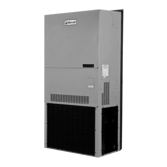
Model AVPA36
Manufactured By:
Marvair
Division of AIRXCEL
, Inc.
®
®
P.O. Box 400 • Cordele, Georgia 31010
156 Seedling Drive • Cordele, Georgia 31015
(229) 273-3636 • Fax (229) 273-5154
E-mail: marvairtech@airxcel.com • Internet: www.marvair.com
P/N 81025
4/2012 rev. 4
The most current version of this manual can be found at www.marvair.com.
Advertisement
Table of Contents
Troubleshooting

Related Manuals for Marvair AVPA36


Summary of Contents for Marvair AVPA36
- Page 1 P.O. Box 400 • Cordele, Georgia 31010 156 Seedling Drive • Cordele, Georgia 31015 (229) 273-3636 • Fax (229) 273-5154 E-mail: marvairtech@airxcel.com • Internet: www.marvair.com P/N 81025 4/2012 rev. 4 The most current version of this manual can be found at www.marvair.com.
- Page 2 How To Use This Manual This manual is intended to be a comprehensive guide to the installation of the Marvair Classic line of vertical ® packaged heat pumps. It contains installation, troubleshooting, maintenance, warranty, and application information. The information contained in this manual is to be used by the installer as a guide only. This manual does not supersede or circumvent any applicable national or local codes.
-
Page 3: Table Of Contents
WARNING • If the information in these instructions are not followed exactly, a fire may result causing property damage, personal injury or loss of life. • Read all instructions carefully prior to beginning the installation. Do not begin installation if you do not understand any of the instructions. •... - Page 4 Chapter 7 - Warranty Information 7.1 Standard Product Warranty ......................43 Exploded Views & Parts Lists ......................44 Appendix A - Installation Instructions of Field Installed Electric Heat ..........44 igures Figure 1 PC Control Board ......................14 Figure 2 Enthalpy Sensor Temperature Control Points ..............16 Figure 3 Fresh Air Hood Damper ....................22 Figure 4...
-
Page 5: General Description
Description and Specifications 1.1 General Description The Marvair® Classic Heat Pumps are high efficiency, vertical wall mounted heat pumps that provide heating, cooling and ventilation for a wide range of applications. Nominal cooling capacities range from 24,000 to 60,000 BTUH. The AVPA Series consists of units with EER's from 9.0 to 9.75. -
Page 6: Table 1A Cfm @ External Static Pressure - Avpa
A = 2011 1.2 Air Flow, Weights and Filter Sizes. Table 1a. Air Flow (Cubic Feet per Minute) AVPA External Static Pressure (WET COIL) MODEL 0.10 0.20 0.25 0.30 0.40 0.50 AVPA24 AVPA30 1100 1000 AVPA36 1310 1220 1185 1150 1060 AVPA42... -
Page 7: Table 2B Ship Weight - Hvpa & Hvpsa
MERV MODEL FILTER TYPE INCHES MILLIMETERS NUMBER UNIT RATING AVPA24 Return Air Filter 25 x 16 x 1 635 x 406 x 25 80135 AVPA30/36 & HVPA24 Return Air Filter 30 x 16 x 1 762 x 406 x 25... - Page 8 The use of the GreenWheel ERV reduces the energy load of the outside air. Exhausting stale, inside air keeps indoor pollutants and harmful gases to a minimum. The Marvair GreenWheel ERV has been tested and certified according to ARI Standard 1060.
- Page 9 latent energies between outgoing and incoming air streams in a cross flow arrangement. Except for two air movers, it has no moving parts. The media is impregnated with a RC134 polymeric desiccant that exchanges water by direct vapor transfer using molecular transport without the need of condensation.
- Page 10 while providing high pressure, loss of charge protection with an integral defrost function. Upon a call for mechanical cooling or heating, the controller will energize the compressor when a 24 VAC signal is applied to the “Y” terminal provided that all time delays and fault conditions are satisfied. It will energize the indoor blower when a 24 VAC signal is applied to the “G”...
-
Page 11: Defrost Mode
User Selectable Settings The control board has three potentiometers (pots) that allow the user to select settings to optimize the installation. See Figure 1 for location of the pots. Delay on Make The control has a pot settable 0.03 to10 minute delay on make timer that initiates upon initial power up only. -
Page 12: Test Mode
two options for the EHDD, “Yes” and “No”. If “Yes” is selected, the board will energize the EH terminals during a defrost cycle. If “No” is selected, the EH terminals will not be energized during a defrost cycle. The factory setting for EHDD is “No”. If the S-circuit is in the “Yes” position, the EHDD function will be disabled. - Page 13 the control will de-energize the compressor, register the first LPS fault, and initiate the 3 minute anti-short cycle timer. If two LPS faults occur within a one hour period, the control will enter a LPS lockout condition and energize the alarm contacts. The RED status LED will blink twice to indicate this condition.
-
Page 14: Options
HPS High Pressure switch terminals are the high pressure switch input. LPS Loss of Charge switch terminals are the loss of charge switch input. DS The DS terminals are the defrost sensor input. CS The CS terminals are the coil sensor (optional) input. This input will monitor the condenser coil temperature to allow the head pressure control to modulate the speed of the fan and maintain a constant head pressure. -
Page 15: Economizer
Factory installed. Available on all Classic units. Consult factory for details. Hot Gas Reheat (HGR) Marvair heat pumps equipped with the Hot Gas Reheat (HGR) allow the indoor humidity of the ®... -
Page 16: Figure 2 Enthalpy Sensor Temperature Control Points
Figure 2 - Enthalpy Sensor Temperature Control Points Mixed Air Sensor The mixed air sensor is a thermistor mounted on a bracket adjacent to the right side of the blower assembly. The thermistor senses the air temperature entering the structure, and provides a signal to the economizer controller for modulating the position of the damper. -
Page 17: Installation Requirements
Failure to observe and follow Warnings and Cautions and these Instructions could result in death, bodily injury or property damage. Read this manual and follow its instructions and adhere to all Cautions and Warnings in the manual and on the Marvair unit. -
Page 18: Table 4A Minimum Clearances - Avpa
Applications using duct work should be designed and installed in accordance with all applicable safety codes and standards. Marvair® strongly recommends referring to the current edition of the National Fire Protection Association Standards 90A and 90B before designing and installing duct work. -
Page 19: Installation Materials
8. Electrical Supply: The power supply must have the appropriate voltage, phase, and ampacity for the model selected. Voltage must be maintained above minimum specified values listed below. Refer to the unit data plate for ampacity requirements. Electrical Rating Designations* Nominal Voltage 208/230 208/230... - Page 20 30" x 16" Aluminum Return Grille for AVPA 42-48-60 and HVPA 30-36-42-49-60 Return Air Filter Grille 80672 28" x 14" Return Air Filter Grille. Required for use with the AVPA24/30/36 & HVPA24 units with the Greenwheel ERV Additional Items Needed: Additional hardware and miscellaneous supplies (not furnished by Marvair®) are needed for installation.
-
Page 21: Porting And Duct Work
General Information Note: The following instructions are for general guidance only. Due to the wide variety of installation possibilities, specific instructions will not be given.When in doubt, follow standard and accepted installation practices, or contact Marvair for additional assistance. ®... -
Page 22: Bracket Installation
2.5 Fresh Air Hood The fresh air hood is located on the inside, behind the slots on the bottom front panel. To access the hood, remove the screws that hold the front panel. The air flow can be adjusted from no (0%) fresh air to approximately 15% of rated air flow of fresh air, in 5% increments. -
Page 23: Mounting The Unit
For units with electric heat, a 1” clearance around the duct extensions is required. The duct extensions must be made of galvanized steel with a minimum thickness of .019” as per the NFPA standards 90A & 90B. Figure 4 - Classic Heat Pump Wall Mounting Detail 2.7 Mounting the Unit 1. -
Page 24: Electrical Connections
L2, & L3 for three phase models). CAUTION CAUTION! This system contains components that require phasing for correct rotation. Failure to observe rotation and correct on start-up will cause damage not covered by the Marvair Warranty. ® Classic Manual 4/2012 rev. 4... -
Page 25: Low Voltage Wiring
3. Scroll compressors, like several other types of compressors, will only compress in one rotational direction. The direction of rotation is not an issue with single-phase compressors since they will always start and run in the proper direction. However, three phase compressors will rotate in either direction depending upon phasing of power. -
Page 26: Figure 5A Humidity Control Wiring Detail
Thermostat Field Supplied Seven (7) Conductor, Color Coded 18 Gauge Thermostat Cable Humidity Controller Figure 5a - Humidity Control Wiring Detail - Heat Pumps Figure 5b - Thermostat Connection Diagram Classic Manual 4/2012 rev. 4... - Page 27 The spec sheets have detailed description of the various Marvair® thermostats. Since other thermostats or remote control systems may be used, the following procedures should be viewed as guidelines for standard thermostats with system and fan switches.
-
Page 28: Check-Out Of Heating Cycle
Once the indoor fan comes on, allow approximately three minutes for the compressor to start. Note that the outdoor fan may not come on immediately because it is cycled by refrigerant pressures Note: To check the system operation under different ambient conditions, the air temperature and enthalpy sensors must be "tricked". -
Page 29: Figure 6 Temperature Sensor Wires - Modulating Hgr Valve
(temperature). Marvair recommends 70ºF and no lower than 68ºF and no higher than 78ºF. Allow the refrigerant system to stabilize for at least five minutes and adjust the temperature as desired. -
Page 30: Ventilation System Set Up
3.4 Ventilation System Set-Up: Manual Fresh Air System (Configuration N). This is the standard ventilation system in the Classic heat pump. Fresh air ventilation by means of a damper can provide up to 15% of rated air flow of outside air. The damper has four positions corresponding to 0, 5, 10 and 15% of rated air flow of outside air. -
Page 31: Figure 9 Damper Air Path
at Various Static Pressures. This CFM is referred to as "C" in the illustration and equation below. Figure 9 - Damper Air Path b. "A" is the quantity of outside air expressed as a percentage of "C". For example, if the supply air is 1,220 CFM and 300 CFM of outside air is required, "A"... -
Page 32: Troubleshooting
A comprehensive understanding of the operation of the Classic Heat Pump is a prerequisite to troubleshooting. Please read the Chapter 1 for basic information about the unit. Marvair Classic Heat Pumps are thoroughly tested before they are shipped from the factory. Of ®... -
Page 33: Failure Symptoms Guide
The troubleshooting information in this manual is basic. The troubleshooting section contains problem / solution charts for general problems, followed by a compressor section. Not every problem can be anticipated. If you discover a problem that is not covered in this manual, we would be very grateful if you would bring it to the attention of our service department for incorporation in future revisions. -
Page 34: Compressor Troubleshooting
5. Reset the lock out relay at the thermostat. 4.3 Compressor Troubleshooting Obtain the heat pump's model number and serial number, the compressor's model number and contact Marvair for compressor specifications. ® It is important to rule out other component failures before condemning the compressor. -
Page 35: Electric Heat Control
2. Running Amperage: Connect a clip-on type ammeter to the (common) lead to the compressor. Turn on the supply voltage and energize the unit. The compressor will initially draw high amperage; it should soon drop to the RLA value or less. If the amperage stays high, check the motor winding resistances. -
Page 36: Chapter 5 - Electrical Schematics 5.1 Electrical Schematics
to the heater contactor(s) which powers all the heating elements. This single function thermal cut-out switch operates totally independent of the dual thermal cut-out switch described above. If the single function switch senses an overheat situation, it opens the control circuit and turns off all of the installed heating elements via the heater contactor(s). -
Page 37: Figure 11A Typical 1Ø Electrical Schematic Diagram Classic Heat Pump (Models Avpa) With Manual Outside Air Damper
Figure 11a - Typical 1ø Electrical Schematic Diagram Classic Heat Pump (Models AVPA) with Manual Outside Air Damper Classic Manual 4/2012 rev. 4... -
Page 38: Figure 11B Typical 208/230V. 3Ø Electrical Schematic Diagram
Figure 11b - Typical 208/230v. 3ø Electrical Schematic Diagram Classic Heat Pump (Models AVPA) Classic Manual 4/2012 rev. 4... -
Page 39: Figure 11C, Typical 460V. 3Ø Electrical Schematic Diagram Classic Heat Pumps, Models Avpa, With The Pc Control Board
Figure 11c, Typical 460v. 3ø Electrical Schematic Diagram Classic Heat Pumps, Models AVPA, with the PC Control Board Classic Manual 4/2012 rev. 4... -
Page 40: Figure 11D - Typical Electrical Schematic Diagram Classic Heat Pump (Models Hvpa) With Manual Outside Air Damper
LOSS OF CHARGE Figure 11d - Typical Electrical Schematic Diagram Classic Heat Pump (Models HVPA) with Manual Outside Air Damper Classic Manual 4/2012 rev. 4... -
Page 41: Classic Heat Pump (Models Hvp) With Economizer
Figure 11e - Typical Electrical Schematic Diagram Classic Heat Pump (Models HVPA) with Economizer Classic Manual 4/2012 rev. 4... -
Page 42: Scheduled Maintenance
Maintenance 6.1 Scheduled Maintenance Marvair strongly recommends that the heat pump be serviced a minimum of twice a year – once ® prior to the heating season and once prior to the cooling season. At this time the filters, evaporator coil, condenser coil, the cabinet, and condensate drains should be serviced as described below. -
Page 43: Chapter 7 - Warranty Information 7.1 Standard Product Warranty
Marvair will honor its warranty and furnish the required replacement part. All costs for shipment and risk of loss during shipment of the product to Marvair and back to the owner shall be the responsibility and liability of the owner. Upon written request by an owner, Marvair may... -
Page 44: Exploded Views & Parts Lists
The 1" (25.4 mm) clearance must extend on all sides of the supply duct for the first 3 feet (1 meter) from the unit. IMPORTANT: Marvair requires a minimum of 1" (25.4 mm) from the surface of any supply ducts to combustible material for the first 3 feet (1 meter) of the duct. - Page 45 first 3 feet (1 meter). Ductwork must be firmly attached, secured and sealed to prevent air leakage. Do not use duct liner on inside of supply duct within 4 feet (122 cm) of the unit. Galvanized metal duct extensions should be used to simplify connections to duct work and grilles. Use fabric boots to prevent the transmission of vibration through the duct system.
- Page 46 Classic Manual 4/2012 rev. 4...
Need help?
Do you have a question about the AVPA36 and is the answer not in the manual?
Questions and answers