Table of Contents
Advertisement
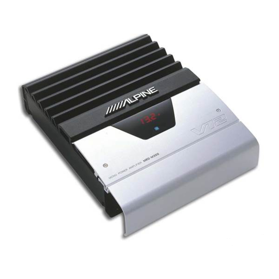
MRD-M500/MRD-M300
• OWNER'S MANUAL
• MODE D'EMPLOI
• MANUAL DE OPERACIÓN
CONTENTS
ACCESSORIES ....................................................... 1
Introduction ........................................................... 2
WARNING .............................................................. 2
CAUTION ............................................................... 3
INSTALLATION ...................................................... 4
CONNECTIONS ...................................................... 6
OPERATION METHOD ......................................... 11
IN CASE OF DIFFICULTY ...................................... 18
SYSTEMS ............................................................ 19
SPECIFICATIONS ................................................. 20
ACCESSORIES
• End Cover ........................................................... 1
• Terminal Cover ................................................... 1
• Bracket ............................................................... 2
• Hexagon Wrench ................................................ 1
• Self-Tapping Screw ............................................ 4
• Machine Screw ................................................... 4
• Hexagon Screw .................................................. 2
• Double Face Tape ........................................ 1 SET
• Cushion ....................................................... 1 SET
• Insulation Tube (for Power Supply) .................... 1
• Insulation Tube (for Speaker Output) ................. 1
• Speaker Input Connector (MRD-M300 Only) ........... 1
English
MONO POWER AMPLIFIER
Please read this manual to maximize your enjoyment of the outstanding
performance and feature capabilities of the equipment, then retain the
manual for future reference.
Veuillez lire ce mode d'emploi pour tirer pleinement profit des excellen-
tes performances et fonctions de cet appareil, et conservez-le pour toute
référence future.
Lea este manual, por favor, para disfrutar al máximo de las excepciona-
les prestaciones y posibilidades funcionales que ofrece el equipo, luego
guarde el manual para usarlo como referencia en el futuro.
English
TABLE DES MATIERES
ACCESSOIRES ........................................................... 1
Introduction ............................................................... 2
AVERTISSEMENT ...................................................... 2
ATTENTION ................................................................ 3
INSTALLATION .......................................................... 4
CONNEXIONS ............................................................ 6
METHODE DE FONCTIONNEMENT .......................... 11
EN CAS DE PROBLEME ............................................ 18
SYSTEMES ............................................................... 19
SPECIFICATIONS ..................................................... 20
• Couvercle d'achèvement ........................................ 1
• Couvercle cache-bornes ........................................ 1
• Support ................................................................. 2
• Clé hexagonale ...................................................... 1
• Vis autotaraudeuse ................................................ 4
• Vis à métaux .......................................................... 4
• Vis à six pans ........................................................ 2
• Ruban adhésif double face ............................. 1 JEU
• Coussin .......................................................... 1 JEU
• Tube d'isolation (pour alimentation) ...................... 1
• Tube d'isolation (pour la sortie de haut-parleur) ..... 1
• Connecteur d'entrée de haut-parleur
(MRD-M300 uniquement) ........................................ 1
Français
Français
ACCESSOIRES
ÍNDICE
ACCESORIOS ........................................................ 1
Introducción .......................................................... 2
ADVERTENCIA ....................................................... 2
PRUDENCIA .......................................................... 3
INSTALACIÓN ........................................................ 4
CONEXIONES ........................................................ 6
MÉTODO DE OPERACIÓN .................................... 11
EN CASO DE DIFICULTAD ....................................... 18
SISTEMAS ............................................................ 19
ESPECIFICACIONES ............................................ 20
ACCESORIOS
• Cubierta de acabado ........................................... 1
• Cubierta de terminales ....................................... 1
• Soporte .............................................................. 2
• Llave hexagonal .................................................. 1
• Tornillo autorroscante ........................................ 4
• Tornillo para metales .......................................... 4
• Tornillo hexagonal .............................................. 2
• Cinta de doble cara ................................. 1 JUEGO
• Almohadilla ............................................ 1 JUEGO
• Tubo de aislamiento (para la alimentación) ........ 1
• Tubo de aislamiento (para la salida de altavoz) .. 1
• Conector de entrada del altavoz
(MRD-M300 solamente) ....................................... 1
Español
R
Español
1
Advertisement
Table of Contents

Summarization of Contents
Introduction and Safety Precautions
Understanding Your Owner's Manual
Read this manual to maximize enjoyment and retain for future reference.
Critical Safety Precautions
Crucial warnings and cautions to prevent injury, damage, or fire.
Installation Guide
Amplifier Mounting Steps
Steps for marking, drilling, and securing the amplifier to the vehicle chassis.
End Cover Installation
Instructions for attaching decorative end covers to improve product appearance.
Terminal Cover Mounting
Procedure for mounting the terminal cover securely after connections are made.
Audio and Power Connections
Speaker and RCA Connections
Connecting speakers to the unit and RCA cables from the head unit.
Power, Remote, and Ground Wiring
Connecting the battery, remote turn-on lead, and ground lead for proper operation.
Wire Lead Connection Precautions
Precautions for connecting wire leads, including size, insulation, and security.
Operating Your Amplifier
Display, Buttons, and Indicators
Overview of display functions, buttons, and indicators for operation.
Mode 1: Input Mode Setup
Selecting Input Mode
Choosing between 1-channel or 2-channel input for optimal signal matching.
Adjusting Input Level
Setting the head unit volume to prevent distortion and match amplifier input.
Mode 2: Low Pass Filter Setup
Turning Low Pass Filter On/Off
Enabling or disabling the low pass filter to remove unwanted high frequencies.
Adjusting Low Pass Filter Frequency
Setting the crossover frequency for optimal subwoofer integration.
Mode 3: Subsonic Filter Setup
Turning Subsonic Filter On/Off
Enabling or disabling the subsonic filter to minimize low-frequency distortion.
Adjusting Subsonic Filter Frequency
Setting the subsonic filter frequency to control very low frequencies.
Mode 4: Parametric Equalizer Setup
Turning Parametric Equalizer On/Off
Enabling or disabling the parametric equalizer for sound tuning.
Adjusting Parametric EQ Frequency
Setting the center frequency for the parametric equalizer band.
Adjusting Parametric EQ Width
Adjusting the bandwidth (Q value) of the parametric equalizer.
Adjusting Parametric EQ Level
Adjusting the gain or cut level for the parametric equalizer band.
Mode 5: Bass Compensation Setup
Turning Bass Compensation On/Off
Enabling or disabling the bass compensation feature for enhanced bass definition.
Mode 6: Time Correction Setup
Turning Time Correction On/Off
Enabling or disabling the digital time correction feature.
Adjusting Time Correction Delay
Setting the delay time for speaker signals to align properly.
Mode 7: Phase Setup
Selecting Phase (0°/180°)
Flipping subwoofer polarity to prevent phase cancellation and improve bass.
Mode 8: Amplifier ID and Turn On Delay
Selecting Amplifier ID
Assigning a unique ID to each amplifier for controller recognition.
Setting Turn On Delay
Adjusting turn-on delay to prevent inrush current or turn-on "pop".
Mode 9: Safe Mode and Mode 0: Memory Settings
Turning Safe Mode On/Off
Disabling output stage for safe adjustments, preventing speaker damage.
Memory Write and Read Modes
Storing and recalling amplifier settings for easy recall and backup.
Troubleshooting Common Issues
Common Amplifier Problem Diagnosis
Identifying problems like low volume, no sound, or indicator errors.
Resolving Amplifier Indicator Errors
Understanding and resolving specific error codes displayed by the amplifier.
System Configurations and Specifications
System Wiring Diagrams Overview
Visual guides for single-speaker and parallel-speaker system configurations.
Detailed Technical Specifications
Detailed technical data including power output, frequency response, and impedance.
Service and Support
Customer Service and Warranty Information
Contact information for warranty inquiries and support for customers.


Need help?
Do you have a question about the MRD-M300 and is the answer not in the manual?
Questions and answers