Table of Contents
Advertisement
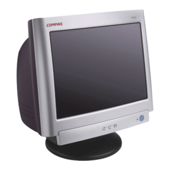
COLOR MONITOR
SERVICE MANUAL
CHASSIS NO. : CA-110
FACTORY MODEL: CQ771G
MODEL: S7500 (PE1165T), S7500 (PE1165),
MV7500 (PE1165U), MV7500 (PE1165),
CV7500 (PE1165U)
*(
) ID LABEL Model No.
CAUTION
BEFORE SERVICING THE UNIT,
READ THE SAFETY PRECAUTIONS IN THIS MANUAL.
Website:http://biz.LGservice.com
E-mail:http://www.LGEservice.com/techsup.html
Advertisement
Table of Contents

Summarization of Contents
Safety Precautions
Component Safety Warnings
Highlights safety-related components, risks of non-specified parts, and circuit modification cautions.
High Voltage and Electrical Hazards
Covers safety checks for high voltage, fire/shock hazards, and using appropriate tools.
X-Radiation and Implosion Protection
Details X-radiation prevention and the implosion protection system for CRT tubes.
Operating Instructions
Monitor Views and Control Panel Operation
Illustrates monitor views and details front control panel functions, including hot keys.
Block Diagram Descriptions
Line Filter and Noise Suppression
Suppresses power line noise and prevents interference with other appliances.
Degauss Circuit Functionality
Eliminates screen color impurities by degaussing the shadow mask during power-on.
SMPS Operation Details
Details the SMPS operation from AC input to secondary voltage generation.
X-Ray Protection Mechanism
Describes how the MICOM monitors high voltage and stops deflection to prevent X-radiation.
Further Block Diagram Descriptions
Blanking, Brightness, and Rotation Circuits
Covers H&V blanking, brightness control, and image rotation (tilt) circuit functions.
OSD and Video Signal Processing
Explains the OSD circuit and the video pre-amp/output circuits for signal handling.
Adjustment Procedures
General Adjustment Guidelines
Provides guidelines for adjustment procedures, including required tools and warming up the monitor.
Degaussing and Factory Mode Setup
Covers degaussing procedures and detailed steps for factory mode adjustments like voltage and synchronization.
White Balance and Luminance Calibration
Describes the process for adjusting white balance and luminance using specific patterns and meters.
Additional Adjustment Procedures
Input EDID Data Configuration
Details the procedure for inputting EDID data, including saving it after power cycle.
Focus Adjustment Method
Describes the steps for adjusting the monitor's focus using specific patterns on the screen.
Troubleshooting Guide
No Power Diagnostics
A flowchart to diagnose and identify faults causing the monitor to not power on.
No Character Troubleshooting
Offers a flowchart to diagnose issues when the screen displays no characters or video signal.
No Raster Troubleshooting
Presents a flowchart for troubleshooting scenarios where no raster is displayed on the screen.
No Horizontal Deflection
Provides a flowchart to diagnose and identify faults causing the absence of horizontal deflection.
Horizontal Linearity Issues
Troubleshooting H-Linearity Problems
Guides users through diagnosing issues related to horizontal linearity, including checking components and signal tables.
No Vertical Deflection
Diagnosing Vertical Deflection Absence
Offers a flowchart to diagnose and identify faults causing the absence of vertical deflection.
OSD Troubleshooting
Diagnosing On-Screen Display Faults
Provides a flowchart to diagnose issues with the On-Screen Display, checking ICs and waveforms.
DPM Troubleshooting
Display Power Management Issues
Guides troubleshooting for Display Power Management failures, checking signals and modes.
No Degaussing Troubleshooting
Degaussing Functionality Issues
Provides a flowchart to diagnose issues related to the degaussing function, checking ICs, transistors, and coils.
Tilt/Rotation Troubleshooting
Diagnosing Tilt/Rotation Functionality
Offers a flowchart to diagnose problems with the tilt or rotation function, checking ICs, lines, and transistors.
Pin Configuration
TDA4866J Pin Configuration
Details the pin assignments and functions for the TDA4866J vertical deflection booster IC.
M24C08 EEPROM Pinout
Shows the pin configuration and logic diagram for the M24C08 serial I2C bus EEPROM.
LM2469 CRT Driver Connection
Provides the connection diagram and pinout for the LM2469 monolithic triple 9nS high gain CRT driver.
TDA4857 Pin Configuration
TDA4857 Pin Configuration and Functions
Details the pin assignments, symbols, and descriptions for the TDA4857 Autosync Deflection Controller.


Need help?
Do you have a question about the MV7500 and is the answer not in the manual?
Questions and answers