
Related Manuals for Omron SYSMAC CJ2


Summarization of Contents
Introduction
Intended Audience
Details the target personnel for this manual, requiring knowledge of electrical systems.
Applicable Products
Lists the CJ-series CJ2 CPU Units covered by this manual, including specific models.
Section 1 Overview
1-1 Overview of CJ2 CPU Units
Provides a general overview of the multi-functional features of SYSMAC CJ2-series CPU Units.
1-2 Basic Operating Procedure
Outlines the general procedure for setting up, wiring, connecting, and operating the CJ2 PLC.
1-3 Specifications
Details the general, performance, and function specifications for CJ2 CPU Units.
Section 2 Basic System Configuration and Devices
2-1 Basic System Configuration
Describes the basic system configuration consisting of CPU Rack and Expansion Racks.
2-2 Expanded System Configuration
Explains system configurations connected via the CPU Unit's serial port and Communications Units.
Section 3 Nomenclature and Functions
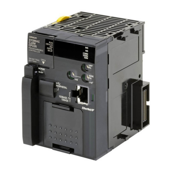
3-1 CPU Units
Details the components and functions of CJ2 CPU Units, including sections and indicators.
3-2 Memory Card
Covers models, specifications, operating procedures, and installation/removal of memory cards.
3-3 Pulse I/O Modules (CJ2M CPU Unit Only)
Describes models, specifications, and part names/functions of Pulse I/O Modules for CJ2M.
3-4 Serial Option Boards (CJ2M-CPU3@ Only)
Provides an overview of serial option boards that can be used with the CJ2M-CPU3@.
3-5 Power Supply Units
Details models, specifications, components, and selection criteria for power supply units.
3-6 CJ-series Basic I/O Units
Explains basic I/O units with terminal blocks and those with connectors, including part names.
3-7 I/O Control Units and I/O Interface Units
Describes the component names and system configuration for I/O control and interface units.
Section 4 Support Software
4-1 Support Software
Introduces support software applications for programming and debugging OMRON PLCs.
4-2 Connection Methods
Details connection methods for linking the PLC to a personal computer via USB, RS-232C, or Ethernet.
Section 5 Installation
5-1 Fail-safe Circuits
Explains safety circuits to prevent dangerous conditions during PLC errors or power supply issues.
5-2 Installation
Covers installation and wiring precautions, control panel installation, and component connection.
5-3 Wiring
Provides detailed instructions for wiring power supply units, I/O units, and Ethernet cables.
5-4 Control Panel Installation
Details environmental considerations for control panel installation, including temperature and electrical factors.
Section 6 Troubleshooting
6-1 CPU Unit Errors
Describes procedures for checking and handling errors related to the CPU Unit itself.
6-2 Troubleshooting Built-in EtherNet/IP Port Errors
Provides methods for checking and troubleshooting errors specific to the built-in EtherNet/IP port.
6-3 Non-CPU Unit Errors and Remedies
Details error causes and remedies for units other than the CPU Unit, such as I/O units.
Section 7 Inspection and Maintenance
7-1 Inspections
Outlines daily or periodic inspections required to maintain peak PLC operating condition.
7-2 Replacing the Battery
Describes the purpose of the battery, its service life, and the procedure for replacement.
7-3 Power Supply Unit Replacement Time
Explains the principle of replacement notification and the timing for replacing power supply units.
Section 8 Backup Operations
8-1 Backing Up Data
Describes the two methods available for backing up PLC data: using a computer or front-panel switches.
8-2 Using a Computer to Back Up Data
Details the PLC Backup Tool for backing up, comparing, and restoring data from the PLC.
8-3 Simple Backup
Explains the simple backup operation using DIP switch settings and the Memory Card Power Switch.
Section A Appendices
A-1 Specifications of Basic I/O Units
Provides specifications for various basic I/O units, including input and output modules.
A-2 Dimensions
Contains detailed dimensional drawings for CPU Units, power supply units, and I/O units.
A-3 Fatal and Non-fatal Error Details
Describes detailed information on fatal and non-fatal errors that can occur in the CPU Unit.
A-4 Connecting to a Serial Port on the CPU Unit
Provides configurations and wiring methods for connecting to serial ports on CPU Units.
A-5 Installing the USB Driver
Details the procedure for installing the USB driver for connecting the PLC to a computer.
A-6 Load Short-circuit Protection and Line Disconnection Detection for Basic I/O Units
Explains load short-circuit protection and line disconnection detection for basic I/O units.
A-7 Relay Output Noise Reduction Methods
Provides methods for reducing noise generated by relay output switching.
A-8 Functions Supported for Unit Versions
Details functions supported by different unit versions of CJ2 CPU Units and CX-Programmer.
Need help?
Do you have a question about the SYSMAC CJ2 and is the answer not in the manual?
Questions and answers