
Related Manuals for McIntosh XLS360


Summary of Contents for McIntosh XLS360
- Page 1 Loudspeaker Systems XLS360 XLS340 XLS320 XCS350 Owner’s Manual McIntosh Laboratory, Inc. 2 Chambers Street Binghamton, New York 13903-2699 Phone: 607-723-3512 FAX: 607-724-0549...
-
Page 2: Important Safety Instructions
WARNING - TO REDUCE RISK OF FIRE OR ELECTRICAL SHOCK, DO NOT EXPOSE THIS EQUIPMENT TO RAIN OR MOISTURE. IMPORTANT SAFETY INSTRUCTIONS! PLEASE READ THEM BEFORE OPERATING THIS EQUIPMENT. 1. Read these instructions. 2. Keep these instructions. 3. Heed all warnings. 4. -
Page 3: Table Of Contents
Phone: 607-723-1545 Fax: 607-772-3308 Customer Service If it is determined that your McIntosh product is in need of repair, you can return it to your Dealer. You can also return it to the McIntosh Laboratory Service Department. For as- sistance on factory repair return procedure, contact the McIntosh Service Department at: McIntosh Laboratory, Inc. -
Page 4: Important Information
To reproduce it accurately, all forms of distortion, both harmonic and intermodulation, must be kept to a minimum. This has been the result of the design of the new McIntosh XLS320, XLS340, XLS360 and XCS350 Loudspeaker Systems. Each loudspeaker element and crossover compo- nent has been carefully designed for low distortion, dura- bility and efficiency. -
Page 5: Performance Features
Center Channel or Right Channel for use in a multi- channel system. • Shielded Magnetic Field The XLS320, XLS340, XLS360 and XCS350 may be used in Home Theater Installations near a television receiver or monitor without causing the television image to degrade. McIntosh has designed special shielding around the magnetic structure of the XLS320, XLS340, XLS360 and XCS350 Loudspeaker Elements to prevent interference. -
Page 6: Dimensions
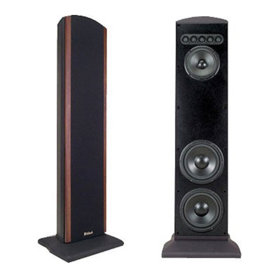
Dimensions The following dimensions can assist in determining the best location for the XLS320 or XLS340 Loudspeaker Sys- tem. There is additional information on page 18 pertaining to installing the Loudspeaker. Front View of XLS320 with Grille Removed Rear View of XLS320 Side View of XLS320 -5/8"... - Page 7 Front View of XLS340 with Grille Removed " -3/8 100.0cm " -9/16 87.8cm " -3/16 38.6cm " -13/16 5.8cm " -3/8 18.7cm Note: The XLS340 is supplied with optional adjustable feet, four Tiptoes and four Glides. If they are used with the XLS340 please allow for the added height.
- Page 8 Dimensions, con’t The following dimensions can assist in determining the best location for the XLS360 or XCS350 Loudspeaker Sys- tem. There is additional information on page 18 pertaining to installing the Loudspeaker. Front View of XLS360 with Grille Removed "...
- Page 9 Note: The XCS350 is supplied with an adjustable Stabilizer Bar. Please allow for various height/angle. Front View of XCS350 with Grille Removed -9/16 16.7cm -1/32 43.3cm -1/2 69.9cm 24.3cm Rear View of XCS350 with the stabilizer bar removed Top View of XCS350 "...
-
Page 10: Xls320
The instructions that follow are for the unpacking, assem- bly and setup of the XLS320, XLS340, XLS360 and XCS350 Loudspeaker Systems as supplied. For several models, an optional In Wall Mounting Kit is available. If the Loudspeaker is to be Mounted On or In Wall, refer to “Locating the Loudspeaker System”... -
Page 11: Unpacking The Xls360
6. Place the Loudspeaker System, with the front facing up, on foam end caps located on top of the shipping carton, with the bottom of the XLS340 overhanging the end of the shipping carton. Refer to figure 3. Bottom of XLS340 Foam end caps with the flat surface Figure 3... -
Page 12: Unpacking The Xcs350
6. Place the Loudspeaker System, with the Rubber Bumpers Tiptoes Glides Notes: 1. When the XCS350 is to be used with the supplied Stabilizer Bar and Hardware, proceed to step 6. 2. The XCS350 Loudspeaker is also supplied with On Wall Mounting Brackets and Hardware. - Page 13 7. Attach the four rubber bumpers to the bottom long edge of the XCS350 Loudspeaker System. Refer to fig- ure 8. 8. Loosen, but do not remove, the three screws securing the Stabilizer Bar to the back of the XCS350. Refer to figure 9. Stabilizer Bar Screws Stabilizer Bar Figure 9 9.
- Page 14 Installation, con’t 2. Attach either the flush mount or angle mount bracket to the rear of the Loudspeaker using the two screws (just removed in the previous step), being sure to orient the bracket as illustrated in figures 15 and 16. 3.
- Page 15 Note: Use extreme caution to avoid any existing electrical wiring, plumbing, etc., located inside the wall. 4. Refer to figures 23 and 24 to in- stall the appropriate Wall Brack- ets on the wall (orient the bracket as illustrated) using the supplied Mounting Screws.
- Page 16 Installation, con’t How to Mount the XCS350 Loudspeaker On the Wall The supplied On Wall Mounting Brackets allow for four different mounting positions of the XCS350 Loudspeaker relative to the wall, both vertical and horizontial. Two posi- tions are flush mount, with the Loudspeaker close to and parallel with the wall.
- Page 17 Installation, con’t 6. Align the Grille fasteners to the Loudspeaker Grom- mets (four on each side). Carefully push down to se- cure the Grille to the Loudspeaker. Figure 33 Figure 31 Figure 34 Figure 32...
-
Page 18: Locating The Loudspeaker
Locating the Loudspeaker System Loudspeaker placement in a room can greatly affect performance. The XLS320, XLS340, XLS360 and XCS350 are designed for use as a Left and Right Loudspeaker in a Music System, or as a Front and Surround Loudspeakers in a Home Theater System. -
Page 19: Tweeter Array Optimization
Tweeter Array Optimization The XLS320, XLS340, XLS360 and XCS350 Loudspeaker Systems incorporate a special feature in the Crossover Network for optimization of the sound coming from the five tweeter array, refer to figure 37. The three different settings in the... - Page 20 Connection for use with a Low Power Amplifier (default setting) Preparing Hookup Cables The McIntosh Loudspeaker Systems utilize binding posts for speaker wire connections. Prepare the Loudspeaker Hookup Cables that attach to the Power Amplifier Output Terminals: Bare wire cable ends: Carefully remove sufficient insulation from the cable ends, refer to figures 43, 44 and 45.
- Page 21 Posts. Note: The Low Frequency Response of a XLS320 Loudspeaker may be extended with the addition of a Powered Subwoofer like the McIntosh XLS112 to the Music/Home Theater System. 4. Connect the remaining Loudspeaker(s) and Amplifier Channel(s) in the same manner.
- Page 22 Connection with one Amplifier Preparing Hookup Cables The McIntosh Loudspeaker Systems utilize binding posts for speaker wire connections. Prepare the Loudspeaker Hookup Cables that attach to the Power Amplifier Output Terminals: Bare wire cable ends: Carefully remove sufficient insulation from the cable...
- Page 23 Amplifier Number One to the Loudspeaker WOOFER McIntosh Two Channel Power Amplifier Number One How to Connect the XLS340, XLS360 and XCS350 Loudspeakers NEGATIVE (-) Binding Post. 3. Connect a Loudspeaker cable from the 8S (OHM) or Positive (+) Binding Post of the same Channel of Am- plifier Number One to the Loudspeaker WOOFER POSITIVE (+) Binding Post.
-
Page 24: Xls320
Black knit fabric with wood trim strips finished in Champagne Gold Optional Wood Trim Finishes Natural Cherry, Red Cherry or Black Ash (Check with your McIntosh Dealer for Additional Details) Weight (each) 24 pounds (10.9kg) net, 27 pounds (12.2kg) in shipping carton... -
Page 25: Xcs350
Black knit fabric with wood trim strips finished in Champagne Gold Optional Wood Trim Finishes Natural Cherry, Red Cherry or Black Ash (Check with your McIntosh Dealer for Additional Details) Weight (each) 107 pounds (48.5kg) net, 120 pounds (54.4kg) in shipping carton... -
Page 26: Packing Instructions
Use the original shipping carton and parts only if they are in good serviceable condition. If a shipping carton or any of the interior part(s) are needed, please call or write Customer Service Department of McIntosh Laboratory. Please see the Parts List for the correct part numbers. Quantity... -
Page 27: Xls360
XLS360 Shipping Cartons and Parts List XCS350 Shipping Carton and Parts List Packing Instructions Quantity Part Number Description 034290 Shipping carton top 034289 Shipping carton bottom 034244 Foam end caps 034245 Foam center cap 034309 Floor stand shipping carton 033300... - Page 28 McIntosh Laboratory, Inc. 2 Chambers Street Binghamton, NY 13903 The continuous improvement of its products is the policy of McIntosh Laboratory Incorporated who reserve the right to improve design without notice. Printed in the U.S.A. McIntosh Part No. 04094100...
Need help?
Do you have a question about the XLS360 and is the answer not in the manual?
Questions and answers