Advertisement
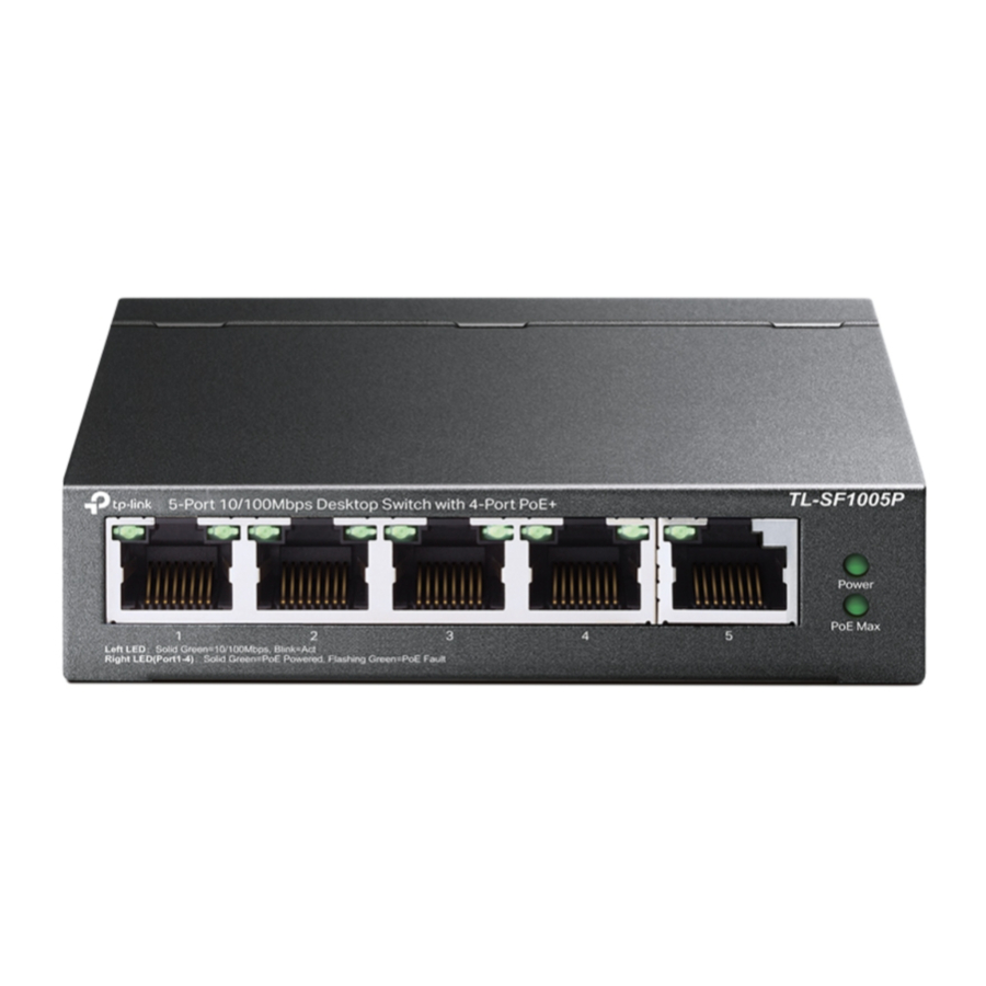
LED Explanation
Power
 Power | On: Power on Off: Power off |
PoE MAX
PoE Max | TL-SF1005LP On: 34 W≤Total power supply < 41 W Flashing: Total power supply ≥ 41 W Off: Total power supply < 34 W |
| TL-SF1005P On: 60 W≤Total power supply < 67 W Flashing: Total power supply ≥ 67 W Off: Total power supply < 60 W |
Link/Act and PoE Status

Switch Explanation
Priority (Port 1–2)

Off: All the ports transmit data in the same priority.
On: Port 1 and 2 transmit data in a higher priority than other ports. When congestion occurs, packets which are transmitted by the ports with higher priority occupy the whole bandwidth.
Extend (Port 1–4)

Off: Port 1–4 run at 10/100 Mbps and support PoE power supply up to 100 m away.
On: Port 1–4 run at 10 Mbps and support PoE power supply up to 250 m away.
 Note: For simplicity, we will take TL-SF1005P for example throughout the Guide.
Connection

Note:
- PoE ports can also connect to non-PoE devices, but only transmit data.
- TL-SF1005LP can supply up to 15.4 W for each PoE port and 41 W for all PoE ports.
- TL-SF1005P can supply up to 30 W for each PoE port and 67 W for all PoE ports.
Frequently Asked Questions (FAQ)
Q1. Why is the Power LED not lit?
The Power LED should be lit when the power system is working normally. If the Power LED is not lit, please try the following:
A1: Make sure the AC power cord is connected to the switch with power source properly.
A2: Make sure the voltage of the power supply meets the requirements of the input voltage of the switch.
A3: Make sure the power source is ON.
Q2. Why is the Link/Act LED not lit while a device is connected to the corresponding port?
It is recommended that you check the following items:
A1: Make sure that the cable connectors are firmly plugged into the switch and the device.
A2: Make sure the connected device is turned on and works normally.
A3: The cable must be less than 100 meters long (328 feet). If Extend Mode is enabled, it should be less than 250 meters (820 feet).
Q3. Why are PoE ports not supplying power for PoE devices?
When the total power consumption of connected PoE devices exceeds the maximum, the PoE port with a smaller port number has higher priority. The system will cut off power to the ports with larger port numbers to ensure supplying to other ports.
Take TL-SF1005P as an example. If port 1, 2 and 4 are consuming 15.4 W respectively, and an additional PoE device with 21 W is connected to port 3, the system will cut off the power of port 4 to compensate for the overload.
Specifications
General Specifications
| Standard | IEEE 802.3i, IEEE 802.3u, IEEE 802.3x, IEEE 802.3af, IEEE802.1p IEEE 802.3at (Only for TL-SF1005P) |
| Protocol | CSMA/CD |
| Interface | 10/100 Mbps RJ45 Ports, Auto-Negotiation MDI/MDIX PoE Ports: Port 1-Port 4 Total Power Supply: W (for TL-SF1005LP)/67 W (for TL-SF1005P) |
| Network Media (Cable) | 10BASE-T: UTP category 3, 4, 5 cable (maximum 100 m); EIA/TIA-568 100Ω STP (maximum 100 m) 100BASE-TX: UTP category 5, 5e cable (maximum 100 m); EIA/TIA-568 100Ω STP (maximum 100 m) |
| Switching Capacity | Gbps |
| MAC Address Table | 2K |
| Transfer Method | Store-and-Forward |
| MAC Address Learning | Automatically learning, automatically aging |
| Power Supply | External Power Adapter Input: Output: |
| Wall Mountable | Yes |
| Distance Between Mounting Holes | 39 mm |
Environmental and Physical Specifications
| Operating Temperature | 0˚C to 40˚C (32˚F to 104˚F) |
| Storage Temperature | -40˚C to 70˚C (-40˚F to 158˚F) |
| Operating Humidity | 10% to 90%RH non-condensing |
| Storage Humidity | 5% to 90%RH non-condensing |
Support
To ask questions, find answers, and communicate with TP-Link users or engineers, please visit https://community.tp-link.com to join TP-Link Community.
For technical support and other information, please visit https://www.tp-link.com/support, or simply scan the QR code.

If you have any suggestions or needs on the product guides, welcome to email techwriter@tp-link.com.cn.
Safety Information
- Keep the device away from water, fire, humidity or hot environments.
- Do not attempt to disassemble, repair, or modify the device. If you need service, please contact us.
- Do not use damaged charger or USB cable to charge the device.
- Do not use any other chargers than those recommended.
- Adapter shall be installed near the equipment and shall be easily accessible.
- Use only power supplies which are provided by manufacturer and in the origin packing of this product. If you have any questions, please don't hesitate to contact us.
Documents / Resources
References
Download manual
Here you can download full pdf version of manual, it may contain additional safety instructions, warranty information, FCC rules, etc.
Advertisement


Need help?
Do you have a question about the TL-SF1005P and is the answer not in the manual?
Questions and answers