Advertisement
- 1 OVERVIEW
- 2 PRESET PAGE (GRAPHIC VIEW)
- 3 EDITING (EDIT PAGE IN GRAPHIC VIEW)
- 4 SAVING (SAVE AS PAGE IN GRAPHIC VIEW)
- 5 FAVORITES BANK
- 6 MODIFIERS
- 7 EXPRESSION
- 8 LOOPER
- 9 DELAY STRUCTURES
- 10 CATEGORIES AND ELEMENTS
- 11 MIDI CC TABLE
- 12 MIDI PC TABLE
- 13 TUNER
- 14 GLOBALS
- 15 TEXT VIEW (ALTERNATIVE VIEW OF EDIT PAGE)
- 16 EXPORTING PRESETS
- 17 FACTORY RESET
- 18 FIRMWARE UPDATE
- 19 GLOSSARY
- 20 TECHNICAL SPECIFICATIONS
- 21 Documents / Resources
OVERVIEW
LVX
LVX is a Modular Delay System which breaks the paradigm of pre-set delay types in favor of freedom and flexibility. The architecture of LVX allows ultimate creative freedom to design a custom delay, exactly as you've dreamed of. We designed a completely new UI and experience from the ground up, to make a complex system immediately intuitive to navigate. LVX is built of discrete processing elements and control signal generators that we call Modifiers. They can be connected as desired for nearly infinite flexibility in crafting custom sounds. Experiencing the built in factory presets will demonstrate a variety of examples of the power within LVX. The true creative potential of LVX will be revealed as you discover all of the new ways to unveil your own vision.
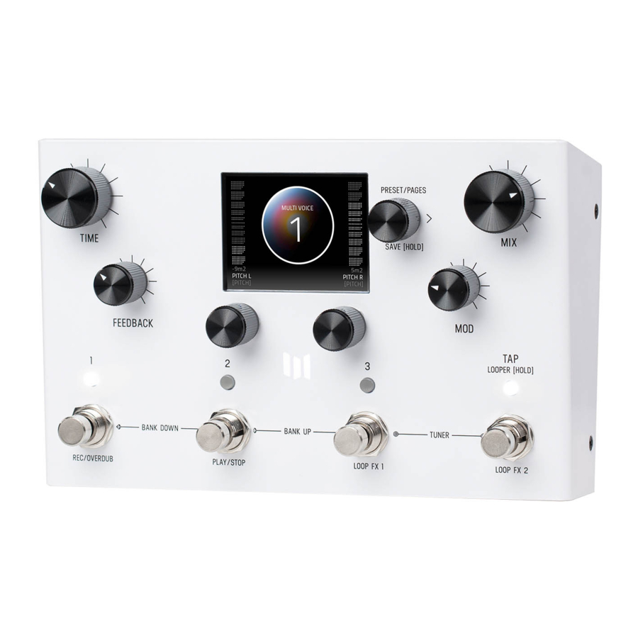
3 MAIN CONTROLLERS: C1, C2, C3
When using LVX, 3 knobs are your main navigation controllers: C1, C2, C3.
The other four knobs are your top level controls for TIME, FEEDBACK, MOD, and MIX.

7 HIGHLIGHTED FEATURES

BACK PANEL CONNECTIONS

PRESET PAGE (GRAPHIC VIEW)
When you first power up LVX, you will enter the Preset Page. By default, LVX is shipped in "GRAPHIC VIEW". In GRAPHIC VIEW, 3 knobs are your navigation controllers: C1, C2, C3. The Preset Page consists of a preset bubble that contain the name and number. 2 FAVORITE PARAMETERS are controlled by C1 and C2 (located directly above the controllers). (You can assign your favorite parameters per preset, to either the L or R side. Changes of the 2 favorited parameters are located in the SAVE AS PAGE. Details ahead.
")
 NOTE: GRAPHIC VIEW is designed to focus on 1 block and/or 1 parameter at a time per preset. (You have the option to switch to "TEXT VIEW" in GLOBALS -> EDIT PAGE. Favorite Parameters are also available in TEXT VIEW.
EDITING (EDIT PAGE IN GRAPHIC VIEW)
EDIT PAGE
From the PRESET PAGE, push C3 to enter EDIT PAGES. The EDIT PAGE is where you select categories and change parameters within each preset. The middle bubble is your category. Turn C3 to cycle through categories. Turn C1 knob to carousel through the parameters. The colored bubble is your selected parameter within each category. Turn C2 to edit the selected parameter.

UI MAP - (IN GRAPHIC VIEW)
From the PRESET PAGE (home), push C3 to navigate into the EDIT PAGES (2nd level). The 2nd level, consists of EDIT PAGES, GLOBALS, SYSTEM INFO and TACTILE PAGE that wrap around when turning C3.
")
TACTILE PAGE
Turn knobs for TIME, FEEDBACK, MOD or MIX any time while editing, and the Tactile Pop-Up View (for detailed values) will temporarily show. (You can also turn "OFF" or disable the Tactile Pop-Up View in Globals) To have the TACTILE PAGE in persistent view, push C3 from PRESET PAGE, then turn C3 L from EDIT PAGE.

GLOBALS
Globals is located at the end of the Edit Page, after you cycle thru all categories. A shortcut to Globals is to start from Edit Page and turn C3 L. Globals is before System Info. Globals carousels the same way as the Edit Page but will be colorized in solid gold.

SAVING (SAVE AS PAGE IN GRAPHIC VIEW)
SAVE AS PAGE
Once edits are made within a preset, hold down C3 knob to enter SAVE AS PAGE. Sphere will change color.
You can change the name, change the preset number, select/deselect if this is one of up to 3 favorite presets (for the FAVORITES BANK located before Bank 1) and assign your 2 favorite parameters on either the L or R side of the screen (located directly above C1 and C2).

SELECTING FIELDS
The name edit field will always be selected first when you enter the SAVE AS PAGE. Use C3 to select fields. You can navigate fields within the bubble and to the L and R parameter. The field selection order when turning C3 R starting from the name field is: name -> number -> L favorite parameter -> R favorite parameter -> heart (for favorite bank).
2 FAVORITE PARAMETERS (ASSIGNABLE TO EACH PRESET)
2 FAVORITE PARAMETERS can be assigned to each preset. They are located on each side of the preset bubble, directly above C1 and C2. In the SAVE AS PAGE, turn C3 to select either the L or R field. The field will highlight as an outlined box AND a dot will appear on either side of the preset bubble to indicate which side is selected. Turn C1 or C2 to change parameter. HOLD C3 to save your assigned favorite parameter.

In the EDIT PAGE, if a parameter was assigned as a FAVORITE PARAMETER, a filled in L or R dot will appear to remind which side it was assigned.
Favorite parameters can also be quickly assigned to C1 or C2 in the EDIT PAGE. The methods for quick assign of the favorite parameters are slightly different between Graphic View and Text View. In Graphic View, simply HOLD C1 to assign the current parameter to C1 or HOLD C2 to assign the current parameter to C2. In Text View, press and hold either C1 or C2 (depending if you want to assign the Left or Right Fav Param), and then turn the parameter up and down in the Edit Page that you would like to assign to the Favorite Parameter.
The L and R Favorite Parameters can also be quickly assigned (per preset) using our free editor/librarian called prEDITOR v2.

SAVE PRESET OR CANCEL
Hold down C3 knob again to save. Or QUICK SAVE.
To CANCEL a save, press any of the four footswitches. This will exit the SAVE AS PAGE without writing over your preset. If you cancel, no edits are saved.
COPYING A PRESET
Anytime you assign a Preset to a different Preset Number + Press and Hold C3 to save, you will automatically duplicate the Preset. If you have exited the Save As Page, Press and Hold down C3 knob to enter the Save As Page. Turn C3 to the right to highlight the Preset Number. Change the preset number to the copy destination. (To CANCEL a copy, press any of the four footswitches.) To proceed a copy, Press and Hold C3 to a save a copy in the new location.
QUICK SAVE
To QUICK SAVE without changing the name or favorite status, hold the active/lit LED button or foot switch directly below. The completed save will return you to the PRESET PAGE and you'll notice the "edited" glyph will have been removed.

FAVORITES BANK
We created what we call the FAVORITES bank. The purpose of the Favorites Bank is to have a shortcut access to your top 3 favorite presets without the need navigate thru banks. The Favorites Bank is located before bank 1. To jump to the
Favorites Bank, HOLD 1 + 2 footswitches. While the Favorites Bank is highlighted in the screen, use the 3 footswitches to choose which favorite preset to jump to. To bank up, PRESS 2 + 3 at the same time. To bank down, PRESS 1 + 2 at the same time. A total of 3 presets can be assigned to your Favorites Bank within the SAVE AS page.
The Favorites Bank can also be quickly assigned using our free editor/librarian called prEDITOR v2.

MODIFIERS
LVX has MODIFIERS which allow automatic control of your knobs. For each Modifier, you can choose which parameter the modifier is automatically controlling, how fast the changes are happening, and how large the changes are. To get to the Modifiers Edit Page, press C3 to enter the Edit Pages and turn C3 to MODIFIERS (named in middle bubble).
COMMON MODIFIER PARAMETERS
SPEED - This sets how fast the Modifier completes a full cycle. LFO A, LFO B, S&H (a periodic random number generator) and the Sequencer all feature a speed parameter that can be set independently. The Envelope Modifier doesn't have a speed, but instead features Attack and Decay Time which together set how long it takes the envelope to complete its cycle.
NOTE DIVISION - Links the speed of the Modifier to LVX's current delay Time. When Note Division is set, the Modifier's Speed parameter is ignored and the speed is calculated as a note division of the main delay time.
ASSIGN - Each modifier is a self contained module that can automatically adjust a parameter in the LVX. To link a modifier to a parameter, use the modifier's ASSIGN parameter. Here you'll find a list of all the available parameters you can link to the modifier including NONE for when you don't want to use the Modifier.
MIN & MAX - To set how much the Modifier changes the parameter use the Modifer's Min and Mix controls. For the Min and Max controls, the percentage relates to the current position of the parameter you are assigned to, where 100% equates to exactly where the current parameter is set at. Having the Min and Max work as a percentage of the current parameter value allows you to still control a parameter even when it is attached to a modifier. This is really useful if you like the way the modifier is working but want to make general changes on the fly by simply adjusting the parameter directly.
MODIFIER EXAMPLE - CONTROLLING A FILTER
Let's assign the LFO A Modifier to automatically change a filter's frequency. First, turn C3 to a "BLANK" preset. Next, press C3 to enter the Edit Pages. Turn C3 to FILTER Category and change the Type to Ladder. While you are here, change the Location to PRE+DRY, this will put the filter on to the dry path, in front of the delay. Finally let's open up the Filter's Frequency all the way to 15000 Hz. Resonance, Topology, and Spread can be left as is.
Now use C3 to navigate to the MODIFIERS Edit Page. Here we'll use the first modifier, LFO A, to automatically change the filter. Let's change the LFO A Speed to 2 Hz and the LFO A Assign to FLTR-FREQUENCY. For now, let's leave the other LFO A parameters alone.
Let's strum a few chords and listen to the result. You should hear the filter moving at its own rate and feeding the delay lines. Since the delays and the filters are set to different speeds you can hear how they play against each other rhythmically. To synchronize the filter frequency sweep with the delay time, Let's change LFO A's Note Division to QUARTER. Strum again, and you'll hear that the frequency sweep coincides with the Delay Time.
To fine tune the range of the sweep, let's change the Min and Max parameters of LFO A. For Min and Max, the percentage relates to the current parameter value, where 100% equates exactly to the current position. Since we have the Filter's Frequency is set to the maximum value of 15000 Hz, 100% exactly corresponds to this value and 0% corresponds exactly to the minimum frequency value of 20Hz. Let's set the LFO A Max to 68% for a gentler high frequency and the LFO A Min to 18% for a less dramatic low frequency.
Finally let's explore the different LFO A Shapes available. This control changes the waveshape which determines how the LFO travels from begin to end in its cycle, ranging from the most gentle, Sine Wave, to the most abrupt, Square Wave. Experiment with the different shapes to see how they affect your preset. As an experiment, try setting the LFO A Shape to Ramp Down, the LFO A Note Division to 16th note, and LFO A MIN to 0% for filter with a rhythmic chopping response.
BREAKDOWN OF EACH MODIFIER AND ITS PARAMETERS
LFO A MODIFIER - a periodic oscillating signal generator with selectable waveshapes
Parameters: Speed, Note Division, Shape (Ramp Up, Ramp Down, Triangle, Sine, Square, 3 Steps Up, 3 Steps Down, 4 Steps Up, 4 Steps Down), Assign, Minimum, Maximum
LFO B MODIFIER - a periodic oscillating signal generator with selectable waveshapes
Parameters: Speed, Note Division, Shape (Ramp Up, Ramp Down, Triangle, Sine, Square, 3 Steps Up, 3 Steps Down, 4 Steps Up, 4 Steps Down), Assign, Minimum, Maximum
ENVELOPE MODIFIER - a triggered envelope generator. When a note onset or pick attack is detected the envelope begins its travel from the Min to Max value at the Attack Time before then traveling from Max back to Min at the Decay Time. The Linear Shape completes this travel in a straight line and the Exponential Shape completes this travel using curved lines. The Clipped Attack shape holds the envelope value at Max for the Attack Time interval before traveling back to the Min Value at the Decay Time interval.
 Tip: try swapping the Min and Max values to flip the envelope shape.
Parameters: Attack Time, Decay Time, Shape (Linear, Exponential, Clipped Attack), Assign, Minimum, Maximum
HOLD MODIFIER - an envelope generator triggered by a footswitch hold. When the current preset switch is held, the envelope travels from the Min to Max value at the attack time. When the current preset switch is released, the envelope begins to travel back down to the Hold Min at the Decay Time.
Parameters: Hold Attack, Hold Decay, Assign, Minimum, Maximum

For the Hold Modifier to work properly, the preset switch needs to be held for 500 msec.
Note: If the switch is released before the 500 msec hold time, the preset will enable/disable the current preset.
SAMPLE & HOLD MODIFIER - a periodic random number generator, a new random number is generated after every cycle (set by Speed or Note Division) is complete. Use this to randomly change a parameter at a fixed interval. Parameters: Speed, Note Division, Assign, Minimum, Maximum
SEQUENCER MODIFIER - plays back a repeating pattern with a new element generated after every cycle (set by Speed or Note Division) is complete. The pattern is created by setting 16 individual steps of equal length. Patterns less than 16 steps can be created turning the step all the way down to its minimum value which is 'Skip'.
Parameters: Speed, Note Division, Assign, Step 1 - 16
Some Modifiers Tips: LVX will allow you to assign multiple modifiers to the same parameter for creative control combinations. When the modifiers are assigned to the same parameter the control signals they generate are added together before modifying the parameter. This sum is automatically clipped at 100% when it gets too large.
When looking at the Assign parameter for any of the modifiers, LVX will only show the parameters for Categories where a processing element has been selected. If the Type is set to None, then that Category will not appear in the list of Assign parameters.
EXPRESSION
The rear panel of LVX has an EXP jack which allows you to connect an expression pedal for on the fly changes of parameters. LVX lets you make 6 expression pedal assignments and for each assignment you can choose which parameter the expression pedal is controlling, and how much the parameter is changed at the minimum and maximum positions of the expression pedal. To get to the Expression Edit Page, press C3 to enter the Edit Pages and turn C3 to EXP PEDAL (named in middle bubble).
Expression pedal adjustments affect the parameters only when an expression pedal is connected to the EXP jack on the back of LVX. When a physical expression pedal is not connected to LVX, all EXP PEDAL assignments with the Source parameter set to EXP will be ignored.
BREAK DOWN OF THE EXPRESSION PEDAL PARAMETERS
Source A-F: Source sets which signal is used to modify the assigned parameter. By default, Source is connected to EXP (the expression pedal). For most presets, having Source set to EXP is exactly what you want; where simply, the expression pedal modifies the assigned parameter. Setting the Source to something other than EXP is useful when you want a modifier to control a second parameter, see the example labeled 'Using Expression Source' below.
Assign A-F: LVX features six separate parameter assignments. To link the expression pedal to a parameter, use one of the six expression pedal ASSIGN parameters labeled A through F. Here you'll find a list of all the available parameters you can link to the expression pedal including NONE.
Min & Max A-F: For each of the expression pedal parameter assignments you'll find a corresponding set of Min and Max controls also labeled A through F. Min represents the expression pedal at its minimum position (heel down), and Max represents the expression pedal at its maximum position (toe down). The percentage relates to the current position of the parameter you are assigned to, where 100% equates to exactly where the current parameter is set at. Having the Min and Max work as a percentage of the current parameter value allows you to still control a parameter even when it is attached to an expression pedal. This is really useful if you like the way the expression pedal is working but want to make general changes on the fly by simply adjusting the parameter directly.
EXPRESSION PEDAL EXAMPLE - CONTROLLING PITCH
Let's assign the expression pedal to change the pitch of the Poly Chroma processing element. First, connect your expression pedal to the EXP jack on the back of LVX.
Turn C3 to a BLANK preset. Press C3 to enter the Edit Pages. Turn C3 to PITCH Category and change the Type to Poly Chroma.
While you are here, change the Location to PRE+DRY, this will put the Poly Chroma on to the dry path, in front of the delay. Also change the Poly Chroma's Pitch parameter to 12 m2, and the Poly Chroma's Mix parameter to 100%.
Turn C3 to the EXP PEDAL Edit Page. Change the first expression pedal assignment, EXP A Assign, Pitch-Pitch. This is shorthand for the parameter where the first word stands for the Category (here we are targeting the Pitch Category) and the second word stands for the actual parameter name (the Poly Chroma's Pitch). Now, let's change the EXP A Min to 50% and EXP A Max to 100%. Since we currently have the pitch parameter set to 12 m2 (an octave up, and the highest value for this parameter) 100% will equate exactly to 12 m2, and 50% will equate exactly to the middle of the knob range 0 m2, which is zero pitch shift. Since the Min parameter presents heel down and the Max parameter represents toe down on the expression pedal, moving the expression pedal will smoothly move between no pitch shifting and an octave up of pitch shifting. Let's strum a few chords while moving the expression pedal and listen to the result.
EXPRESSION PEDAL EXAMPLE - USING EXPRESSION SOURCE
Let's create a preset to see how to use the Expression Source parameter to compliment the Modifier section in LVX.
Turn C3 to a BLANK preset. Before entering the Edit Pages, turn the front panel Mix knob to zero, doing this will let us listen to anything in the Pre+Dry category with no echoes present.
Press C3 to enter the Edit Pages. Turn C3 to PITCH Category and change the Type to Lo-Fi. Change the
Location to PRE+DRY, this will put the Lo-Fi pitch on to the dry path, in front of the delay. Also change the Lo-Fi's Pitch L and Pitch R parameters to 12 m2, and the Lo-Fi's Mix parameter to 100%.
Let's assign an LFO modifier to Pitch L. Turn C3 to the MODIFIERS Edit Page. We'll use the first modifier LFO A. Change LFO A Assign to PTCH-PITCH L. For now, let's leave the other LFO A parameters alone. If you take a listen, you'll hear the left side of the pitch changing from -12 to +12 semitones, and the right side will be statically shifted up 12 semitones.
To link Pitch R to the same modifier as Pitch L, we'll use the Expression Source parameter. Turn C3 to the first EXP PEDAL Edit Page. Set EXP SOURCE A to LFO A and EXP ASSIGN A to PTCH-PITCH R. Let's leave the other EXP A parameters alone. If you take another listen, you'll now hear the pitch on the left and right channels moving together at the same rate since they are both connected to the same modifier. While you are here, try changing EXP A MIN to 100% and EXP A MAX to 0%. Now, if you take a listen you'll hear the Pitch L and Pitch R parameters move opposite to each other but at the same rate since they are both linked to LFO A.
LOOPER

LVX has an always available 60 second stereo looper.
( Note: looper audio does not save during power down.)
The looper is available at the same time as the delays, so you have full access to all of your LVX presets when using the looper. The looper has customizable footswitches and the loop itself can also be moved, before the delays, after the delays, in the dry path, after the delay's mix control, and in the feedback of the delay lines. You also get a unique warp control that scrubs through the current loop with the expression pedal.
To access the looper, Hold Tap to enable the controls. The looper icon appears in the bottom center of the screen to show the looper is engaged and the footswitches are set to control the looper. (See looper icon below) The looper footswitches record/overdub and play/stop footswitches work in the classic way.
To record a new loop, simply press Record (footswitch 1) while the looper is Stopped. To record a loop press footswitch 1. When you've finished playing your audio phrase and want to set a loop point press either Overdub (footswitch 1) or Play (footswitch 2). Overdub will let you record over the top of your current loop. After the loop point is set, use footswitch 2 to start and stop playback.
To clear or delete a loop from memory, record a new loop. While the looper is Stopped, press Record to start a new loop. Then press Overdub or Play to set the endpoint of your new loop.
The functions for footswitch 3 and 4 are assignable on the Looper page in Edit View. For footswitch 3 (Looper FX 1) you have the choice of Play Once, Retrigger, and Expression Pedal Warp. 'Play Once' restarts your loop and automatically stops after the loop plays through once. 'Retrigger' restarts your loop and continuously plays your loop. Expression Pedal Warp stops the normal playback of your looper and lets you scrub through the looped audio with your expression pedal. With the expression pedal set to the heel position, you are at the start of your loop. With the expression pedal set to the toe position you are at the end of your loop. The speed and position of your expression pedal will determine how you scrub through the audio; super fast, super slow, forward and reverse. Have fun warping your loop and feeding into the delays. For footwitch 4 (Looper FX 2) you have the choice of Reverse, Half Speed, and Half Speed / Reverse. With the last option, Half Speed / Reverse, footswitch 4 performs the classic dual action switching. In this option press to toggle half speed playback, and double press to toggle reverse playback.
DELAY STRUCTURES
The heart of LVX are the stereo delay lines. The first two delay parameters are Structure and Type. Structure reorganizes the delay lines to add delay taps and filters, reverse the direction, and twist the delays into a dual poly structure adapted from our Polymoon. The Type parameter changes the tonality and quality of the delay lines. Each type has its own built in modulation controlled by the front panel's MOD knob.
COMMON DELAY PARAMETERS
TIME - The current delay time. This parameter is linked to the front panel Time knob, has 32 bit resolution, and can be expressed in seconds or BPM by changing the "TEMPO DISP" setting in the Global Edit Pages. The Time parameter can be applied per preset or globally to all presets by changing the "TEMPO SEL" parameter in the Global Edit Pages.
LEFT DIVISION - This parameter sets the current time subdivision for the Left delay line and is expressed in note values. The division parameter is useful when you want to automatically adjust your Left delay to a specific note value ratio of the Time parameter. In the "BLANK" preset, this parameter defaults to "OFF", which gives you quarter note divisions that match the blinking Tap LED on the front panel.
RIGHT NOTE DIVISION - This parameter sets the current time subdivision for the Right delay line and is expressed in note values. The division parameter is useful when you want to automatically adjust your Right delay to a specific note value ratio of the Time parameter. In the "BLANK" preset, this parameter defaults to "OFF", which gives you quarter note divisions that match the blinking Tap LED on the front panel.
HALF SPEED - This sets the current read/write speed for the delay line. When half speed is disabled the delays operate at 48 kHz sampling rate giving you a maximum delay time of 2.54 seconds of stereo delay time; and when half speed is enabled the delays operate at 24 KHz giving you 5.08 seconds of delay time. Try changing the Half Speed parameter while the delays are echoing with a generous amount of feedback to create interesting time and pitch effects.
FEEDBACK - This controls the amount of the delay line's output that is mixed onto the delay line's input. This parameter is linked to the front panel Feedback knob and sets the feedback for both the Left and Right delays.
CROSSFEED - This control works with the feedback parameter to set how much of the Left delay output is mixed onto the Right delay input, and how much of the Right delay output is mixed onto the Left delay input. Use this to create interesting cascading delay effects when the Left and Right delays have different settings.
MOD - This parameter sets the amount of modulation to the Left and Right delay lines, and has a different voicing for each Delay Type. This parameter is linked to the front panel Mod knob, and is not connected to the Modulation category. The Mod parameter is useful to quickly dial in some motion to animate your delay lines. For deeper and more complete modulation control, use the Modulation category when you want to enhance your delay lines with even more modulation.
DAMPING - This parameter reduces the high frequencies in the Left and Right delays. When set to zero, the delays have the full amount of high frequency detail. The Dampening parameter has a different response per Delay Type. For the Digital delay type, the Damping control allows you to darken your repeats. For the BBD delay type, the Damping control alters the filter structure around the bucket brigade clock, with no clock noise preset when color is set to 100%. For the Tape delay type, the Damping control changes the filter structure and ages the tape to allow for darker timbres.
MIDI CLOCK - This parameter lets you ignore the incoming MIDI Beat Clock on a per preset basis. For most situations, you can just use the Global to either accept or ignore incoming MIDI Beat Clock, but if you need more control, then use this parameter. This parameter has three settings: "USE GLOBAL", "FORCE LISTEN', and 'FORCE IGNORE'. 'USE GLOBAL' sets the preset to follow whatever the Global MIDI Clock parameter is set to, all of the factory presets in LVX default to this setting. 'FORCE LISTEN' lets you set this preset00 to always listen to MIDI Beat Clock and 'FORCE IGNORE' lets you set the preset to always ignore MIDI Beat Clock.
BREAKDOWN OF THE DELAY STRUCTURES AND TYPES: DELAY STRUCTURES
STANDARD - Stereo Parallel Delay Lines
Parameters: Time, Left Note Division, Right Note Division, Half Speed, Feedback, Crossfeed, Mod
MULTITAP - an 8 tap delay with 4 taps dedicated to each side. Taps 1-4 are connected to the left side of the delay. Taps 5-8 are connected to the right side of the delay
Parameters: Time, Left Note Division, Right Note Division, Half Speed, Feedback, Crossfeed, Mod Tap 1-8, Level 1-8, Pan 1-8
MULTI FILTER - the same delay structure as the MultiTap with a separate bandpass filter added at the output of each tap
Parameters: Time, Left Note Division, Right Note Division, Half Speed, Feedback, Crossfeed, Mod Tap 1-8, Filter 1-8, Q 1-8, Level 1-8, Pan 1-8
POLY - Poly is a dual version of the Polymoon delay structure, each side of the delay gets processed by its own algorithm and spread across the stereo spectrum independently
Parameters: Time, Left Note Division, Right Note Division, Half Speed, Feedback, Crossfeed, Mod, Dimension, Multiply, Level, Left Modulation, Right Modulation
REVERSE - Stereo Parallel Delays with Reverse playback
Parameters: Time, Left Note Division, Right Note Division, Half Speed, Feedback, Crossfeed, Mod
SERIES - Stereo Series Delays each side has two delays in series. Delay divisions for each of the four delays (two on each side) can be set independently. When placing processing elements in the feedback location for the series structure, the processing elements will live in the feedback of Delay 1. Mid Mix, sets the output mix of Delay 1 as it goes into Delay 2.
Parameters: Time, Left Note Division Delay 1, Left Note Division Delay 2, Right Note Division Delay 1, Right Note Division Delay 2, Half Speed, Feedback 1, Feedback 2, Crossfeed, Mod, Mid Mix
DELAY TYPES
DIGITAL - uncolored completely clean delay line, here the front panel mod knob ranges from slow and wide modulations at minimum, to fast and narrow at maximum
BBD - analog flavored bucket brigade colored delay lines, here the mod knob adds depth to the classic lfo
MAGNETIC - tape flavored delay with a slight saturation and gentle degradation, here the mod knob increases the amount of wow and flutter
CATEGORIES AND ELEMENTS
The processing elements are grouped into categories. The categories are: Dynamics, Preamp, Filter, Pitch, and Modulation. Important: the Modulation Category is separate from the front panel Mod knob which directly controls the modulations built into the delays. All the processing elements in LVX, with the exception of Poly Chroma, are stereo and can process the left and right audio signal completely independently. The elements can be placed before the delay lines, after the delay lines, in the feedback of the delay lines, as well as in the pre + dry path indicated in light blue. The looper has one more location than the other elements called "POST MIX" indicated in pink. When all categories are in the same location, the processing order from first to last is Looper, Dynamics, Preamp, Filter, Pitch, and Modulation.
Visual diagram of the processing elements:

Also shown in the visual diagram is the Mixer for LVX. The Mixer is directly connected to the front panel mix knob. To adjust the Dry and Wet Trim levels, use C3 to enter Edit View and page over to the MIX section. The following is a breakdown of each Category and the processing Elements they contain:
DYNAMICS CATEGORY
COMPRESSOR - an upgraded fully adjustable stereo compressor adapted from Enzo. You can use the compressor like an audio microscope to zoom into small details, or set more gently, the compressor can balance the levels of your delay creations.
Parameters: Threshold, Ratio, Gain, Attack, Release, Mix
SWELL - a stereo exponential automatic volume swell to remove the attack of your audio. Swell works best in front of the delay lines where it helps create dreamy pads of sounds Parameters: Attack Time, Gain
DIFFUSION - Diffusion is a stereo pair of super short multitap delays used to smooth your sound and soften hard edged sounds.
The density control adds progressively more smearing of the audio and the low pass filter cuts highs to further soften your sound. Try using Diffusion in the feedback location of your delays to progressively soften the sound with every repeat. Parameters: Density, Low Pass Filter
LIMITER - A completely unique stereo algorithm for the LVX, the Limiter hard limits your signal to the threshold. With a totally different algorithm from the LVX's compressor, the Limiter adds immediate and dramatic punch to your sound. Parameters: Threshold, Gain, Release
PREAMP CATEGORY
VOLUME PEDAL - the volume pedal element on the LVX comes alive when connected to the modifiers. Try assigning an LFO to control the Balance and provide continuously shifting panning of your delays. Parameters: Level, Balance
TUBE - the Tube Preamp provides a mid boost with controllable gain and level. Try pairing the Tube Preamp with the Magnetic Delay type.
Parameters: Parameters: Gain, Level
TRANSISTOR - the Transistor Preamp emphasizes high frequencies, perfect for adding clarity to dull audio signals Parameters: Parameters: Gain, Level
OP-AMP - the Op-Amp Preamp gives you a broadband boost with de-emphasized low end, a good all purpose preamp Parameters: Parameters: Gain, Level
DRIVE - a dark and mellow overdrive to add crunch to your delay repeats
Parameters: Gain, Bass, Treble, Level
BIT CRUSHER - a stereo bit crusher adapted from Ottobit Jr., use the bit crusher to recreate the character of low sample rate vintage digital delays
Parameters: Sample Rate, Bit Depth, Level
FILTER CATEGORY
LADDER FILTER - our unique stereo ladder filters adapted from the Enzo, use the Frequency parameter to set the center frequency for both the left and right sides of the filter, use the Spread parameter to offset the center frequency on the right side. When the Spread parameter is at zero, both sides of the filter are set to the same frequency. Parameters: Frequency, Resonance, Topology, Spread
STATE VARIABLE FILTER - also adapted from Enzo, the State Variable filter offers another great flavor of creamy filtering to compliment the Ladder Filter. Like the Ladder Filter, the Spread parameter offsets the right filter frequency. Parameters: Frequency, Resonance, Topology, Spread
COMB FILTER - a comb filter is a very short resonant delay that provides a series of notches across the frequency spectrum. The Comb Filter is perfect for adding clanging robotic tones to your delay structures. Again the Spread parameter provides an offset for the right channel filter.
Parameters: Depth (milliseconds), Resonance, Level, Spread
PARAMETRIC - LVX's Parametric Filter is a single band parametric EQ. The Parametric Filter is especially useful in the Post Location to balance the overall frequency response of your delay. The Parametric Filter is a shelving filter, and the Gain ranges from -10dB to 10dB which allows for precise boosts and cuts.
Parameters: Frequency, Resonance, Topology, Gain
PITCH CATEGORY
POLY CHROMA - LVX is a fully polyphonic chromatic pitch shifter. The only mono element, the Poly Chroma sums your stereo channels together and perfectly shifts the audio no matter how complicated the chords.
Parameters: Pitch, Mix
HARMONY - the first of 3 pitch shifters adapted from the Hedra, the Harmony element is a 2 voice diatonic pitch shifter with independent pitch detection for each voice.
Parameters: Pitch Left, Pitch Right, Key, Scale, Glide, Mix
MICRO TUNE - also from the Hedra, Micro Tune element provides independent micro pitch adjustments to each side of the stereo spectrum. The Micro Tune is perfect to add a similar detune effect as chorus without the regular pitch cycle of an LFO.
Parameters: Pitch Left, Pitch Right, Mix
MONO CHROMA - the final element adapted from Hedra is the Mono Chroma. This element has independent tracking for each side of the stereo spectrum, optimized for single note lead lines, the Mono Chroma provides extra crisp pitch shifting. Parameters: Pitch Left, Pitch Right, Glide, Mix
LO-FI - this element is a dual version of the pitch shifter from the Ottobit Jr. The Lo-Fi element uses an early pitch shifting technique that creates modulated low fidelity voices. Parameters: Pitch Left, Pitch Right, Mix
MODULATION CATEGORY (MODULATE)
CHORUS - adapted from the multimode modulation block in the Polymoon, this element provides true stereo chorus. Try setting the local Mix parameter to 100% for Vibrato.
Parameters: Speed, Depth, Mix
FLANGER - also adapted from the Polymoon, this element is great for adding slow and cyclical peaking notches to the output of your delay structures
Parameters: Speed, Depth, Feedback, Mix
DYNAMIC FLANGER - envelope driven flanging from the Polymoon, this element can provide a wide range of creative effects from subtle double-tracking, wild pitch bends, and deep flanging that tears across the frequency spectrum. Parameters: Attack Speed, Depth, Feedback, Direction, Mix
CASSETTE - the Cassette element provides the warbles and degradations of a failing reel of tape. Use the HIGHS and LOWS controls to narrow your frequency response and replicate a failing and badly calibrated tape playback system.
Parameters: Slip, Crinkle, Static, Highs, Lows, Mix
BARBERPOLE - another favorite from the Polymoon, you can use this stereo element to provide the illusion of endlessly spiraling notches running across the frequency spectrum. Setting direction to both creates a dramatic stereo spread. Parameters: Speed, Feedback, Direction (up, down, both)
GRANULIZE - Granulize slices and repeats bite sized pieces of your audio. You can create multiple timbres from stuck buffer jitters to resonant micro freeze buzzes. You can even control the direction of the grain playback. Try controlling the Size and Repeats parameters with the Modifiers for evolving textures. SIZE is the length of the grain in milliseconds. REPEATS is the number of times a grain plays before a new grain is captured. And for Granulize, SPREAD controls how different the SIZE is between the Left and Right channels. When the SPREAD parameter is set to zero, the Left and Right channels are the same SIZE. Parameters: Size, Repeats, Spread, Direction (fwd, rev)
RING MOD - the Ring Mod element completes the perfect trio of quintessential robotic effects along with the Bit Crush of the Preamp Category and the Comb Filter of the Filter Category. The Ring Mod provides a wide range of frequencies and sounds great in the feedback location of the delay structure where it progressively folds your audio with each repeat. Try setting the Mix to 50% and the Frequency low to enter tremolo territory Parameters: Frequency, Waveshape, Mix.
MIDI CC TABLE
| control change | lvx control | receive value range |
| CC# 01 | mix | 0 to 127 |
| CC# 02 | dry trim | 0 to 127 |
| CC# 03 | wet trim | 0 to 127 |
| CC# 04 | expression pedal | 0 to 127 |
| CC# 05 | preamp type | 0 to 18 = off 19 to 36 = volume pedal 37 to 54 = tube 55 to 73 = transistor 74 to 91 = op-amp 92 to 109 = drive 110 to 127 = bitcrusher |
| CC# 06 | preamp location | 0 to 31 = pre + dry 32 to 63 = pre 64 to 95 = fdbk 96 to127 = post |
| CC# 07 | preamp parameter 1 | 0 to 127 |
| CC# 08 | preamp parameter 2 | 0 to 127 |
| CC# 09 | preamp parameter 3 | 0 to 127 |
| CC# 10 | preamp parameter 4 | 0 to 127 |
| CC# 11 | preamp parameter 5 | 0 to 127 |
| CC# 12 | preamp parameter 6 | 0 to 127 |
| CC# 13 | delay structure | 0 to 21 = standard 22 to 42 = multitap 43 to 63 = multifilter 64 to 85 = poly 86 to 106 = reverse 107 to 127 = series |
| CC# 14 | bypass | 0 to 63 = fx bypass 64 to 127 = fx enable |
| CC# 15 | time | 0 to 127 |
| CC# 16 | delay type | 0 to 42 = digital 43 to 85 = bbd 86 to 127 = tape |
| CC# 17 | left note division | 0 to 127 |
| CC# 18 | right note division | 0 to 127 |
| CC# 19 | feedback | 0 to 127 |
| CC# 20 | Cross feedback | 0 to 127 |
| CC# 21 | delay mod | 0 to 127 |
| CC# 22 | delay parameter 1 | 0 to 127 |
| CC# 23 | delay parameter 2 | 0 to 127 |
| CC# 24 | delay parameter 3 | 0 to 127 |
| CC# 25 | delay parameter 4 | 0 to 127 |
| CC# 26 | delay parameter 5 | 0 to 127 |
| CC# 27 | delay parameter 6 | 0 to 127 |
| CC# 28 | delay parameter 7 | 0 to 127 |
| CC# 29 | delay parameter 8 | 0 to 127 |
| CC# 30 | delay parameter 9 | 0 to 127 |
| CC# 31 | delay parameter 10 | 0 to 127 |
| CC# 32 | delay parameter 11 | 0 to 127 |
| CC# 33 | delay parameter 12 | 0 to 127 |
| CC# 34 | delay parameter 13 | 0 to 127 |
| CC# 35 | delay parameter 14 | 0 to 127 |
| CC# 36 | delay parameter 15 | 0 to 127 |
| CC# 37 | delay parameter 16 | 0 to 127 |
| CC# 38 | delay parameter 17 | 0 to 127 |
| CC# 39 | delay parameter 18 | 0 to 127 |
| CC# 40 | delay parameter 19 | 0 to 127 |
| CC# 41 | delay parameter 20 | 0 to 127 |
| CC# 42 | delay parameter 21 | 0 to 127 |
| CC# 43 | delay parameter 22 | 0 to 127 |
| CC# 44 | delay parameter 23 | 0 to 127 |
| CC# 45 | delay parameter 24 | 0 to 127 |
| CC# 46 | delay parameter 25 | 0 to 127 |
| CC# 47 | delay parameter 26 | 0 to 127 |
| CC# 48 | delay parameter 27 | 0 to 127 |
| CC# 49 | delay parameter 28 | 0 to 127 |
| CC# 50 | delay parameter 29 | 0 to 127 |
| CC# 51 | delay parameter 30 | 0 to 127 |
| CC# 52 | delay parameter 31 | 0 to 127 |
| CC# 53 | delay parameter 32 | 0 to 127 |
| CC# 54 | delay parameter 33 | 0 to 127 |
| CC# 55 | delay parameter 34 | 0 to 127 |
| CC# 56 | delay parameter 35 | 0 to 127 |
| CC# 57 | delay parameter 36 | 0 to 127 |
| CC# 58 | delay parameter 37 | 0 to 127 |
| CC# 59 | delay parameter 38 | 0 to 127 |
| CC# 60 | delay parameter 39 | 0 to 127 |
| CC# 61 | delay parameter 40 | 0 to 127 |
| CC# 62 | dynamic type | 0 to 25 = off 26 to 51 = compressor 52 to 76 = swell 77 to 102 = diffusion 103 to 127 = limiter |
| CC# 63 | dynamic location | 0 to 31 = pre + dry 32 to 63 = pre 64 to 95 = fdbk 96 to 127 = post |
| CC# 64 | dynamic parameter 1 | 0 to 127 |
| CC# 65 | dynamic parameter 2 | 0 to 127 |
| CC# 66 | dynamic parameter 3 | 0 to 127 |
| CC# 67 | dynamic parameter 4 | 0 to 127 |
| CC# 68 | dynamic parameter 5 | 0 to 127 |
| CC# 69 | dynamic parameter 6 | 0 to 127 |
| CC# 70 | pitch type | 0 to 21 = off 22 to 42 = poly chroma 43 to 63 = harmony 64 to 85 = micro tune 86 to 106 = mono Chroma 107 to 127 = lo-fi |
| CC# 71 | pitch location | 0 to 31 = pre + dry 32 to 63 = pre 64 to 95 = fdbk 96 to 127 = post |
| CC# 72 | pitch parameter 1 | 0 to 127 |
| CC# 73 | pitch parameter 2 | 0 to 127 |
| CC# 74 | pitch parameter 3 | 0 to 127 |
| CC# 75 | pitch parameter 4 | 0 to 127 |
| CC# 76 | pitch parameter 5 | 0 to 127 |
| CC# 77 | pitch parameter 6 | 0 to 127 |
| CC# 78 | filter type | 0 to 25 = off 26 to 51 = ladder 52 to 76 = state var 77 to 102 = Comb 103 to 127 = parametric |
| CC# 79 | filter location | 0 to 31 = pre + dry 32 to 63 = pre 64 to 95 = fdbk 96 to 127 = post |
| CC# 80 | filter parameter 1 | 0 to 127 |
| CC# 81 | filter parameter 2 | 0 to 127 |
| CC# 82 | filter parameter 3 | 0 to 127 |
| CC# 83 | filter parameter 4 | 0 to 127 |
| CC# 84 | filter parameter 5 | 0 to 127 |
| CC# 85 | filter parameter 6 | 0 to 127 |
| CC# 86 | mod type | 0 to 15 = off 16 to 31 = chorus 32 to 47 = flanger 48 to 63 = dyn flanger 64 to 79 = cassette 80 to 95 = barberpole 96 to 111 = granulize 112 to 127 = ring mod |
| CC# 87 | mod location | 0 to 31 = pre + dry 32 to 63 = pre 64 to 95 = fdbk 96 to 127 = post |
| CC# 88 | mod parameter 1 | 0 to 127 |
| CC# 89 | mod parameter 2 | 0 to 127 |
| CC# 90 | mod parameter 3 | 0 to 127 |
| CC# 91 | mod parameter 4 | 0 to 127 |
| CC# 92 | mod parameter 5 | 0 to 127 |
| CC# 93 | mod parameter 6 | 0 to 127 |
| CC# 94 | looper location | 0 to 25 = pre + dry 26 to 51 = pre 52 to 76 = feedback 77 to 102 = post 103 to 127 = post mix |
| CC# 95 | looper level | 0 to 127 |
| CC# 96 | looper feedback | 0 to 127 |
| CC# 97 | looper fx1 select | 0 to 127 |
| CC# 98 | looper fx2 select | 0 to 127 |
| CC# 99 | tap tempo | press = 127 |
| CC# 100 | looper record/overdub press | press = 127 |
| CC# 101 | looper play/stop press | press = 127 |
| CC# 102 | looper fx1 press | press = 127 |
| CC# 103 | looper fx2 press | press = 127 for looper fx2 = half speed / reverse 0 - 63 = reverse 64 - 127 = half speed |
| CC# 117 | toggle tuner mode | press = 127 |
| CC# 118 | trigger hold modifier | press = 127 |
| CC# 119 | delay half speed | 0 - 63 = half speed off 64 - 127 = half speed on |
| CC# 120 | delay damping | 0 = 127 |
| CC# 121 | midi Clock | 0 - 42 = use global 43 - 85 = force listen 86 - 127 = force ignore |
MIDI PC TABLE
| program change | action |
| pC# 0 | bypass |
| pC# 1-99 | loads presets 1 - 99 |
| pC# 100 | load favorite preset 1 |
| pC# 101 | load favorite preset 2 |
| pC# 102 | load favorite preset 3 |
TUNER
To engage TUNER, HOLD 3 + TAP footswitches. Notes are automatically detected and turn green when accurately tuned. Tuner reference frequency can be adjusted if desired.

GLOBALS
GLOBALS is located at the end of the EDIT PAGES. To reach the end, continue to turn C3 knob (clock-wise) and cycle through all categories until you reach GLOBALS. For a shortcut to GLOBALS, it is also behind SYSTEM INFO. See map. Global settings affect all presets and do not change per preset.

These settings are universal to the entire LVX and do not change with the presets.
- NOISE GATE: Sets the threshold to enable the gate to help with noisy setups
- EDIT PAGE: Text View or Graphic View
- SPILLOVER: With Spillover enabled, echoes from your last preset overlap with your current preset during transitions.[1]
(The Spillover needs time to fully decay for the previous preset before it can begin a new spillover for the current preset. - DELAY TRAILS: With trails enabled, your echoes will decay naturally when the LVX is bypassed TAP GLIDE: With glide enabled delay times entered with tap tempo will smoothly transition
- RELAY BYPASS: Buffered Bypass or Relay Bypass (mono input and output only)[2]
- INPUT LEVEL: Instrument or Line/Synth, if clipping occurs in Instrument mode, choose Line/Synth
- KILL DRY: When kill dry is enabled, the LVX only passes audio when active. In bypass, the LVX is muted. This is useful when working with an external mix control used in some amplifiers, processors, and mixing boards.
- BRIGHTNESS: Sets screen brightness from 0 to 100%
- LOGO LIGHT: Sets logo light brightness from 0 to 100%
- TUNER REFERENCE: Set the tuner reference from 425 Hz to 455 Hz
- TUNER OUT: Mute or Bypass
- TEMPO: Sets the global tempo
- TEMPO DISP: Milliseconds or BPM
- TEMPO SELECT: Select Preset or Global
- TACTILE: Disable the Tactile View Pop Up
- MIDI CHANNEL: 1 through 16, or OMNI
- MIDI CLOCK - Allows you to choose to LISTEN or IGNORE MIDI Beat Clock globally.
- MIDI OUT: Select MIDI Out or MIDI Thru. When MIDI Thru is enabled, MIDI data received on the MIDI In jack is passed to the MIDI Out jack
[1] LVX features a stereo Analog Mix. Analog Mix is always used unless Spillover is Enabled or a processing element is put in the PRE + DRY or POST MIX locations.
[2] LVX features a mono Relay Bypass selectable in the GLOBALS VIEW edit page. Stereo input and output connections necessitate automatically disabling the Relay and switching LVX to Analog Buffered Bypass.
NOTE: Spillover, Trails, and Kill Dry all automatically engage Analog Buffered Bypass if they are selected. This happens transparently in the background in order to always maintain the highest signal integrity.
TEXT VIEW (ALTERNATIVE VIEW OF EDIT PAGE)
The default appearance of the EDIT PAGE is GRAPHIC VIEW, which contain orbiting bubbles that allow for a focused approach to editing. An alternative view of the EDIT PAGE is TEXT VIEW which displays 6 parameters per page. Turn C3 to cycle through categories. 6 knobs control settings simultaneously. You can change from GRAPHIC VIEW to TEXT VIEW in GLOBALS. In GLOBALS, turn C1 to carousel to EDIT PAGE. Turn C2 and change from GRAPHIC VIEW to TEXT VIEW.
")
EXPORTING PRESETS
We offer a free Meris editor/librarian called prEDITOR v2 compatible for both LVX and MercuryX. prEDITOR v2 is designed to allow you to quickly and easily export/import presets, organize, and manage full libraries. You can also sculpt your sounds on-the-fly with new heights in speed. All functions of the hardware are now laid out with super easy I/O capabilities using prEDITOR.
Note: LVX must be connected via MIDI using a MIDI device or interface as well as properly powered by a solid power supply. For more information, please visit prEDITOR v2 webpage and watch our Youtube tutorial.
FACTORY RESET
To put your LVX back to factory fresh condition, press and hold C3 when powering up the LVX to enter the Factory Reset View. From the Factory Reset View, press C1 to start the Factory Reset which resets all presets and globals, or press C2 to cancel the reset and start the LVX normally.
NOTE: Be sure to back up your custom presets via midi sysex. Factory reset will erase all user edits to LVX factory presets.
FIRMWARE UPDATE
To enter firmware update mode, press and hold footswitch 1 and 3 while powering up LVX.
The screen will show a Copy File graphic screen. Connect to your computer via the rear USB C jack. LVX will appear on your computer as a USB drive. When updates are available, drag and drop the latest LVX firmware image (downloadable from http:// www.meris.us/product/lvx/) from your computer onto the LVX drive. The LVX will display a load meter. When the load meter is full and your computer signals that it is done with the copy, eject the LVX drive before unplugging USB C cable.
Pover Cycle graphic screen will display.
Unplug and replug the power from the LVX to complete the update.
GLOSSARY
A
ATTACK [Compressor]: The amount of time it takes for the compressor to turn down any input audio that crosses the compressor's threshold. Fast Attack creates a consistent, controlled volume. Long Attack leads to a punchier sound.
ATTACK SPEED [Dynamic Flanger]: The speed at which the Flanger's Envelope responds to your input signal.
ATTACK TIME [Swell]: The length of time for a swell to reach full volume. This time starts when a pick attack (or transient) is detected.
B
BALANCE [Volume Pedal]: Panning control between left and right channels. -100% results in a fully right channel signal, 100% is fully left.
BASS [Drive]: Adjustment for low-end frequencies in the Drive effect.
BIT DEPTH [Bit Crusher]: Changes the bit depth from 1 bit to 32 bits, crushing the input signal and decreasing dynamic range.
C
CRINKLE [Cassette]: Adds fluctuations to the input audio that simulate the creases and folds of a damaged magnetic tape
D
DENSITY [Diffusion]: Adds reflections to the short time delays simulating highly reflective walls in a small space. Use this parameter to soften and smear the your audio
DEPTH [Chorus, Flanger, Dynamic Flanger]: The intensity of modulation. Lower values translate to subtle movement while higher values create strong, detuned effects.
DIRECTION [Dynamic Flanger, Barberpole, Granulize]:
[up, down, both] For the Dynamic Flanger, 'Up' sets both of the stereo flangers to track from low frequency to high frequency when the input gets louder, 'Down' sets both flangers to track from high to low frequency, and 'Both' set the Left Flanger to track from high to low and the Right Flanger to track from low to high.
[up, down, both] For the Barberpole, 'Up' sets both of the stereo phasers to sweep from low frequency to high frequency, 'Down' sets both phasers to sweep from high to low frequency, and 'Both' set the left phaser to sweep from low to high and the right phaser to track from high to low. [fwd, rev] For Granulize, direction determines whether the repeats are repeated straight or reversed.
F
FEEDBACK [Flanger, Dynamic Flanger, Barberpole]: Controls the amount of signal fed back into the modulation circuit, creating a strong, resonant effect.
FREQUENCY [Ladder, State Variable, Parametric]: The selective cutoff point in the Filter effect. See Topology to learn how the Frequency interacts with the different Filter structures.
G
GAIN [Swell, Tube, Transistor, Op-Amp, Drive, Bit Crusher]: Adjustment for volume before the Preamp effect.
GLIDE [Harmony, Mono Chroma]: When activated, glide provides smoothing to any assigned control signal (either from the Modifiers or Expression pedals) to create a smooth transition between pitches. With Glide On, you can use the expression pedal or modifier to smoothly sweep between pitches, similar to a whammy-eque experience. With Glide Off the expression pedal or modifier will hard step through the pitch intervals for an arpeggiated effect. [fwd, rev] For Granulize, direction determines whether the repeats are repeated straight or reversed.
H
HIGHS [Cassette]: Shelf EQ cut for high-end frequencies, unity gain at 100%.
K
KEY [Harmony]: Select the key harmonized pitches are snapped to.
L
LEVEL [Volume Pedal, Tube, Transistor, Op-Amp, Drive, Bit Crusher]: Adjustment for volume after the Preamp.
LOWS [Cassette]: Shelf EQ cut for low-end frequencies, unity gain at 100%.
LPF [Diffusion]: Abbreviation for Low Pass Filter. A filter that passes signal below its cutoff frequency, effectively cutting high frequencies.
M
MIX [Compressor, Poly Chorma, Harmony, Micro Tune. Mono Chroma, Lo-Fi, Chorus, Flanger, Dynamic Flanger, Cassette, Ring Mod]: Control over the amount of the wet signal mixed with dry, allowing for subtle use.
P
PITCH [Poly Chroma]: Polyphonic pitch adjustment in 20 cent increments (m2 = minor second / half step).
PITCH Left/Right [Harmony, Micro Tune, Mono Chroma, Lo-Fi]: Independent, monophonic pitch shifting for left and right channels of a stereo field. This parameter allows for precise control over pitch interval (m2 = minor second / half step).
R
RATIO [Compressor]: Determines the amount of compression applied. Higher ratios result in a more aggressive compression effect. Lower ratios make for subtle compression.
RELEASE [Compressor, Limiter]: When the input volume drops below the Compressor Threshold, Release determines the amount of time for the compression effect to return to neutral. Slow Release creates a smooth, natural compression effect. Fast Release creates a loud, even signal, often described as a "pumping" effect.
REPEATS [Granulize]: The number of granular repeats; spread function offsets number of repeats between left and right channels.
RESONANCE [Ladder, State Variable, Parametric]: Sets the range of frequencies (around the center Frequency, that are allowed to pass through the filter. At lower settings, more frequencies are allowed to pass through the filter, at higher settings less frequencies are allowed through.
S
SAMPLE RATE [Bit Crusher]: Changes the sample rate from 20 Hz to 48 kHz, lower sample rates introduce a unique ailsing effect.
SCALE [Harmony]: Alters the harmony intervals based on which scale you chose (ie. major 3rds or minor 3rds).
SIZE [Granulize]: Length of repeat grains from 1 millisecond to 600 milliseconds.
SLIP [Cassette]: Adds slow, randomized fluctuations to the input audio that simulate a failing motor or slipping gear of a cassette tape player. Higher parameter values result in greater detuning effect.
SPEED [Chorus, Flanger]: The rate of change in modulation effects. For most effects, .5 hz is a great starting point.
SPREAD [Ladder, State Variable, Comb, Granulize]: Offsets the parameter on the right side. When the Spread parameter is at zero, both left and right channels of the effect behave the same way.
STATIC [Cassette]: Introduces high frequency noise to the input audio, simulating electrical interference in a failing cassette tape player.
T
THRESHOLD [Compressor, Limiter]: The amount of volume needed to trigger the Compressor/Limiter effect. Topology [Ladder, State Variable, Parametric]:
LOWPASS: A filter that passes signal below its cutoff frequency, effectively cutting high frequencies.
BANDPASS: A filter with a selective, narrow bandwidth. This attenuates both high and low end frequencies. HIGHPASS: A filter that passes signal above its cutoff frequency, effectively cutting low frequencies.
TREBLE [Drive]: Add or subtract high-end frequencies in the Drive effect.
W
WAVESHAPE [Ring Mod]: Select the shape the Ring Mod effect follows. The Sine waveshape is smooth and even, while the Square waveshape is abrupt and noticeable.
TECHNICAL SPECIFICATIONS
| Conversion: | 24 bit A/D and D/A |
| DSP: | 32 bit floating point |
| Sample Rate: | 48000 Hz |
| Input Impedance: | 1 Meg Ohm |
| SNR: | 115 dB Typical |
| Frequency Response: | 20Hz-20kHz |
| Max Input Level: | +9 dBu (instrument level setting) +12.5 dBu (line/synth level setting) |
| Power: | 9V DC center-negative, 300mA, 2.1mm jack |
| Bypass: | Selectable True Bypass (Relay) or Analog Buffered Bypass |
| Dimensions: | 7.25" wide, 4.5" long, 2" tall |
| Weight: | 24 ounces |
Documents / Resources
References
Download manual
Here you can download full pdf version of manual, it may contain additional safety instructions, warranty information, FCC rules, etc.
Advertisement


Need help?
Do you have a question about the LVX and is the answer not in the manual?
Questions and answers