General IRTC50, GNIRTC50 Manual
- User manual (10 pages) ,
- User manual (36 pages) ,
- User manual (28 pages)
Advertisement
INTRODUCTION
Please read this manual carefully and thoroughly before using the instrument.
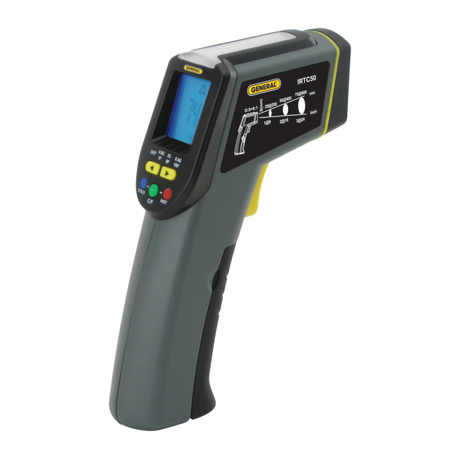
The IRTC50 is a pistol-grip instrument that measures the surface temperature of an object from a distance by using an infrared (IR) sensor to quantify its thermal radiation. This remote measurement capability allows you to safely determine the temperature of very hot or cold surfaces, inaccessible or hard-to-reach objects, and toxic substances. A laser pointer in the shape of a starburst defines the target area (spot) whose temperature is actually being measured, improving the accuracy of readings. All measurements are displayed on a backlit LCD.
The IRTC50's scanning function, which is made possible by the three-color light panel on the top of the instrument, is an especially convenient and time-saving feature. In many applications—such as detecting thermal leaks in a house or a batch of undercooked food—the absolute temperature of a surface is less important than the temperature of the surface relative to surfaces around it.
What the IRTC50 does extremely well and quickly is place scanned targets into one of three color-coded categories: green for targets within a temperature band (or window) centered on a reference (normal) temperature, red for targets hotter than the upper edge of the band, and blue for targets colder than the lower edge of the band. The instrument simultaneously uses sound to categorize scanned targets by temperature. Colder-than-normal targets generate a slow beeping sound, hotterthan-normal targets produce fast beeping, and targets close to the reference temperature do not activate the beeper.
The IRTC50 automatically enters scanning mode when you squeeze and hold the trigger for three seconds. Doing so sets the reference temperature to the measured temperature of the laser's target at that time. In practice, what most professionals use as a reference is something they consider at "normal" temperature—an interior wall of a room, for example. After you squeeze and hold the trigger for three seconds, the word "REF" appears on the LCD next to the measured temperature. More importantly, however, the light panel on the top of the IRTC50 initially glows green to indicate that the surface being scanned is within the temperature window.
In scanning mode, the "setpoint bandwidth"—the technical term for the width of the temperature window centered on the reference temperature—is preset at 1°F (0.5°C), but you can widen the window to 5°F (3°C) or 10°F (5.5°C) if a wider window would better suit your application. Typically, the narrowest setpoint band (1°F/0.5°C) is used to monitor the temperature of processes requiring precise quality control (food preparation, for example). The wider bands of ±5°F (3°C) and ±10°F (5.5°C) are used to detect wider deviations, for example in energy auditing.
What distinguishes the IRTC50 from other scanning IR thermometers is that one squeeze of its trigger simultaneously captures a reference temperature and launches scanning mode. Once you have established a reference temperature and a setpoint bandwidth, you can begin to scan other objects within view and quickly determine by sight and sound whether they are hotter or colder than the reference temperature ± the setpoint bandwidth.
The advantage of using the color of the light panel (red, green or blue) and the speed of the beeper (fast, silent or slow) to indicate whether the surface you're targeting is above, at or below the reference temperature ± the setpoint bandwidth is that you keep your eye on the target—rather than the display reading—while you scan. With practice, you can learn to correlate the beeper's frequency with temperature and to note the color of the light panel out of the corner of your eye while maintaining focus on your targets.
KEY FEATURES & BENEFITS
- In scanning mode, IRTC50 lets you focus on the laser's target instead of thedisplay reading. The color of the light panel (red, green or blue) and the speed of the beeper (fast, silent or slow) tell you—without having to look at the LCD— whether the temperature of the surface you're targeting is above, within or below the reference temperature ± the setpoint bandwidth.
- Choice of three setpoint bandwidths: 1°F (default), 5°F and 10°F (0.5°, 3° and 5.5°C)
- Ideal for making relative temperature measurements—such as in energyauditing
- One pull of the trigger automatically captures a reference temperature andlaunches scanning mode
- Star Burst laser pattern helps determine the optimum distance to a target
- Large backlit LCD automatically holds its reading when the trigger is released
- 3% or better accuracy in conventional IRT mode
PRODUCT OVERVIEW
Fig. 1 shows all of the controls, indicators and physical features of the IRTC50. Fig. 2 shows all of the icons and text that may appear on the LCD. Familiarize yourself with the locations and functions of the controls and the meanings of the display icons before moving on to the Setup Instructions and Operating Instructions.

- Star Burst laser pointer
- Infrared sensor and lens
- Measurement trigger: Squeeze to power unit on; squeeze and hold for 3 seconds to power unit on and acquire a reference temperature
- Battery compartment
- Light panel (glows green/red/blue to indicate whether temperature of target is within/above/below reference temperature
± setpoint bandwidth - Backlit LCD
- Laser identification/certification/ warning/safety Labels (on left side); see above right
![]()


- Reference temperature line
- Low battery icon
- Temperature unit (°F or °C)
- Indicates measurement in progress
- Scanned/held temperature
- Selected setpoint band indicators (each points to label directly below)
- T setpoint bandwidth selectors
- Two-function button: Pressed briefly with instrument on, toggles unit of scanned/held and reference temperatures between °F (default) and °C; pressed and held for 3 seconds, powers instrument off
SETUP INSTRUCTIONS
INSTALL BATTERY
The IRTC50's battery compartment (Fig. 1, Callout D) is below the trigger and accessible from the front of the grip. Before installing the "9V" battery included in the blister pack, remove the plastic covering its terminals.
To install the battery:
- Open the battery compartment by placing your thumb and forefinger in theindentations on the sides of the grip and pulling the top of the compartment forward.
- Plug the "9V" battery into the wired socket inside the compartment. Theterminals of the battery and the socket mate in only one way, with the smaller male terminal plugging into the larger female terminal.
- Close the battery compartment cover by pushing its top against the grip until thecover snaps shut.
OPERATING INSTRUCTIONS
SCAN MODE
- Point the IRTC50 at an interior wall of the room you are in. (If the LCD does not illuminate, the battery is dead and must be replaced; see above for instructions.)
- Squeeze and hold the yellow measurement trigger for more than three seconds, until the light panel on the top of the unit glows green. The unit will acquire the temperature of the wall as a reference and select 1°F (0.5°C) as the default setpoint bandwidth. The wall's temperature and the word SCAN will be displayed on the LCD in large digits below the reference temperature, indicated by the text REF. Until you aim at another surface, the light panel on the top of the IRTC50 will continue to glow green to indicate that the target's temperature is within 1°F (0.5°C) of the reference temperature.
- Keep squeezing the trigger as you scan other surfaces or objects in the room. Aim at a lit lamp or overhead light and watch the color of the light panel change from green to red. Red indicates that the lamp or light is at least 1°F (0.5°C) hotter than the wall. Hear the beeper sound.
- Keep squeezing the trigger as you scan the interior of your refrigerator or a register of an operating air conditioner. Watch the color of the light panel change to blue, indicating that the new target is at least 1°F (0.5°C) cooler than the wall. Hear the beeper sound, but more slowly than before.
- Release the trigger and watch and wait. The word SCAN will disappear from the LCD, but the reference temperature and the last measurement will remain. After 15 seconds, the LCD backlight will silently turn off while both temperature readings remain visible. After 60 seconds, the unit will sound two beeps and power off to extend battery life.
- To change the setpoint bandwidthu while continuing to operate in Scan Mode, press the yellow button (Fig. 2, Callout G) once to choose 5°F (3°C) or twice to choose 10°F (5.5°C). Note that the setpoint bandwidth indicator (Fig. 2, Callout F) moves to track your change(s).
- To change the reference temperature, you must first power off the IRTC50 by pressing and holding the green C/F button (Fig. 2, Callout H). Then repeat Steps 1 and 2.
CONVENTIONAL IRT MODE
- Power on the IRTC50 by squeezing and holding the yellow measurement trigger.
- When the LCD illuminates, exit Scan mode (the instrument's default state att power on) by pressing the yellow button once to move the setpoint band indicator (Fig. 2, Callout F) above the wordOFF.
- In Conventional IRT mode, the light panel will remain dark as you measure anddisplay absolute temperatures without relating them to a reference. The beeper will sound once and the wordSCAN will appear each time you squeeze the trigger to make a measurement.
- To change the measurement unit from the default °F to °C, briefly press the C/F button (Fig. 2, Callout H). To return to Fahrenheit units, press the button again.
OPERATING TIPS
The first few times you use the IRTC50 in Scan mode, don't be too concerned about which setpoint bandwidth to choose. With experience you will learn whether a narrow (1°F), normal (5°F) or wide (10°F) setpoint bandwidth is best for your particular application. As part of your education, experiment with the setpoint bandwidth. For example, widen it from 1°F to 5°F and note that some targets that caused the light panel to glow red before produce green lights now.
Remember that the reference temperature you acquire and the setpoint bandwidth you choose disappear if you allow just one minute to go by without pulling the trigger. For this reason, you can expect to repower the IRT often.
Practice using the Star Burst laser to define the size of your targets with the goal of improving your measurement accuracy. The diameter of the Star Burst is about half that of the overall spot diameter. For best results, move close enough to the target so its diameter appears about twice the diameter of the Star Burst.
The IRTC50 cannot make accurate measurements if there is glass or plastic between it and the target.
When the ambient temperature exceeds the IRTC50's maximum operating temperature (104°F/40°C), the beeper will sound quickly (at 2 Hz) and the display will show the following error message: ErAH.
When the ambient temperature falls below the IRT's minimum operating temperature (32°F/0°C), the instrument will beep slowly (at 1 Hz) and the display will show the following error message: ErAL.
When the temperature of a target exceeds the specified maximum (428°F/220°C), the beeper will sound quickly and the display will show the following error message: ErOH.
When the temperature of a target falls below the specified minimum (-40°F/-40°C), the beeper will sound quickly and the display will show the following error message: ErOL.
SPECIFICATIONS
| Temperature Measurement Range | -40° to 428°F (-40° to 220°C) |
| Temperature Measurement Accuracy | ±4°F/C or ±2% of reading >32°F (0°C) ±3°F/C or ±3% of reading <32°F (0°C) |
| Sensitivity | 1°F (0.5°C) |
| Repeatability | ±1.5°F (1°C) |
| Display Resolution | 0.1° (F or C) |
| Distance-to-Spot Ratio | 8:1 |
| Emissivity | Fixed at 0.95 |
| Response Time | 500 ms |
| Laser Pointer Wavelength | 655nm |
| Laser Power | <3mW |
| Operating Temperature | 32° to 104°F (0° to 40°C) @ 10 to 90% RH |
| Storage temperature (not including battery) | -40° to 122°F (-20° to 50°C) |
| High Temperature Beeper Frequency | 2 Hz |
| Low Temperature Beeper Frequency | 1 Hz |
| Current Consumption | <30mA, max |
| Backlight Auto Shutoff Trigger | 15 seconds of inactivity |
| Instrument Auto Power Off Trigger | 60 seconds of inactivity |
| Dimensions | 5.31 x 1.65 x 6.81 in. (135 x 42 x 173mm) |
| Weight | 6.24 oz. (177g) (without battery) |
| Power Source | (1) "9V" battery (included) |
MAINTENANCE TIPS
Clean the infrared sensor lens (Fig. 1, Callout B) often—but never use a solvent.
Abrupt temperature changes will cause condensation and possible vapor penetration. Clean the LCD after the vapor evaporates. Blow off loose particles with clean, compressed air. Gently brush remaining debris away with a lens hair brush.
To clean the housing, use a moist cotton swab or wet sponge. Avoid excessive amounts of water and corrosive gas or liquids.
Remove the battery if you don't expect to use the IRT for an extended period of time (months or years).
Do not drop or disassemble the unit or immerse it in water.
SAFETY INSTRUCTIONS

Use of controls or adjustments or performance of procedures other than those specified herein may result indangerous radiation exposure.
The IRTC50 is a Class 3R laser product that emits less than 3mW of radiation. Avoid looking directly at the laser pointer. U.S. law prohibits pointing a laser beam at aircraft; doing so is punishable by a fine of up to $10,000 and imprisonment.
The laser may cause discomfort if viewed directly. Your eyes' natural aversion reflex will prevent you from looking at the beam long enough to cause harm. However, keep the IRTC50 out of the hands of children, especially if you have pets.
Never stare at the laser beam through binoculars or a magnifying glass.
Documents / ResourcesDownload manual
Here you can download full pdf version of manual, it may contain additional safety instructions, warranty information, FCC rules, etc.
Advertisement


Need help?
Do you have a question about the IRTC50 and is the answer not in the manual?
Questions and answers