Advertisement
Table of Contents
1. Warning..............................................................................2
2. Specifications....................................................................3
3. Troubleshooting Guide.....................................................4
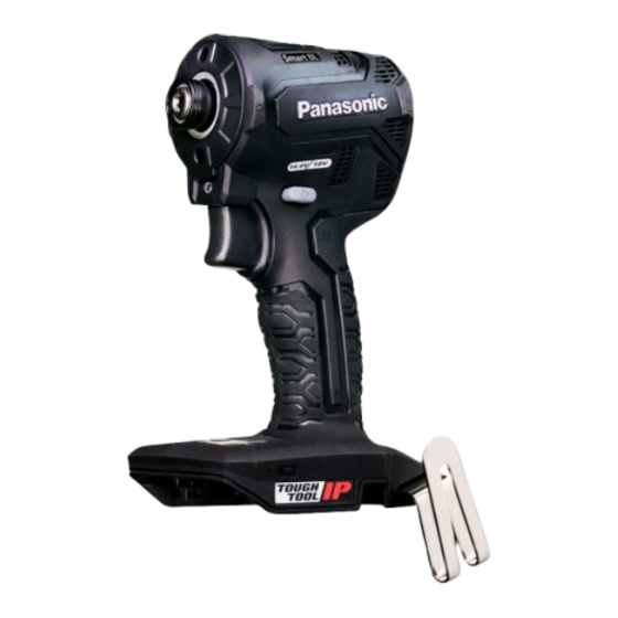
Cordless Impact driver
EY1PD1
Model No.
Europe
Page
4. Disassembly and Assembly Instructions....................... 7
5. Exploded View and Replacement Parts List................ 11
© Panasonic Corporation 2022. All rights reserved.
Unauthorized copying and distribution is a violation of law.
Order No.PTD2210E02CE
Page
Advertisement
Table of Contents

Summary of Contents for Panasonic EY1PD1
-
Page 1: Table Of Contents
Table of Contents Page Page 1. Warning................2 4. Disassembly and Assembly Instructions....... 7 2. Specifications..............3 5. Exploded View and Replacement Parts List....11 3. Troubleshooting Guide.............4 © Panasonic Corporation 2022. All rights reserved. Unauthorized copying and distribution is a violation of law. -
Page 2: Warning
1 Warning Caution: • Pb free solder has a higher melting point that standard solder; Typically the melting point is 50 - 70°F (30 - 40°C) higher. Please use a soldering iron with temperature control and adjust it to 750 ± 20°F (400 ± 10°C). In case of using high temperature soldering iron, please be careful not to heat too long. -
Page 3: Specifications
2 Specifications - 3 -... -
Page 4: Troubleshooting Guide
3 Troubleshooting Guide 3.1 Troubleshooting Guide See 3.2. Criteria for Determining. - 4 -... - Page 5 3.2. Criteria for Determining When to Replace Worn Parts ① Hammer Wear The parts shown in the figure below will wear out as they collide with the anvil. Replace the hammer when the replacement level is reached. Replacement level Wear Wear Wear Chamfer width...
- Page 6 3.3. tool 3.3.1. 3.3.2. ●Check that the tool operates normally according to the settings on the control panel. ( Please refer to the operating instructions for details). ① Press the light button and check that the light switches in the following order: Light on ➡...
-
Page 7: Disassembly And Assembly Instructions
[Strictly observe] Check and understand the disassembly/assembly procedures and exploded view in advance. [Strictly observe] To reduce the risk of injury, always remove battery pack before removing/installing the tool. [Strictly observe] Manage all parts and make sure that no parts are left unattached at the time of assembling. [Note] Work while keeping information on the disassembly process using a digital camera as needed. - Page 8 4.3. Removing the LED cover and drive unit. Motor mounting plate 1. Remove the LED cover. (The LED cover can be easily removed by lifting the tip of the drive unit) LED cover. NOTE: (When Assembling) Align the position 2. Lift up the drive unit and motor assembly and remove the LED.from the housing. Motor assembly NOTE: (When disassembling the LED). Exercise care not to cut the lead wires.
- Page 9 4.5. Precautions When Applying Grease Apply grease (CALFOREX) to the indicated by the shaded area. Apply grease to the Apply grease to the outer circumference Fill grease up to the hammer sliding surfaces of the of gear rod. surface. thrust plate and anvil. Apply grease to the section of the side surface of the anvil.
- Page 10 4.6. Wiring and Assembly Points. Wiring process from the switch assembly to the circuit board Wiring process under the switch assembly The lead wire must not get caught when operating the F/R Complete the wiring process of the selector handle. LED leads, black wires, and white wires in sequence.
-
Page 11: Exploded View And Replacement Parts List
Model NO. : EY1PD1 Exploded View Production marking 2 10 0001 Serial No. Month Year (Last 1 digit) 2022 Year... - Page 12 Model NO. : EY1PD1 Parts list...


Need help?
Do you have a question about the EY1PD1 and is the answer not in the manual?
Questions and answers