Table of Contents
Advertisement
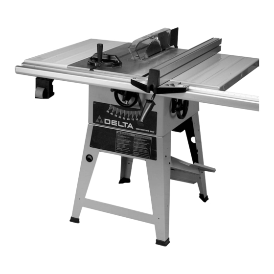
10" Contractor's Saw
(Model 36-465)
NOTE: Shown with UniRip
®
Fence System
PART NO. 422-19-651-0056 - 03-20-04
Copyright © 2004 Delta Machinery
To learn more about DELTA MACHINERY
visit our website at: www.deltamachinery.com.
For Parts, Service, Warranty or other Assistance,
1-800-223-7278 (
1-800-463-3582).
please call
In Canada call
Advertisement
Table of Contents

Related Manuals for Delta 36-465


Summary of Contents for Delta 36-465
- Page 1 NOTE: Shown with UniRip ® Fence System PART NO. 422-19-651-0056 - 03-20-04 Copyright © 2004 Delta Machinery To learn more about DELTA MACHINERY visit our website at: www.deltamachinery.com. For Parts, Service, Warranty or other Assistance, 1-800-223-7278 ( 1-800-463-3582). please call...
-
Page 2: General Safety Rules
If you have any questions relative to a particular application, DO NOT use the machine until you have first contacted Delta to determine if it can or should be performed on the product. - Page 3 13. USE RECOMMENDED ACCESSORIES. The use of accessories and attachments not recommended by Delta may cause damage to the machine or injury to the user. 14. USE THE PROPER EXTENSION CORD. Make sure your extension cord is in good condition. When using an extension cord, be sure to use one heavy enough to carry the current your product will draw.
-
Page 4: Save These Instructions
15. NEVER have any part of your body in line with the path of the saw blade. 16. NEVER REACH AROUND or over the saw blade. 17. NEVER attempt to free a stalled saw blade without first turning the machine “OFF”. 18. PROPERLY SUPPORT LONG OR WIDE workpieces. -
Page 5: Power Connections
A separate electrical circuit should be used for your machines. This circuit should not be less than #12 wire and should be protected with a 20 Amp time lag fuse. If an extension cord is used, use only 3-wire extension cords which have 3- prong grounding type plugs and matching receptacle which will accept the machine’s plug. -
Page 6: Extension Cords
3. Grounded, cord-connected tools intended for use on a supply circuit having a nominal rating between 150 - 250 volts, inclusive: If the tool is intended for use on a circuit that has an outlet that looks like the one illustrated in Fig. C. The tool will have a grounding plug that looks like the plug illustrated in Fig. -
Page 7: Functional Description
Delta Model 36-465 is a 10" Contractor’s Saw 3-1/8" (79mm) at 90° and 2-1/8" (54mm) at 45° for clean cutting of stock within the capacities of the saw. Delta Model 36-465 includes; basic machine, sturdy steel stand, integral dust chute, UniRip... - Page 8 UNPACKING AND CLEANING 1. Contractor’s Saw 2. Blade Tilting Handwheel 3. Handwheel Lock Knob 4. Blade Guard and Splitter Assembly 5. Table Insert 6. Miter Gage 7. Miter Gage Handle 8. Miter Gage Handle 9. Splitter Mounting Bracket 10. 1/4-20 x 3/4" Hex Head Bolts (2) 11.
- Page 9 UNPACKING AND CLEANING Fig. 3 Fig. 3A Continued 1. Combination Dust Chute/ Support Panel 2. Motor Pulley 3. Motor 4. Pulley Guard 5. Drive Belt 6. Spring 7. Pins (2) for Mounting Motor 8. Motor Mounting Plate 9. 5/16 Lockwashers (4) 10.
-
Page 10: Saw Assembly
DO NOT OPERATE THIS MACHINE UNTIL YOU READ AND UNDERSTAND THE ENTIRE INSTRUCTION MANUAL. MAKE SURE THE SAW IS SECURELY ATTACHED TO THE STAND BEFORE PERFORMING ANY CUTTING OPERATIONS. ASSEMBLING SAW STAND 1. Assemble the dust chute and support panel (A) Fig. -
Page 11: Motor Assembly
(E) assembled to the saw. Fig. 9 The motor shipped with your saw is a 1-1/2 H.P. at 115 volts or 2 H.P. at 230 volts, Ball Bearing, Capacitor Start/Capacitor Run motor. This motor has been especially selected to best supply power to your machine, and the relative safety of the machine is enhanced by its use. - Page 12 (B) and rotate motor mounting plate (A) until pins (C) are engaged in holes (D) Fig. 12, of motor mounting plate (A). 4. Fig. 14 illustrates the motor and motor mounting plate assembled to the rear of the saw. Fig. 12 Fig. 13 Fig. 14...
- Page 13 ASSEMBLING MOTOR PULLEY, BELT PULLEY GUARD, AND DRIVE BELT DISCONNECT MACHINE FROM THE POWER SOURCE. 1. Remove the motor shaft key that is taped to the motor. 2. Insert the key (A) Fig. 15 in the keyway on the motor shaft.
- Page 14 IMMEDIATELY AFTER ASSEMBLING THE BELT, RAISE THE SAW BLADE TO ITS MAXIMUM HEIGHT AND TILT THE SAW BLADE TO 45°. CHECK TO SEE IF THE MOTOR (J) FIG. 20 IS BELOW THE TOP OF THE TABLE SURFACE (K).
- Page 15 (B) and flat washers. Do not completely tighten the two bolts (B) at this time. 2. Raise saw arbor to its highest position. With wrenches supplied, remove the saw blade from the saw. Refer to section “CHANGING THE SAW BLADE” of this manual.
- Page 16 5. If alignment is necessary, loosen the two screws (F) Fig. 27, align bracket (D) with the arbor flange (E), and tighten screws (F). 6. Loosely assemble large washer and bolt (C) Fig. 27, to the inside splitter bracket. This bolt and washer was removed in STEP 3.
- Page 17 See section “CHANGING SAW BLADE.” 10. Use a straight edge (E) to check to see if the saw blade is aligned with the rear of the splitter (G) in Figs. 32 and 33. If alignment is necessary, loosen the bolts (A) Fig.
-
Page 18: Operating Controls
(S). Tighten after fence rail assembly. STARTING AND STOPPING SAW 1. The on/off switch is located underneath the switch shield (A) Fig. 37. To turn the saw “ON”, move switch trigger (B) to the up position. 2. To turn the saw “OFF”, push down on switch shield (A) Fig. 38. - Page 19 5. With the power still "OFF", lift the blade guard (E) Fig. 44 and raise the saw blade (F). Using a straight edge or square (G) against the saw blade (F), position the edge of the guide rails so the separation (H) is in line with the saw blade.
-
Page 20: Assembling Rip Fence
If it becomes necessary to remove the end caps, use a wide blade screwdriver. 9. Align holes (S) Fig. 47 in saw table and extension wings with the six holes in the rear guide rails (N). Fasten rear guide rails to saw table and extension wings with six 3/8-16 x 1"... - Page 21 RIP FENCE OPERATION AND ADJUSTMENTS The rip fence can be used on either side of the saw blade. The most common location is on the right side and is guided by means of guide rails which are fastened to the front and rear of the table.
- Page 22 3. Using a square (G) Fig. 57, and a straight edge (H), check to see if the rip fence (B) is perpendicular to the saw table and that the rip fence body is level with the saw table. If a perpendicular adjustment is necessary, tighten or loosen either of two screws (K) Fig 57 until the fence is perpendicular and level with the saw table.
-
Page 23: Operation And Adjustments
OPERATION AND ADJUSTMENTS RAISING AND LOWERING THE BLADE To raise the saw blade, loosen lock knob (A) Fig. 59, and turn the blade raising handwheel (B) clockwise. When the blade is at the desired height, tighten lock knob (A). To lower the blade, loosen lock knob (A) Fig. 59, and turn the handwheel (B) counterclockwise. - Page 24 CHECKING BLADE ALIGNMENT The saw has been aligned at the factory so the saw blade is parallel to the miter gage slots; however, it is recommended to check the alignment before initial operation as follows: DISCONNECT MACHINE FROM POWER SOURCE.
- Page 25 2. Remove table insert (C) Fig. 66, and raise saw blade to its maximum height. 3. Place the open end wrench (B) Fig. 66 on the flats of the saw arbor to keep the arbor from turning, and use wrench (A), to turn the arbor nut toward the front of the saw.
- Page 26 ADJUSTING TABLE INSERT DISCONNECT MACHINE POWER SOURCE. Place a straight edge across the table at both ends of the table insert. The table insert (A) Fig. 69 should always be level with the table. If an adjustment is necessary, turn the adjusting screws (B). Four adjusting screws (B) are supplied in the table insert.
- Page 27 The following information describes the safe and proper method for performing the most common sawing operations. THE USE OF ATTACHMENTS AND ACCESSORIES NOT RECOMMENDED BY DELTA MAY RESULT IN THE RISK OF INJURY TO THE USER OR OTHERS.
- Page 28 The saw blade guard must be used. On Delta saws, the guard has anti-kickback fingers to prevent kickback and a splitter to prevent the wood kerf from closing and binding the blade.
- Page 29 1 inch facing. 3. Position the wood-facing over the cutterhead with the cutterhead below the surface of the table. Turn the saw on and raise the cutterhead. The cutterhead will cut its own groove in the wood-facing. Fig. 84 shows a typical moulding operation.
- Page 30 2. Attach the dado head set (D) Fig. 88, to the saw arbor. NOTE: THE OUTSIDE ARBOR FLANGE CAN NOT BE USED WITH THE DADO HEAD SET, TIGHTEN THE ARBOR NUT AGAINST THE DADO HEAD SET BODY.
-
Page 31: Constructing A Featherboard
Always replace the guard and splitter assembly when the non thru-sawing operation is completed. Further information on the safe and proper operation of table saws is available in the Delta “Getting the Most Out of Your Table Saw” How- To Book, Catalog No. -
Page 32: Constructing A Push Stick
CONSTRUCTING A PUSH STICK When ripping work less than 4 inches wide, a push stick should be used to complete the feed and could easily be made from scrap material by following the pattern shown in Fig. 92. -
Page 33: Dust Chute
2. Arbor wrenches (C) Fig. 93, can be stored on one of the two notched legs. DUST CHUTE The saw stand support panel (D) Fig. 94 also serves as a natural built-in dust chute. This dust chute (D) allows the sawdust to conveniently escape out the rear of the saw stand and away from the work area. - Page 34 Two Year Limited New Product Warranty Delta will repair or replace, at its expense and at its option, any new Delta machine, machine part, or machine accessory which in normal use has proven to be defective in workmanship or material, provided that the customer returns the product prepaid to a Delta factory service center or authorized service station with proof of purchase of the product within two years and provides Delta with reasonable opportunity to verify the alleged defect by inspection.
- Page 35 NOTES...
- Page 36 Phone: (604) 420-0102 Fax: (604) 420-3522 The following are trademarks of PORTER-CABLE • DELTA (Las siguientes son marcas registradas de PORTER-CABLE • DELTA S.A.) (Les marques suivantes sont des marques de fabriquant de la PORTER-CABLE • DELTA): Auto-Set Contractor’s Saw II™, Delta ®...