YORK YK Series, YK MaxE Manual
- Operation manuals (220 pages) ,
- Operation and maintenance (38 pages) ,
- Operation and maintenance manual (36 pages)
Advertisement
- 1 Description of system and fundamentals of operation
- 2 System operating procedures
- 3 System components description
- 4 Operational maintenance
-
5
Troubleshooting
- 5.1 ABNORMALLY HIGH DISCHARGE PRESSURE
- 5.2 ABNORMALLY LOW SUCTION PRESSURE
- 5.3 HIGH EVAPORATOR PRESSURE
- 5.4 NO OIL PRESSURE WHEN SYSTEM START BUTTON PUSHED
- 5.5 UNUSUALLY HIGH OIL PRESSURE DEVELOPS WHEN OIL PUMP RUNS
- 5.6 OIL PUMP VIBRATES OR IS NOISY
- 5.7 REDUCED OIL PUMP CAPACITY
- 5.8 OIL PRESSURE GRADUALLY DECREASES
- 5.9 OIL PRESSURE SYSTEM CEASES TO RETURN AN OIL/REFRIGERANT SAMPLE
- 5.10 OIL PUMP FAILS TO DELIVER OIL PRESSURE
- 6 Maintenance
- 7 Preventative maintenance
- 8 Important
- 9 Documents / Resources
Description of system and fundamentals of operation

System operation description (See Figure 3)
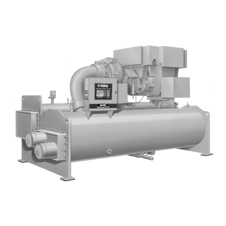
The YORK Model YK MaxE Chiller is commonly applied to large air conditioning systems, but may be used on other applications. The chiller consists of an open motor mounted to a compressor (with integral speed increasing gears), condenser, evaporator and variable flow control.
The chiller is controlled by a modern state of the art Microcomputer Control Center that monitors its operation. The Control Center is programmed by the operator to suit job specifications. Automatic timed start-ups and shutdowns are also programmable to suit nighttime, weekends, and holidays. The operating status, temperatures, pressures, and other information pertinent to operation of the chiller are automatically displayed and read on a graphic display. Other displays can be observed by pressing the keys as labeled on the Control Center. The chiller with the OptiView™ Control Center is compatible with an electro-mechanical starter, YORK Solid State Starter (optional), or Variable Speed Drive (optional).
In operation, a liquid (water or brine to be chilled) flows through the evaporator, where boiling refrigerant absorbs heat from the liquid. The chilled liquid is then piped to fan coil units or other air conditioning terminal units, where it flows through finned coils, absorbing heat from the air. The warmed liquid is then returned to the chiller to complete the chilled liquid circuit.
The refrigerant vapor, which is produced by the boiling action in the evaporator, flows to the compressor where the rotating impeller increases its pressure and temperature and discharges it into the condenser. Water flowing through the condenser tubes absorbs heat from the refrigerant vapor, causing it to condense. The condenser water is supplied to the chiller from an external source, usually a cooling tower. The condensed refrigerant drains from the condenser into the liquid return line, where the variable orifice meters the flow of liquid refrigerant to the evaporator to complete the refrigerant circuit.
Figure 2: Compressor prerotation vanes

The major components of a chiller are selected to handle the refrigerant, which would be evaporated at full load design conditions. However, most systems will be called upon to deliver full load capacity for only a relatively small part of the time the unit is in operation.
Capacity control
The major components of a chiller are selected for full load capacities, therefore capacity must be controlled to maintain a constant chilled liquid temperature leaving the evaporator. Prerotation vanes (PRV), located at the entrance to the compressor impeller, compensate for variation in load. See Figure 2.
The position of these vanes is automatically controlled through a lever arm attached to an electric motor located outside the compressor housing. The automatic adjustment of the vane position in effect provides the performance of many different compressors to match various load conditions from full load with vanes wide open to minimum load with vanes completely closed.
Figure 3: Refrigerant flow through chiller

System operating procedures
Oil heaters
If the oil heater is de-energized during a shutdown period, it must be energized for 12 hours prior to starting compressor, or remove all oil and recharge compressor with new oil. (See Oil charging procedure.)
Oil heater operation
The oil heater operation is controlled by the OptiView Control Center. The heater is turned on and off to maintain the oil temperature differential to a value 50°F (27.8°C) above the condenser saturation temperature. This is the target value and if the oil temperature falls to 4°F (2.2°C) or more below the target, the heater is turned on. It is turned off when the oil temperature increases to 3°F (1.7°C) above the target value.
If the target value is greater than 160°F (71°C), the target defaults to 160°F (71°C). If the target value is less than 110°F (43.3°C), it defaults to 110°F (43.3°C).
To prevent overheating of the oil in the event of a control center component failure, the oil heater thermostat (1HTR) is set to open at 180°F (82°C).
Checking the oil level
In the oil reservoir
Correct operating oil level – During operation, the oil level should fall to the Operating Range identified on the vertical oil level indicator label. See Figure 4.
Figure 4: Oil level indicator

- If the oil level during operation is in the Over Full region of the oil level indicator, oil should be removed from the oil reservoir. This reduces the oil level to the Operating Range.
- If the oil level during operation is in the Low Oil region of the oil level indicator, oil should be added to the oil reservoir. See Oil charging procedure.

Comply with EPA and Local regulations when removing or disposing of refrigeration system oil.
START-UP PROCEDURE
Pre-Starting Prior to starting the chiller, observe the OptiView Control Center. Make sure the display reads SYSTEM READY TO START.
To pre-start the chiller, use the following procedure:
- Oil Heater – The oil heater must be energized for 12 hours before starting the chiller.
- Prior to start, the clock must be programmed for the proper day and time. Any setpoints which are desired to be changed may be programmed. All Control Center setpoints should be programmed before the chiller is started. Refer toForm 160.54-O1.
Vent any air from the chiller water boxes before starting the water pumps. Failure to do so results in pass baffle damage.
Start-up
- If the chilled water pump is manually operated, start the pump. The Control Center will not allow the chiller to start unless chilled liquid flow is established through the unit. (A field supplied chilled water flow switch is required.) If the chilled liquid pump is wired to the Microcomputer Control Center the pump automatically starts, therefore, this step is not necessary.
- To start the chiller, press the COMPRESSOR START switch. This switch automatically springs return to the RUN position. (If the unit was previously started, press the STOP/RESET side of the COMPRESSOR switch and then press the START side of the switch to start the chiller.) When the start switch is energized, the Control Center is placed in an operating mode and any malfunction will be noted by messages on a graphic display.
 NOTE
NOTE
Any malfunctions which occur during STOP/RESET are also displayed.
When the chiller is shut down, the prerotation vanes will close automatically to prevent loading the compressor on start-up.
When the chiller starts to operate, the following automatic sequences are initiated: See Figure 5 and Figure 6, Chiller Starting and Shutdown Sequence Chart.
- The OptiView Control Center display message will readSYSTEM PRELUBE for the first 50 seconds of the starting sequence.
- The oil pump will start to circulate oil for a 50 second pre-run to establish oil flow and adequate lubrication to all bearings, gears, and rotating surfaces within the compressor.
The high and low oil pressure transducers (OP) and the oil temperature sensor (RT3) will sense any malfunction in the lubrication system. - The anti-recycle timer (non-VSD Chillers only) software function will operate after the 50 seconds of pre-run time. At this time, the timer will be initiated and will run for 30 minutes after the compressor starts. If the chiller shuts down during this period of time, it cannot be started until the timer completes the 30 minute cycle.
- The chilled liquid pump contacts will close, start-ing the chilled liquid pump, to allow liquid flow through the evaporator when theCOMPRESSOR start switch is energized.
- After the first 50 seconds of operation, the compressor will start.
- 6. For display messages and information pertaining to the operation of the OptiView Control Center, refer to Form 160.54-O1.
Figure 5: Chiller starting sequence and shutdown sequence (em starter and solid state starter)
")
** Not for all shutdowns. Refer to the display messages of this manual.
Figure 6: Chiller starting sequence and shutdown sequence (variable speed drive)
")
** Not for all shutdowns. Refer to the display messages of this manual.
Chiller operation
After the compressor reaches its operating speed, the Prerotation Vanes will begin to open under the control of the Microprocessor Board which senses the leaving chilled liquid temperature. The unit capacity will vary to maintain the leaving CHILLED LIQUID TEMPERATURE setpoint. The Prerotation Vanes are modulated by an actuator under the control of the Microprocessor Board. The vane control routine employs proportional plus derivative (rate) control action. A drop in chilled liquid temperature will cause the actuator to close the Prerotation Vanes to decrease chiller capacity. When the chilled liquid temperature rises, the actuator will open the Prerotation Vanes to increase the capacity of the chiller.
However, the current draw (amperes) by the compressor motor cannot exceed the setting of the % CURRENT LIMIT at any time during the unit operation, since the Microcomputer Control Center 40 to 100% three-phase peak current limit software function, plus the 3-phase 100% solid state overload current limiter (CM-2), on Electro-Mechanical Starter applications, or the Solid State Starter current Limit function will override the temperature control function and prevent the Prerotation Vanes from opening beyond the % CURRENT LIMIT setting.
If the load continues to decrease, after the Prerotation Vanes are entirely closed, the chiller will be shut down by the Leaving Chilled Liquid – Low Temperature Control.
Condenser Water Temperature Control
The YORK MaxETM chiller is designed to use less power by taking advantage of lower than design temperatures that are naturally produced by cooling towers throughout the operating year. Exact control of condenser water such as a cooling tower bypass, is not necessary for most installations. The chiller requires only that the minimum condenser water temperature be no lower than the value determined by referring to the formula below:
Min. ECWT = LCWT – C RANGE + 17ºF Min. ECWT = LCWT – C RANGE + 9.4ºC where:
ECWT = Entering Condensing Water Temperature
LCWT = Leaving Chilled Water Temperature C Range = Condensing water temperature range at the given load condition.
At start-up, the entering condenser water temperature may be as much as 25°F (14°C) colder than the standby return chilled water temperature. Cooling tower fan cycling will normally provide adequate control of the entering condenser water temperature on most installations.
Operating log sheet
A permanent daily record of system operating conditions (temperatures and pressures) recorded at regular intervals throughout each 24 hour operating period should be kept.
An optional status printer is available for this purpose or Figure 7 shows a log sheet used by YORK Personnel for recording test data on chiller systems. It is available from the factory in pads of 50 sheets each under Form 160.44-F7 and may be obtained through the nearest YORK office. Automatic data logging is possible by connecting the optional printer and programming the DATA LOGGER function.
An accurate record of readings serves as a valuable reference for operating the system. Readings taken when a system is newly installed will establish normal conditions with which to compare later readings.
For example, an increase in condenser approach temperature (condenser temperature minus leaving condenser water temperature) may be an indication of dirty condenser tubes.
Operating instructions
By following a regular inspection using the display readings of the Microcomputer Control Center, and maintenance procedure, the operator will avoid serious operating difficulty. The following list of inspections and procedures should be used as a guide. Refer to Form 160.54-MR1 and see Table 1.
Daily
- Check the OptiView Control Center display. Log the date, time, run hours, and number of starts.
- Use the daily log in the YK centrifugal liquid chiller log sheet,160.54-MR1, to log all of the unit operating data that is outlined in the log. Use this data for the following comparisons:
- Compare the entering and leaving condenser water temperatures with the job design conditions. Check the condenser water temperatures on the System screen.
- Compare the entering and leaving chilled liquid temperatures and evaporator pressure with the job design conditions. Check the chilled liquid temperatures on the System screen.
- Check the condenser saturation temperature on the System screen. The condenser saturation temperature is based on the condenser pressure that is sensed by the condenser transducer.
Figure 7: Liquid chiller log sheets

*NOTE: These items can be printed by an electronic printer connected to the Microboard and pressing the PRINT key on the Keypad, or automatically using the Data Logger feature.
- Check the compressor discharge temperature on the System screen. During normal operation, the discharge temperature does not exceed 220°F (104°C).
- Check the compressor motor current on the Compressor screen.
Weekly
- Check the refrigerant charge. Refer to Form 50.40-O3.
- Check for any signs of dirty or fouled condenser tubes. The temperature difference between the water leaving the condenser and the saturated condensing temperature must not exceed the difference recorded for a new unit by more than 4°F (2.2°C).
Table 1: Maintenance requirements
| Maintenance requirements for YORK YK chillers | |||||
| Procedure | Daily | Weekly | Monthly 3 | Yearly | Other |
| Record the operating conditions (on applicable Log Form). | X | ||||
| Check the oil levels. | X | ||||
| Check the refrigerant levels. | X | ||||
| Check the oil return system operation. | X | ||||
| Check the operation of the motor starter. | X | ||||
| Check the sump heater and thermostat operation. | X | ||||
| Check the three-phase voltage and current balance. | X | ||||
| Verify proper operation, setting, and calibration of safety controls. [1] | X | ||||
| Verify condenser and evaporator water flows. | X | ||||
| Leak check and repair leaks as needed. 1 | X | ||||
| Check and tighten all electrical connections. | X | ||||
| Megohm the motor windings. | X | ||||
| Replace the oil filter and oil return filter and driers. | X | ||||
| Clean or backflush the heat exchanger (VSD, SSS applications). | X | ||||
| Replace the starter coolant (VSD, SSS applications). | X | ||||
| Replace or clean the starter air filters if applicable. | X [2][3] | ||||
| Perform oil analysis on the compressor lube oil. 1 | X | ||||
| Perform refrigeration analysis. 1 | X | ||||
| Perform vibration analysis. | X | ||||
| Clean the tubes. | X 2 | ||||
| Check the compressor thrust end-play of the low speed shaft. [4] | X | ||||
| For HYP Model VSDs only, conduct Smart Sensor annual test. | X | ||||
| Perform eddy current testing and inspect the tubes. | 2–5 years | ||||
| Change compressor oil. | Refer to 50.40-O1 | ||||
| Lubricate the motor. | Refer to motor manufacturer's recommendations | ||||
For operating and maintenance requirements listed above, refer to the appropriate service literature, or contact your local Johnson Controls Service Office. The equipment owner must maintain a record on file of all procedures being successfully carried out (as well as operating logs), should proof of adequate maintenance be required at a later date for warranty validation purposes.
- This procedure must be performed at the specified time interval by an Industry Certified Technician who has been trained and qualified to work on this type of YORK equipment.
- More frequent service may be required depending on local operating conditions.
- Monthly items are still required and appear on OptiView as a quarterly maintenance warning item.
- Ensure limits are within the published limits of the appropriate compressor service manual.
Monthly (or more often as required)
- Log and compare the VSD input voltage current for balanced values in the readings.
- Verify that the unit setpoints have not been changed. Check the setpoints in the Security Log screen.
- Verify that the evaporator and condenser water flows are within rated limits.
- Check the oil level in the sump and add oil if necessary.
- Check the oil return system operation. Address any issues that limit oil return quantities.
- Check the operation of the motor starter. Monitor at unit start-up for any abnormalities.
- Check the sump heater and thermostatic control valve operation by noting the oil supply temperature.
- Perform a leak check and repair leaks as needed.
Refer to Form 50.40-O3.
Annually or more often if necessary
- For the evaporator and condenser, complete the following inspections:
- Inspect and clean the water strainers.
- Inspect and clean the tubes as required.
- Inspect the end sheet.
- For the compressor drive motor, measure the motor winding insulation resistance (megohm testing).
- Check and tighten all of the electrical components as necessary.
- Clean and backflush the starter heat exchanger.
- Replace the starter coolant.
- Replace any starter air filters as applicable.
- Perform refrigerant analysis.
- Replace all oil filters and filter driers.
- Perform oil analysis on the compressor lube oil.
- Refer toForm 50.40-O1 for guidelines in regards to oil changing.
- Perform driveline vibration analysis.
- Check compressor thrust end-play of low speed shaft.
- For HYP Model VSDs only, conduct a Smart sensor annual test.
Need for maintenance or service
If the system is malfunctioning in any manner or the unit is stopped by one of the safety controls, consult the Table 2: Operational analysis chart of this instruction. After consulting this chart, if you are unable to make the proper repairs or adjustments to start the compressor or the particular trouble continues to hinder the performance of the unit, please call the nearest YORK District Office. Failure to report constant troubles could damage the unit and increase the cost of repairs.
Stopping the system
The OptiView Control Center can be programmed to start and stop automatically (maximum, once each day) whenever required. Refer to Form 160.54-O1. To stop the chiller, proceed as follows:
- Push the COMPRESSOR STOP/RESET switch. The compressor will stop automatically. The oil pump will continue to run for coastdown period. The oil pump will then stop automatically.
- Stop the chilled water pump (if not wired into the Microcomputer Control Center, in which case it will shut off automatically simultaneously with the oil pump). The actual water pump contact operation is dependent upon the position of Microboard jumper J54.
- Open the switch to the cooling tower fan motors, if used.
- The compressor sump oil heater is energized when the unit is stopped.
Prolonged shutdown
If the chiller is to be shut down for an extended period of time (for example, over the winter season), complete the following steps:
- Test all system joints for refrigerant leaks with a leak detector. If any leaks are found, they should be repaired before allowing the system to stand for a long period of time.
During long idle periods, the tightness of the system should be checked periodically. - If freezing temperatures are encountered while the system is idle, carefully drain the cooling water from the cooling tower, condenser, condenser pump, and the chilled water system-chilled water pump and coils.
Open the drains on the evaporator and condenser liquid heads to ensure complete drainage. If a Variable Speed Drive is used, drain its water cooling system. If Solid State Starter is used, drain water from the starter cooling loop. - On theSETUP Screen, disable the clock. This conserves the battery.
- Open the main disconnect switches to the compressor motor, condenser water pump and the chilled water pump. Open the 115 V circuit to the Control Center.
System components description
Figure 8: System components


General
The YORK Model YK MaxE Centrifugal Liquid Chiller is completely factory-packaged including evaporator, condenser, compressor, motor, lubrication system, OptiView Control Center, and all interconnecting unit piping and wiring.
Compressor
The compressor is a single-stage centrifugal type powered by an open-drive electric motor.
The rotor assembly consists of a heat-treated alloy steel drive shaft and impeller shaft with a cast aluminum, fully shrouded impeller. The impeller is designed for balanced thrust and is dynamically balanced and over-speed tested. The inserted type journal and thrust bearings are fabricated of aluminum alloy. Single helical gears with crowned teeth are designed so that more than one tooth is in contact at all times. Gears are integrally assembled in the compressor rotor support and are film lubricated. Each gear is individually mounted in its own journal and thrust bearings.
The open-drive compressor shaft seal is a double bellows cartridge style with ceramic internal and atmospheric seal faces. The seal is oil-flooded at all times and is pressure-lubricated during operation.
Capacity control
Prerotation vanes (PRV) modulate chiller capacity from 100% to as low as 15% of design for normal air conditioning applications. Operation is by an external, electric PRV actuator which automatically controls the vane position to maintain a constant leaving chilled liquid temperature.
Compressor lubrication system
(See Figure 9)
The chiller lubrication system consists of the oil pump, oil filter, oil cooler and all interconnecting oil piping and passages. There are main points within the motor-compressor which must be supplied with forced lubrication as follows:
- Compressor Drive Shaft (Low Speed)
- Shaft seal.
- Front and rear journal bearings – one on each side of driving gear.
- Low speed thrust bearing (forward and reverse).
- Compressor Driven Shaft (High Speed)
- Forward and reverse high speed thrust bearing.
- Two journal bearings.
- Speed Increasing Gears
- Meshing surfaces of drive and pinion gear teeth.
To provide the required amount of oil under the necessary pressure to properly lubricate these parts, a motor driven submersible oil pump is located in a remote oil sump.
Upon pressing of the COMPRESSOR START switch on the Control Center, the oil pump is immediately energized. After a 50 second pre-lube period, the compressor motor will start. The oil pump will continue to run during the entire operation of the compressor, and for 150 seconds during compressor coastdown.
The submerged oil pump takes suction from the surrounding oil and discharges it to the oil cooler where heat is rejected. The oil flows from the oil cooler to the oil filter. The oil leaves the filter and flows to the emergency oil reservoir where it is distributed to the compressor bearings. The oil lubricates the compressor rotating components and is returned to the oil sump.
There is an emergency oil reservoir located at the highest point in the lubrication system internally in the compressor. It provides an oil supply to the various bearings and gears in the event of a system shutdown due to power failure. The reservoir, located on the top of the compressor, allows the oil to be distributed through the passages by gravity flow, thus providing necessary lubrication during the compressor coastdown.
Figure 9: Schematic drawing – (YK) compressor lubrication system
 compressor lubrication system")
Oil pump
For normal operation, the oil pump should operate at all times during chiller operation.
On shutdown of the system for any reason, the oil pump operates and continues to run for 150 seconds. The system cannot restart during that time interval.
Oil heater
During long idle periods, the oil in the compressor oil reservoir tends to absorb as much refrigerant as it can hold, depending upon the temperature of the oil and the pressure in the reservoir. As the oil temperature is lowered, the amount of refrigerant absorbed will be increased. If the quantity of refrigerant in the oil becomes excessive, violent oil foaming will result as the pressure within the system is lowered on starting. This foaming is caused by refrigerant boiling out of the oil as the pressure is lowered. If this foam reaches the oil pump suction, the bearing oil pressure will fluctuate with possible temporary loss of lubrication, causing the oil pressure safety cutout to actuate and stop the system. See Control Center in Form 160.54-O1.
Motor driveline
The compressor motor is an open-drip-proof, squirrel cage, induction type constructed to YORK design specifications. 60 Hz motors operate at 3570 rpm. 50 Hz motors operate at 2975 rpm.
The open motor is provided with a D-flange, cast iron adapter mounted to the compressor and supported by a motor support.
Motor drive shaft is directly connected to the compressor shaft with a flexible disc coupling. This coupling has all metal construction with no wearing parts to assure long life, and no lubrication requirements to provide low maintenance.
For units using remote Electro-Mechanical starters, a terminal box is provided for field connected conduit. Motor terminals are brought through the motor casing into the terminal box. Jumpers are furnished for three-lead type of starting. Motor terminal lugs are not furnished. Overload or overcurrent transformers are furnished with all units.
Heat exchangers
Evaporator and condenser shells are fabricated from rolled carbon steel plates with fusion welded seams.
Heat exchanger tubes are internally enhanced type.
The evaporator is a shell and tube, flooded type heat exchanger. A distributor trough provides uniform distribution of refrigerant over the entire shell length. Stainless steel mesh eliminators or suction baffles are located above the tube bundle to prevent liquid refrig- 3 erant carryover into the compressor. A 2 in. liquid level sight glass is located on the side of the shell to aid in determining proper refrigerant charge. The evaporator shell contains dual refrigerant relief valves.
The condenser is a shell and tube type, with a discharge gas baffle to prevent direct high velocity impingement on the tubes. A separate subcooler is located in the condenser to enhance performance. Dual refrigerant relief valves are located on condenser shells with optional isolation refrigerant isolation valves.
The removable compact water boxes are fabricated of steel. The design working pressure is 150 psig (1034 kPa) and the boxes are tested at 225 psig (1551 kPa). Integral steel water baffles provide the required pass arrangements. Stub-out water nozzle connections with Victaulic grooves are welded to the water boxes. These nozzle connections are suitable for Victaulic couplings, welding or flanges, and are capped for shipment. Plugged 3/4 in. drain and vent connections are provided in each water box.
Refrigerant flow control
Refrigerant flow to the evaporator is controlled by a variable orifice.
A level sensor senses the refrigerant level in the condenser and outputs an analog voltage to the Microboard that represents this level (0% = empty; 100% = full). Under program control, the Microboard modulates a variable orifice to control the condenser refrigerant level to a programmed setpoint. Other setpoints affect the control sensitivity and response. These setpoints must be entered at chiller commissioning by a qualified service technician. Only a qualified service technician may modify these settings.
While the chiller is shut down, the orifice will be in the fully open position causing the sensed level to be approximately 0%. When the chiller is started, after the vane motor end switch (VMS) opens when entering SYSTEM RUN, if actual level is less than the level setpoint, a linearly increasing ramp is applied to the level setpoint. This ramp causes the setpoint to go from the initial refrigerant level (approximately 0%) to the programmed setpoint over a period of 15 minutes.
If the actual level is greater than the setpoint when the VMS opens, there is no pulldown period, it immediately begins to control to the programmed setpoint.
While the chiller is running, the refrigerant level is normally controlled to the level setpoint. However, anytime the vanes fully close (VMS closes), normal level control is terminated, any refrigerant level setpoint pulldown in effect is canceled and the outputs to the level control will be opposite that which is supplied to the vane motor (i.e., when a close pulse is applied to the vane motor, an open pulse is applied to the level control, etc.). When the VMS opens, if the refrigerant level is less than the level setpoint, a refrigerant level setpoint pulldown is initiated as described above. Otherwise, the level is controlled to the programmed setpoint.
Optional service isolation valves
If your chiller is equipped with optional service isolation valves on the discharge and liquid line, these valves must remain open during operation. These valves are used for isolating the refrigerant charge in either the evaporator or condenser to allow service access to the system. A refrigerant pump-out unit will be required to isolate the refrigerant.
Isolation of the refrigerant in this system must be performed by a qualified service technician.
Optional hot gas bypass
Hot gas bypass is optional and is used to eliminate compressor surge during light load or high head operation. The OptiView control panel will automatically modulate the hot gas valve open and closed as required. Adjustment of the hot gas control valve must be performed by a qualified service technician following the Hot Gas Set-up procedure.
NOTE
Changes in chilled water flow require readjustment of the hot gas control to insure proper operation.
OptiView Control center
The OptiView Control Center is factory-mounted, wired and tested. The electronic panel automatically controls the operation of the unit in meeting system cooling requirements while minimizing energy usage. For detailed information on the Control Center, see System operating procedures.
Solid state starter (Optional)
The Solid State Starter is a reduced voltage starter that controls and maintains a constant current flow to the motor during start-up. It is mounted on the chiller. Power and control wiring between the starter and chiller are factory installed. Available for 380-600 volts, the starter enclosure is NEMA-1 with a hinged access door with lock and key. Electrical lugs for incoming power wiring are provided.
Variable speed drive (Optional)
A 460V – 3-Ph – 60/50 Hz Variable Speed Drive can be factory packaged with the chiller. It is designed to vary the compressor motor speed and prerotation vane position by controlling the frequency and voltage of the electrical power to the motor. Operational information is contained in Form 160.00-O1. The control logic automatically adjusts motor speed and compressor prerotation vane position for maximum part load efficiency by analyzing information fed to it by sensors located throughout the chiller.
Operational maintenance
Oil return system
The oil return system continuously maintains the proper oil level in the compressor oil sump. See Figure 10.
High pressure condenser gas flows continuously through the eductor inducing the low pressure, oil rich liquid to flow from the evaporator, through the dehydrator to the compressor sump.
Changing the dehydrator
To change the dehydrator, use the following procedure:
- Shut the stop valves on the condenser gas line, oil return line to rotor support and inlet end of the dehydrator.
- Remove the dehydrator. SeeFigure 10.
Figure 10: Oil return system

- Assemble the new filter-drier.
- Open condenser stop valve and check dehydrator connections for refrigerant leaks.
- Open all the dehydrator stop valves to allow the liquid refrigerant to flow through the dehydrator and condenser-gas through the eductor.

The oil charge
All YORK compressors have specific oil requirements based on the duty of the chiller and the refrigerant type. To ensure long reliable operation of the compressors, oil requirements must be met. Any deviation from the specified oil can lead to premature compressor component failures and voids the warranty coverage of the compressor. Refer to Form 50.40-O1 for guidelines relating to oil change intervals, oil quality, operational quantities, application, and storage.
Oil charging procedure
During operation the compressor oil level must be maintained in the Operating Range identified on the vertical oil level indicator. If the oil level falls into the lower sight glass, it is necessary to add oil to the compressor oil reservoir. The oil should be charged into the oil reservoir using the YORK Oil Charging Pump – YORK Part No. 070-10654. To charge oil into the oil reservoir, proceed as follows:
- The unit must be shut down.
- Immerse the suction connection of the oil charging pump in a clean container of new oil and connect the pump discharge connection to the oil charging valve (A) located on the remote oil reservoir cover plate. SeeFigure 11. Do not tighten the connection at the charging valve until after the air is forced out by pumping a few strokes of the oil pump. This fills the lines with oil and prevents air from being pumped into the system.
Figure 11: Charging the oil reservoir with oil

- Open the oil charging valve and pump oil into the system until oil level in the compressor oil reservoir is in the Over Full region of the oil level indicator label. Close the charging valve and disconnect the hand oil pump.
- As soon as oil charging is complete, close the power supply to the starter to energize the oil heater. This will keep the concentration of refrigerant in the oil to a minimum.

When the oil reservoir is initially charged with oil, the oil pump should be started manually to fill the lines, passages, oil cooler and oil filter. This will lower the oil level in the reservoir. It may then be necessary to add oil to bring the level back into the Operating Range of the oil level indicator label.
Troubleshooting
Table 2: Operational analysis chart
| RESULTS | POSSIBLE CAUSE | REMEDY |
ABNORMALLY HIGH DISCHARGE PRESSURE | ||
| Temperature difference between condensing temperature and water off condenser higher than normal. | Air in condenser. | |
| High discharge pressure. | Condenser tubes dirty or scaled. | Clean condenser tubes. Check water conditioning. |
| High condenser water temperature. | Reduce condenser water inlet temperature. (Check cooling tower and water circulation.) | |
| Temperature difference between condenser water on and water off higher than normal, with normal evaporator pressure. | Insufficient condensing water flow. | Increase the quantity of water through the condenser to proper value. |
ABNORMALLY LOW SUCTION PRESSURE | ||
| Temperature difference between leaving chilled water and refrigerant in evaporator greater than normal with high discharge temperature. | Insufficient charge of refrigerant. | Check for leaks and charge refrigerant into system. |
| Variable orifice problem. | Remove obstruction. | |
| Temperature difference between leaving chilled water and refrigerant in the evaporator greater than normal with normal discharge temperature. | Evaporator tubes dirty or restricted. | Clean evaporator tubes. |
| Temperature of chilled water too low with with low motor amperes. | Insufficient load for system capacity. | Check prerotation vane motor operation and setting of low water temperature cutout. |
HIGH EVAPORATOR PRESSURE | ||
| High chilled water temperature. | Prerotation vanes fail to open. | Check the prerotation vane motor positioning circuit. |
| High chilled water temperature. | System overload. | Be sure the vanes are wide open (without overloading the motor) until the load decreases. |
NO OIL PRESSURE WHEN SYSTEM START BUTTON PUSHED | ||
| Low oil pressure displayed on control | Oil pump running in wrong direction. | Check rotation of oil pump (Electrical Connections). |
| center; compressor will not start. | Oil pump not running. | Troubleshoot electrical problem with oil pump VSD. |
UNUSUALLY HIGH OIL PRESSURE DEVELOPS WHEN OIL PUMP RUNS | ||
| Unusually high oil pressure is displayed when the oil pressure display key is pressed when the oil pump is running. | High oil pressure. Transducer defective. | Replace low or high oil pressure transducer. |
OIL PUMP VIBRATES OR IS NOISY | ||
| Oil pump vibrates or is extremely noisy with some oil pressure when pressing OIL PRESSURE display key. When oil pump is run without an oil supply it will vibrate and become extremely noisy. | Oil not reaching pump suction inlet in sufficient quantity. | Check oil level. |
| Worn or failed oil pump. | Repair/Replace oil pump. | |
REDUCED OIL PUMP CAPACITY | ||
| Oil pump pumping capacity. | Excessive end clearance pump. Other worn pump parts. | Inspect and replace worn parts. |
| Partially blocked oil supply inlet. | Check oil inlet for blockage. | |
OIL PRESSURE GRADUALLY DECREASES(Noted by Observation of Daily Log Sheets) | ||
| When oil pump VSD frequency increases to 55 + hz to maintain target oil pressure. | Oil filter is dirty. | Change oil filter. |
OIL PRESSURE SYSTEM CEASES TO RETURN AN OIL/REFRIGERANT SAMPLE | ||
| Oil refrigerant return not functioning. | Filter-drier in oil return system dirty. | Replace old filter-drier with new. |
| Jet or orifice of oil return jet clogged. | Remove jet, inspect for dirt. Remove dirt using solvent and replace. | |
OIL PUMP FAILS TO DELIVER OIL PRESSURE | ||
| No oil pressure registers when pressing OIL PRESSURE display key when oil pump runs. | Faulty oil pressure transducer. Faulty wiring/connectors. | Replace oil pressure transducer. |
Maintenance
Renewal parts
For any required Renewal Parts, refer to YORK Renewal Parts Unit Components Manual 160.73-RP1.
Refrigerant circuit service
For guidance on preferred service practices and specification for refrigerant boundary of YORK centrifugal chiller products, refer to the Evacuation, Leak Checking, and Refrigerant Charging Procedures for YORK Centrifugal Chiller Products (Form 50.40-O3).
Megging the motor - mechanical starter
While the main disconnect switch and compressor motor starter are open, meg the motor as follows:
- Using a megohmmeter (megger), meg between phases and each phase to ground. SeeFigure 12. Use the graph in Figure 14 to interpret these readings.
Figure 12: Megging for motorwindings for a mechanical starter

- If the readings fall below the shaded area, remove external leads from the motor and repeat the test.

NOTE
Motor is to be megged with the starter at ambient temperature after 24 hours of idle standby.
Megging the motor - VFD or solid state starter
- Disconnect power leads from the variable frequency drive (VFD) or solid state starter to the motor. This is required so that only the motor is subjected to the applied voltage from the megger tester.
- Using a megohmmeter (megger), meg between phases and each phase to ground. SeeFigure 12. Use the graph in Figure 14 to interpret these readings.
Figure 13: Megging the motor windings – VFD or solid state starter

Figure 14: Motor starter temperature and insulation resistances

Condenser and evaporators
Maintenance of condenser and evaporator shells is important to provide trouble free operation of the chiller. The water side of the tubes in the shell must be kept clean and free from scale. Proper maintenance such as tube cleaning, and testing for leaks, is covered on the following pages.
Chemical water treatment
Since the mineral content of the water circulated through evaporators and condensers varies with almost every source of supply, it is possible that the water being used may corrode the tubes or deposit heat resistant scale in them. Reliable water treatment companies are available in most larger cities to supply a water treating process which will greatly reduce the corrosive and scale forming properties of almost any type of water.
As a preventive measure against scale and corrosion and to prolong the life of evaporator and condenser tubes, a chemical analysis of the water should be made preferably before the system is installed. A reliable water treatment company can be consulted to determine whether water treatment is necessary, and if so, to furnish the proper treatment for the particular water condition.
Cleaning the evaporator and condenser tubes
Evaporator
It is difficult to determine by any particular test whether possible lack of performance of the water evaporator is due to fouled tubes alone or due to a combination of troubles. Trouble which may be due to fouled tubes is indicated when, over a period of time, the cooling capacity decreases and the split (temperature difference between water leaving the evaporator and the refrigerant temperature in the evaporator) increases. A gradual drop-off in cooling capacity can also be caused by a gradual leak of refrigerant from the system or by a combination of fouled tubes and shortage of refrigerant charge. An excessive quantity of oil in the evaporator can also contribute to erratic performance.
Condenser
In a condenser, trouble due to fouled tubes is usually indicated by a steady rise in head pressure, over a period of time, accompanied by a steady rise in condensing temperature, and noisy operation. These symptoms may also be due to foul gas buildup. Purging will remove the foul gas revealing the effect of fouling.
Tube fouling
Fouling of the tubes can be due to deposits of two types as follows:
- Rust or sludge – which finds its way into the tubes and accumulates there. This material usually does not build up on the inner tube surfaces as scale, but does interfere with the heat transfer. Rust or sludge can generally be removed from the tubes by a thorough brushing process.
- Scale – due to mineral deposits. These deposits, even though very thin and scarcely detectable upon physical inspection, are highly resistant to heat transfer. They can be removed most effectively by circulating an acid solution through the tubes.
Tube cleaning procedures
Brush Cleaning of Tubes
If the tube consists of dirt and sludge, it can usually be removed by means of the brushing process. Drain the water sides of the circuit to be cleaned (cooling water or chilled water) remove the heads and thoroughly clean each tube with a soft bristle bronze or nylon brush. DO NOT USE A STEEL BRISTLE BRUSH. A steel brush may damage the tubes.
Improved results can be obtained by admitting water into the tube during the cleaning process. This can be done by mounting the brush on a suitable length of 1/8 in. pipe with a few small holes at the brush end and connecting the other end by means of a hose to the water supply.
The tubes should always be brush cleaned before acid cleaning.
Acid cleaning the tubes
If the tubes are fouled with a hard scale deposit, they may require acid cleaning. It is important that before acid cleaning, the tubes be cleaned by the brushing process described above. If the relatively loose foreign material is removed before the acid cleaning, the acid solution will have less material to dissolve and flush from the tubes with the result that a more satisfactory cleaning job will be accomplished with a probable saving of time.

Acid cleaning should only be performed by an expert. Please consult your local water treatment representative for assistance in removing scale buildup and preventative maintenance programs to eliminate future problems.
Commercial acid cleaning
In many major cities, commercial organizations now offer a specialized service of acid cleaning evaporators and condensers. If acid cleaning is required, YORK recommends the use of this type of organization. The Dow Industries Service Division of the Dow Chemical Company, Tulsa, Oklahoma, with branches in principal cities is one of the most reliable of these companies.
Testing for evaporator and condenser tube leaks
Evaporator and condenser tube leaks in R-134a systems may result in refrigerant leaking into the water circuit, or water leaking into the shell depending on the pressure levels. If refrigerant is leaking into the water, it can be detected at the liquid head vents after a period of shutdown. If water is leaking into the refrigerant, system capacity and efficiency will drop off sharply. If a tube is leaking and water has entered the system, the evaporator and condenser should be valved off from the rest of the water circuit and drained immediately to prevent severe rusting and corrosion. The refrigerant system should then be drained and purged with dry nitrogen to prevent severe rusting and corrosion. If a tube leak is indicated, the exact location of the leak may be determined as follows:
- Remove the heads and listen at each section of tubes for a hissing sound that would indicate gas leakage. This will assist in locating the section of tubes to be further investigated. If the probable location of the leaky tubes has been determined, treat that section in the following manner (if the location is not definite, all the tubes will require investigations).
- Wash off both tube heads and the ends of all tubes with water.
![warning]() NOTE
NOTE
Do not use carbon tetrachloride for this purpose since its fumes give the same flame discoloration that the refrigerant does. - With nitrogen or dry air, blow out the tubes to clear them of traces of refrigerant laden moisture from the circulation water. As soon as the tubes are clear, a cork should be driven into each end of the tube. Pressurize the dry system with 50 psig to 100 psig (345 kPa to 690 kPa) of nitrogen. Repeat this with all of the other tubes in the suspected section or, if necessary, with all the tubes in the evaporator or condenser. Allow the evaporator or condenser to remain corked up to 12 to 24 hours before proceeding. Depending upon the amount of leakage, the corks may blow from the end of a tube, indicating the location of the leakage. If not, if will be necessary to make a very thorough test with the leak detector.
- After the tubes have been corked for 12 to 24 hours, it is recommended that two men working at both ends of the evaporator carefully test each tube – one man removing corks at one end and the other at the opposite end to remove corks and handle the leak detector. Start with the top row of tubes in the section being investigated. Remove the corks at the ends of one tube simultaneously and insert the exploring tube for 5 seconds – this should be long enough to draw into the detector any refrigerant gas that might have leaked through the tube walls. A fan placed at the end of the evaporator opposite the detector will assure that any leakage will travel through the tube to the detector.
- Mark any leaking tubes for later identification.
- If any of the tube sheet joints are leaking, the leak should be indicated by the detector. If a tube sheet leak is suspected, its exact location may be found by using a soap solution. A continuous buildup of bubbles around a tube indicates a tube sheet leak.
Compressor
Maintenance for the compressor assembly consists of checking the operation of the oil return system and changing the dehydrator, checking and changing the oil, checking and changing the oil filters, checking the operation of the oil heater, checking the operation of the oil pump, and observing the operation of the compressor.
Internal wearing of compressor parts could be a serious problem caused by improper lubrication, brought about by restricted oil lines, passages, or dirty oil filters. If the unit is shutting down on (HOT) High Oil Temperature or Low Oil Pressure (OP), change the oil filter element.
Examine the oil filter element for the presence of aluminum particles. Aluminum gas seal rings can contact the impeller and account for some aluminum particles to accumulate in the oil filter, especially during the initial start up and first several months of operation.
However, if aluminum particles continue to accumulate, contact Johnson Controls Service. Refer to Form 50.40-O1 for guidelines regarding oil change intervals, oil quality, operational quantities, application and storage.
Electrical controls
For information covering the OptiView Control Center operation, refer to Form 160.54-O1.
Preventative maintenance
It is the responsibility of the owner to provide the necessary daily, monthly and yearly maintenance requirements of the system. IMPORTANT – If a unit failure occurs due to improper maintenance during the warranty period; YORK will not be liable for costs incurred to return the system to satisfactory operation.
In any operating system it is most important to provide a planned maintenance and inspection of its functioning parts to keep it operating at its peak efficiency. Therefore, the following maintenance should be performed when prescribed.
Compressor
- Oil Filter – When oil pump VSD frequency increases to 55 hz to maintain target oil pressure.
When the oil filter is changed, it should be inspected thoroughly for any aluminum particles which would indicate possible bearing wear. If aluminum particles are found this should be brought to the attention of the nearest YORK office for their further investigation and recommendations. - Oil Changing – Each chiller and its operating conditions are unique, so Johnson Controls recommends as a best practice to change the oil if oil testing results indicate any of the parameters are outside of the limits that are published in Form 50.40-O1. Contact your local Johnson Controls office for guidance in understanding these limits.
Compressor motor
- Check motor mounting screws frequently to insure tightness.
- Meg motor windings annually to check for dete-rioration of windings.
Greased Bearings On Reliance Q5800 Motors
Motor Operation and Maintenance manuals are supplied with the chillers providing maintenance schedules and instructions for the specific motors. The following are lubrication schedules for the most common motors:
RAW and Toshiba Motor Lubrication
Frame 143T through 256T are furnished with double sealed ball bearings, pre-lubricated prior to installation. Grease fittings are not supplied and bearings are designed for long life under standard conditions.
Frames 284T through 587UZ are furnished with double shielded or open ball or roller bearings. It is necessary to re-lubricate anti-friction bearings periodically. See Table 3.
Table 3: Bearing lubrication
| Frame Size | Standard 8hr/day | Continuous 24hr day | Grease qty. oz. |
| 143T-256T | *7 Years | *3 Years | *1 |
| 284TS - 286TS | 210 Days | 70 Days | 1 |
| 324TS - 587USS | 150 Days | 50 Days | 2 |
* On frame sizes 143T to 256T, changing bearings at these intervals is recommended. However, removing the seal, cleaning and refilling the bearing and the cavity with recommended grease can re-lubricate these bearings.
Reliance motors in the 5800 frame size are equipped entirely with grease-lubricated ball-bearings. The following outlines the lubrication requirements for these bearings:
- The motor bearings are properly lubricated as re-ceived from YORK. There is no need to add lubricant to the motor bearings at start-up. Too much grease in the motor bearing cavity may cause excessive bearing temperature.
- If the motor has been in storage for 6 months prior to commissioning, lubricate the motor bearings per the following instructions prior to start-up.
- If the motor is inactive for 30 days, the motor shaft is to be rotated 15 revolutions in order to distribute the grease within the bearing.
- Some bearing squeal may be noted at start-up. This is often due to the bearing cage, as it vibrates against the moving bearing elements. This noise should sub-side after a few days of operation. Intermittent bear-ing squeal is not cause for alarm.
- Use only Texaco Premium RB (Code 1939) grease to lubricate the motor bearings, as indicated in Reliance literature for these motors. The grease is readily available throughout most of the world, from Texaco distributors – and in Africa, Australia, and the Pacific Rim countries from Caltex distributors. Other types of grease may be chemically and mechanically incompatible with this Texaco Premium RB grease, and are not to be used.
- Add 1.5 cubic inches ofTexaco Premium RB grease every 1800 hours of operation of the motor. Do not expect to see grease exiting the grease relief port during these re-lubrications.
Westinghouse Motor Lubrication:
- Re-greasing should occur at 1000 operating hour intervals.
- Westinghouse recommends using Westinghouse Grease No. 53701.
- Motors with shaft diameters less than 2 3/8 inch require 1 oz of grease per bearing while motors with shaft diameters between 2 3/8 and 3 inches require 1.5 oz.
Recommended greases for standard applications:
OPERATING AMBIENT TEMP. -30ºC to 50ºC
| Chevron SRI | (Chevron) |
| Exxon Unirex #2 | (Exxon Corp.) |
| Exxon Polyrex | (Exxon Corp.) |
| Shell Dolum R | (Shell Oil Co.) |
Mixing different greases is not recommended
NOTE
Additional information on motor lubrication and other service issues can be found in the A-C Motors Instruction Manual.
Leak testing
The unit should be leak tested quarterly. Any leaks found must be repaired immediately.
Evaporator and condenser
The major portion of maintenance on the condenser and evaporator will deal with the maintaining the water side of the condenser and evaporator in a clean condition.
The use of untreated water in cooling towers, closed water systems, etc. frequently results in one or more of the following:
- Scale Formation.
- Corrosion or Rusting.
- Slime and Algae Formation.
It is therefore to the benefit of the user to provide for proper water treatment to provide for a longer and more economical life of the equipment. The following recommendation should be followed in determining the condition of the water side of the condenser and evaporator tubes.
- The condenser tubes should be cleaned annually or earlier if conditions warrant. If the temperature difference between the water off the condenser and the condenser liquid temperature is more than 4°F (2°C) greater than the difference recorded on a new unit, it is a good indication that the condenser tubes require cleaning. Refer to the Maintenance section of this manual for condenser tube cleaning instructions.
- The evaporator tubes under normal circumstances will not require cleaning. If however the temperature difference between the refrigerant and the chilled water increases slowly over the operating season, it is an indication that the evaporator tubes may be fouling or that there may be a water bypass in the water box requiring gasket replacement or refrigerant may have leaked from the chiller.
Oil return system
- Change the dehydrator in the oil return system semiannually or earlier if the oil return system fails to operate.
- When the dehydrator is changed, the nozzle of the eductor should be checked for any foreign particles that may be obstructing the jet.
Electrical controls
- All electrical controls should be inspected for ob-vious malfunctions.
- It is important that the factory settings of controls (operation and safety) not be changed. If the settings are changed without YORK's approval, the warranty will be jeopardized.
The following factors can be used to convert from Imperial to the most common SI Metric values.
Table 5 – SI Metric conversion
| Measurement | Multiply Imperial Unit | By Factor | To Obtain Metric Unit |
| Capacity | Tons Refrigerant Effect (ton) | 3.516 | Kilowatts (kW) |
| Power | Horsepower | 0.7457 | Kilowatts (kW) |
| Flow Rate | Gallons / Minute (gpm) | 0.0631 | Liters / Second (l/s) |
| Length | Feet (ft) | 0.3048 | Meters (m) |
| Inches (in) | 25.4 | Millimeters (mm) | |
| Weight | Pounds (lbs) | 0.4536 | Kilograms (kg) |
| Velocity | Feet / Second (fps) | 0.3048 | Meters / Second (m/s) |
| Pressure Drop | Feet of Water (ft) | 2.989 | Kilopascals (kPa) |
| Pounds / Square Inch (psi) | 6.895 | Kilopascals (kPa) |
Temperature
To convert degrees Fahrenheit (°F) to degrees Celsius (°C), subtract 32° and multiply by 5/9 or 0.5556.
Example: (45.0°F - 32°) x 0.5556 = 7.22°C
To convert a temperature range (i.e., a range of 10°F) from Fahrenheit to Celsius, multiply by 5/9 or 0.5556. Example: 10.0°F range x 0.5556 = 5.6°C range
Important
Read before proceeding
General safety guidelines
This equipment is a relatively complicated apparatus. During installation, operation, maintenance or service, individuals may be exposed to certain components or conditions including, but not limited to: refrigerants, oils, materials under pressure, rotating components, and both high and low voltage. Each of these items has the potential, if misused or handled improperly, to cause bodily injury or death. It is the obligation and responsibility of operating/service personnel to identify and recognize these inherent hazards, protect themselves, and proceed safely in completing their tasks. Failure to comply with any of these requirements could result in serious damage to the equipment and the property in which it is situated, as well as severe personal injury or death to themselves and people at the site. This document is intended for use by owner-authorized operating/service personnel. It is expected that this individual possesses independent training that will enable them to perform their assigned tasks properly and safely. It is essential that, prior to performing any task on this equipment, this individual shall have read and understood this document and any referenced materials. This individual shall also be familiar with and comply with all applicable governmental standards and regulations pertaining to the task in question.
Safety symbols
The following symbols are used in this document to alert the reader to areas of potential hazard:

indicates an imminently hazardous situation which, if not avoided, results in death or serious injury.
indicates a potentially hazardous situation which, if not avoided, could result in death or serious injury.
identifies a hazard which could lead to damage to the machine, damage to other equipment and environmental pollution. Usually an instruction is given, together with a brief explanation.
NOTE is used to highlight additional information which may be helpful to you.
External wiring, unless specified as an optional connection in the manufacturer's product line, is not to be connected inside the control cabinet. Devices such as relays, switches, transducers and controls and any external wiring must not be installed inside the micro panel. All wiring must be in accordance with Johnson Controls' published specifications and must be performed only by a qualified electrician. Johnson Controls is not be responsible for damage or problems resulting from incorrect connections to the controls or application of incorrect control signals. Failure to follow this warning voids the manufacturer's warranty and cause serious damage to property or personal injury.
Changeability of this document
In complying with Johnson Controls' policy for continuous product improvement, the information contained in this document is subject to change without notice. Johnson Controls makes no commitment to update or provide current information automatically to the manual or product owner. Updated manuals, if applicable, can be obtained by contacting the nearest Johnson Controls Service office or accessing the Johnson Controls Knowledge Exchange website at https://docs.johnsoncontrols.com/chillers/.
It is the responsibility of rigging, lifting, and operating/ service personnel to verify the applicability of these documents to the equipment. If there is any question regarding the applicability of these documents, rigging, lifting, and operating/service personnel should verify whether the equipment has been modified and if current literature is available from the owner of the equipment prior to performing any work on the chiller.
Proactive services
Throughout the life of your chiller you can take proactive measures to help prevent breakdowns and keep your unit in peak condition to prolong its lifespan. Proactive services are a smart addition to your chiller care program, and supplement existing maintenance.
Time-based proactive services
A variety of factors, including unstable power, extreme ambient conditions, and chilled water system issues can contribute to increased wear on certain unit components. To help ensure the system remains reliable, you can replace these components at set intervals before significant wear occurs. For detailed information on the specific time-based proactive services, along with other proactive services, refer to YK Centrifugal Liquid Chillers YORK Proactive Service Guide (Form 160.76-PSG1).

Documents / Resources
References
Download manual
Here you can download full pdf version of manual, it may contain additional safety instructions, warranty information, FCC rules, etc.
Advertisement


Need help?
Do you have a question about the YK Series and is the answer not in the manual?
Questions and answers