Teac 3340S Manual
- Instruction manual (35 pages) ,
- Instruction manual (34 pages) ,
- Instruction manual (35 pages)
Advertisement
- 1 Introduction
- 2 OPERATIONAL LIMITATIONS
- 3 Location of Features and Controls
- 4 Basic Connection and Speaker Placement
- 5 Basic Operation of the TEAC 3340S
- 6 Playback Operation
- 7 Recording Operation
- 8 Explanation of the Features and Controls
- 9 Level Setting
- 10 General Recording Information
- 11 Special Recording/Information and Procedures
- 12 Special Playback Information
- 13 Owner's Care of the TEAC 3340S
- 14 Possible Troubles and How to Cure Them
- 15 Specifications/Optional Accessories
- 16 Documents / Resources
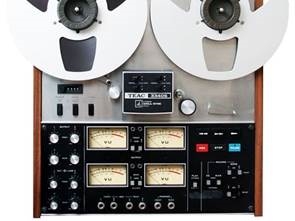
Introduction
Congratulations. You now own a TEAC 3340S 4-Channel Simul-Sync Tape Deck the second generation of TEAC's famous Creator series. Owning a TEAC 3340S is like having a recording studio at your command. It gives you four separate channels in one direction on which signals from eight different sources may be recorded simultaneously or one channel at a time - synchronously. Independent microphone and line inputs and outputs, each with their own level controls, provide virtually unlimited blending and mixing options. The sonic effects at your command are endless-and limited only by your imagination.
Developed and manufactured by TEAC Corporation, the Leaders in tape recording technology, the TEAC 3340S will give you years of recording and listening pleasure if you continue to give to it the care and attention this deck received during its creation. To this end, we urge you to carefully read and use the contents of this Instruction Manual. With a minimum of regular preventive maintenance and a respect for its limitations and capabilities, you will continue to enjoy the thrill of using and owning the TEAC 3340S.
OPERATIONAL LIMITATIONS

The TEAC 3340S is very well constructed and adaptable to a wide range of conditions. Nevertheless, it has certain limits to be considered as do all electronic devices. To prolong the life of your new deck, consider the following factors when you install and operate the 3340S.
Mounting position
This deck may be used in either the upright or horizontal positions. The upright position is preferred for it offers more efficient ventilation. For horizontal operation, always attach and use the rubber mounting feet on the back edges of the deck for protection of the Remote/Timer Control Dummy Plug.
Constant high temperature locations
Do not operate this unit near heating appliances or on top of an amplifier where amplifier heat would contribute to a rise in the deck's operating temperature. Do not place the unit where it will be exposed to direct summer sunlight. Temperature extremes will not only cause degradation of sound quality, but will also shorten the useful operating life of the unit. Avoid temperatures higher than 100°F.
Extremely low temperature locations
In low temperature locations, the lubricants will harden and satisfactory operation cannot be expected. Operation will be sluggish and an overload may be placed on the drive motors. Avoid temperatures lower than 40°F.
High humidity locations
High humidity will hasten corrosion and possible fungus growth on the printed circuit boards, thus shortening equipment life and performance.
Dust environments
Your TEAC deck is a precision-built machine and as such should be protected from dust. Operation in a dusty atmosphere will result in excessive bearing and tape head wear tape deck should be kept dust-free.
Fluctuating supply voltage
Should you be in an area where fluctuation in the AC line voltage is severe, the use of a voltage controller may be advisable.
- Photographs and/or illustrations may differ slightly from the appearance of your deck when production design improvements are incorporated.
Location of Features and Controls

- Quick- Lock Reel Holders Firmly hold tape reels to the reel tables.
- Reel Tables Provide a platform for the tape reels
- Tape Tension Arm Acts as a mechanical filter with the Tape Guide Post (4) to maintain proper tape tension.
- Tape Guide Post
- Index Counter Indicate relative location of selections on the tape
- Index Counter Reset button Restores Counter digits to "0000"
- POWER switch Depress to apply power, VU Meter lamps will illuminate as selected by the PLAY switch 17. Push again for OFF.
- REEL Size selector switch Establishes proper back tension and reel torque for LARGE (10 1/2") of SMALL (7") reel sizes.
- SPEED selector switch Depress for the LOW speed of 7 1/2 ips (19 cm/s), release for the HIGH speed of 15 ips (38 cm/s).
- OUTPUT Level controls Four, independent controls for regulating the level to the OUTPUT jacks 31.
- MIC/LINE Input Level controls Dual concentric Knobs controlling (the recording input level. The front, center section of each knob is for MIC inputs. The rear, outer section of each knob is tor LINE inputs
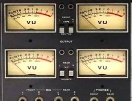
- VU Meters Provide individual channel monitoring during recording or playback. VU Meter placement corresponds with the OUTPUT and Input Level controls and with standard mic and speaker geometry for 4 channel recording and playback.
- FRONT-MIC-REAR Microphone Input Jack For standard microphones, high impedance (600 to 10000 ohms).
- OUTPUT Monitor selector switches Select TAPE or SOURCE monitor for each channel which will be displayed on the VU meter and heard at the PHONES and OUTPUT jacks.
- Record indicator lights Illuminate when the associated channel is in the Record Mode.
- PHONES jacks (FRONT — REAR) Jacks for 8 ohm stereo headphones, one for the FRONT two channels (1 & 3), another for the REAR two channels (2 & 4).
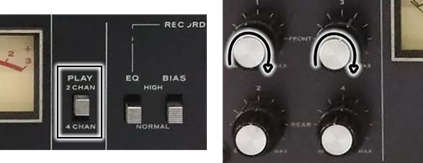
- PLAY (2CHAN/4CHAN) switch Selects either 2-channel (stereo) or 4 channel operation during playback and recording. Switch must be in 4 CHAN position for 4 channel recording. Lower two (REAR) VUE meter lamps extinguish when 2 CHAN is selected.
- RECORD ~ EQ switch Selects proper equalization for Low Noise/High Output (HIGH), or conventional tapes (NORMAL).
- 19 RECORD ~ BIAS switch Selects proper bias current for Low Noise/High Output (HIGH) or conventional tapes (NORMAL).
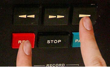
- RECORD MODE switches
Select which channel or channels will be recorded - Control Center Includes 6 buttons which provide control of the tape transport motion and record activation
- Shut-Off Arm Removes electrical power from the transport section if the tape breaks or ends. Also provides tape guidance.
- Pinch Roller Applies proper pressure for the tape to be driven by the capstan. Engaged only in the Play and Record modes
- Capstan Drives the tape at a constant speed in the Play or Record modes. Not engaged with the Pinch Roller during Fast Forward or Rewind modes, but rotation continues until electrical power is removed from the transport.
- NORMAL/SIMUL-SYNC switches In the NORMAL position, the TAPE monitor function is performed by the Playback head. In the SIMUL-SYNC position, the function is switched to the record head lo permit synchronization with material being recorded on another channel. Always use the NORMAL position during regular Playback operation.
- Head Housing Protects the heads and SIMUL-SYNC switches from dust and damage.
- GND connection For connecting a grounding wire between components or to earth ground if necessary to eliminate electrical hum.
- FUSE holder Contains a 2 amp fuse for overload protection.
- AC POWER IN Male Sacket Connect the electric power cord here.
- REMOTE CONTROL RCO-120/TIMER CONTROL RC-320 Dummy Plug Unless one of the two optional accessories is connected here, this Dummy Plug must be inserted to permit proper operation of the tape transport.
- OUTPUT jacksConnect to the Discrete inputs of a 4 channel amplifier or two 2-chaniel amplifiers. Notice that ihe channel designation corresponds with the VU
- LINE IN jacks Line inputs for recording are connected to these four pin cord jacks.
Basic Connection and Speaker Placement
4-Track / 4-Channel Connections

The 3340S is a discrete, 4-channel stereo tape deck. For full utilization of all four channels, it must be used with two separate 2-channel amplifiers or (preferably) with one 4-channel stereo amplifier having separate, discrete inputs and outputs for each of the four channels. To maintain compatibility with standard 2 Channel stereo tapes, the channels are numbered to correspond with the tracks on the tape. They are further designated "Front" and "Rear" to identify them with normal microphone and speaker placement.
Thus channel 1 is FRONT, L1 channel; channel 2 is REAR, L2; channel 3 is FRONT, R3; and channel 4 is REAR, L4. The LINE IN and OUTPUT jacks of the 3340S should be connected to the corresponding designations on the panel of the 4-channel amplifier.

If your 4-channel amplifier does not have a discrete output for 4-channel tape recorders with 4 separate jacks to correspond with the LINE IN jacks on the 3340S, discrete 4-channel Recording and Playback from the deck cannot be expected.
4-Track / 2-Channel Connections

If you wish to use the 3340S as a conventional, 2-channel stereo tape deck, use the FRONT connections only (L1 and R3). Remember to place the PLAY switch on the front of the deck to the 2CHAN position and leave it there.
Basic Operation of the TEAC 3340S
Transport Controls
Certain operations are basic to tape deck operation and are referred to throughout this manual in a few words when they actually involve a certain level of familiarity with the tape transport operation. Connect only the AC power cord and use a reel of blank (unrecorded) tape and an empty reel.
Quik-Lok Reel Holders

- Loosen the reel shaft tip fully CCW (counter-clockwise).
- Align the outer 3 index tabs (Ref. 2) and the inner 3 index tabs (Ref. 3). This is done by turning the upper tab section (Ref. 2) slightly CCW to place the tabs in a straight line between the two sections.
- Using both hands, grasp a reel and its center hole partially over the reel shaft tip (Ref. 1). Then gently rotate the reel CCW while sliding the reel fully onto the turntable. When the outer 3 index tabs (Ref. 2) are fully visible above the reel, you may proceed to step (d).
- Carefully rotate the outer tab section (Ret. 2) clockwise until it stops (approximately 60 degrees or 1/6 of a revolution. Then turn the reel shaft tip clockwise approximately 3 revolutions so it is fingertip (Tape winds rapidly onto left reel) tight. The outer index tabs must be about midway between the corresponding slots on the reel.
 NOTE: The tape must leave the left side of the reel.
If large-center (NAB 10-1/2") metal reels are to be used, insert the plastic Reel Adapters into the center of the metal reels before placing them on the reel tables. Also place the Reel Heights Adapter sheets on to the Reel Tables. These inserts and sheets are included with the Standard Accessories packet accompanying your deck. Always use a reel of the same type and size on the right take-up reel table. Both reels should be of the same hub (Establishes Record mode without diameter, material and outside diameter to insure proper braking starting tape movement, RECORD and tension.
Threading the tape

- Carefully unreal (pull out) approximately 30 inches (75 cm) of tape from the supply reel. Thread this tape in the following manner: Over the left Tension Arm, under the Guide Post, under and through the Head Housing, between the Pinch Roller and Capstan, under and around the right Shut-Off Arm, then onto the take up reel.
- Secure the end of the tape to the take up reel by holding the end of the tape in the slot while rotating the wheel several times counter-clockwise (CCW)
- Continue rotating the take up reel until the tape is no longer loose. Correct tension will raise the Shut-Off Arm from the 3 o'clock position to the 10 o'clock position.
Forward Payback
(Tape moves from left to right)
Fast Forward

(Tape winds rapidly onto right reel)
Fast Rewind
(Tape winds rapidly onto left reel)
Record

(Tape is recorded, MODE switch must be ON.)
Record Pause
(Establishes Record mode without starting tape movement, RECORD MODE switches must be ON, both lights illuminate.)
Pause
(Stops tape motion; when recording retains mode and light illuminates; during Playback acts as a STOP button.)
Stop

(Tape motion ceases, mode is released.)
Playback Operation
Preliminary Settings

- Thread the tape.
- Confirm all Simul-Sync switches in the NORMAL position.
- Reset the Index Counter for "0000"
- Set the following switches as indicated:
- REEL Size Selector switch to match the reels.
- Speed Selector switch to match the speed used when the tape was recorded.
- All Level controls (OUTPUT, MIC, LINE) to MIN (counter-clockwise)
- All OUTPUT Selector switches for TAPE monitoring.
- PLAY switch for 4 CHAN operation.
- RECORD - EQ and BIAS switches have no effect during playback.
- RECORD - MODE switches all OFF
- Verify the correct connections between all components.
- Prepare the 4-Channei Amplifier or integrated receiver for Discrete 4-Channel playback according to its manual of instructions.
Operation
- Depress the POWER switch to ON.
![]()
- Rotate the right-side wheel clockwise by hand to remove the slack (looseness) from the tape, raising the Shut-off Arm.
![]()
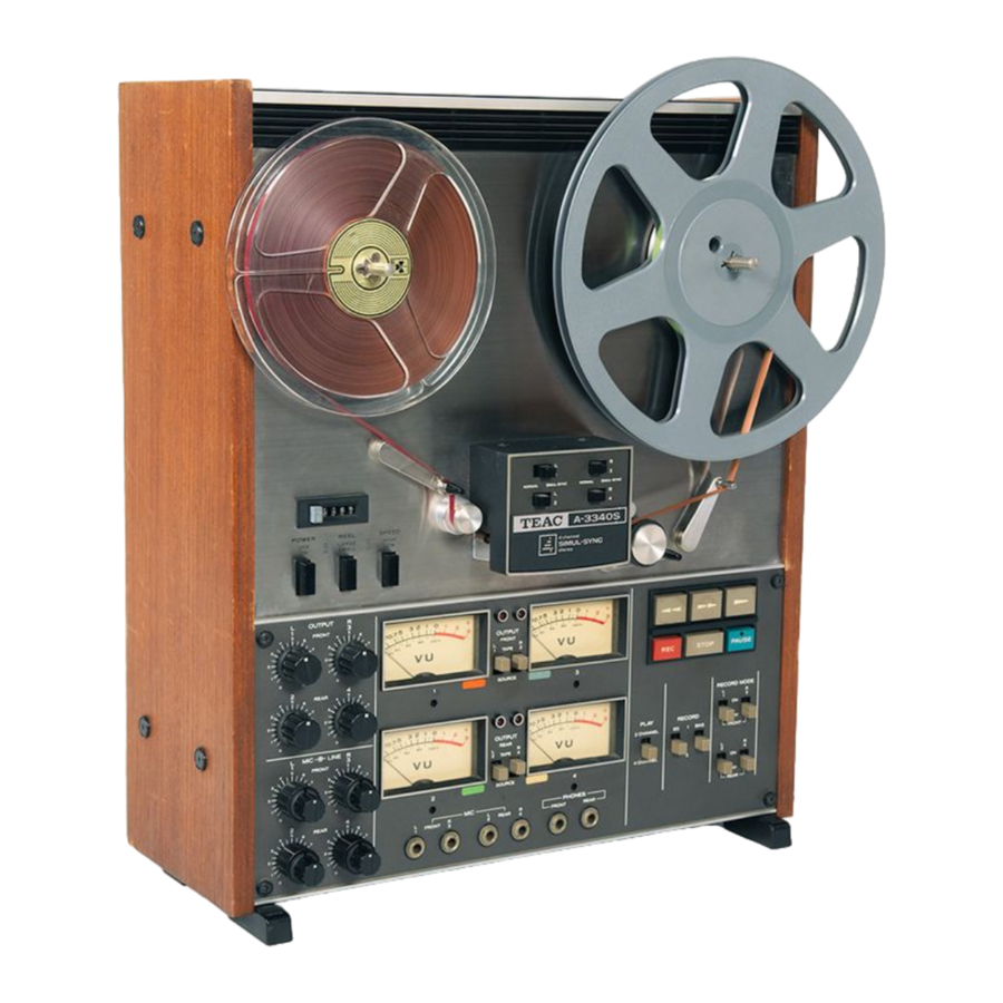
- Depress the
![]() button for Playback to begin.
button for Playback to begin.
![]()
- Adjust the OUTPUT Level Controls individually for each channel while observing the related VU Level Meter. The loudest passages of music should reach but not exceed a 0 VU indication.
![]()
- Control the listening level by the Volume Controls on your 4-Channel Stereo Amplifier.
- After completing all audio adjustments on the deck and the amplifier (tone, balance, filter, etc.) you may rewind the tape to "0000" and listen again from the beginning.

 button for Playback to begin.
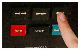
Alternate Playback Procedures
The 3340S will play back almost any kind of recorded 1/4 in tapes, including 4-track/4-channel, 4-track/2-channel, 4Track monophonic, 2-track stereo, 2-track monophonic and Full track monophonic. Use the basic Playback Procedures (previous page) but modify it according to the instructions in the chart below.
Please note these points regarding the following chart:
- Keep the OUTPUT Level controls to MIN unless the O marks indicate they are to be used.
- Keep the OUTPUT Selector switches to SOURCE unless the T indicates they are to be set for TAPE.
- Monophonic recordings will be heard only from one Front speaker, the side depending upon the track being played.
- When there is more than one step numbered in the STEP column, you must change the full reel of tape from the right to the left side before beginning the next step.
- two-channel stereo amplifier is satisfactory for all except 4 -Track/4 -Channel playback.
| PRE-RECORDED TAPE |  |  | OUTPUT LEVEL CONTROL | OUTPUT SWITCH | PLAY SWITCH | HEAD PHONE | VU METER | ||||||||||||||
| F | R | F | R | F | R | ||||||||||||||||
| 1 | 3 | 2 | 4 | 1 | 3 | 2 | 4 | 2CHAN | 4CHAN | F | R | 1 | 3 | 2 | 4 | ||||||
| 4 TRACK 4 CHANNEL | 1 | 1.3 2.4 | O | O | O | O | T | T | T | T | O | O | O | O | O | O | O | ||||
| 4 TRACK 2 CHANNEL | 1 | 1.3 | O | O | T | T | O | O | O | O | |||||||||||
| 2 | 2.4 | O | O | T | T | O | O | O | O | ||||||||||||
| 4 TRACK MONOPHONIC | 1 | 1 | O | T | O | O | O | ||||||||||||||
| 2 | 4 | O | T | O | O | O | |||||||||||||||
| 3 | 3 | O | T | O | O | O | |||||||||||||||
| 4 | 2 | O | T | O | O | O | |||||||||||||||
| 2 TRACK (HALF TRACK) | 1 | 1 | O | T | O | O | O | ||||||||||||||
| 2 | 2 | O | T | O | O | O | |||||||||||||||
| 2 TRACK 2 CHANNEL | 1 | 1.2 | O | O | T | T | O | O | O | O | |||||||||||
| FULL TRACK | 1 | 1 | O | O | T | T | O | O | O | O | |||||||||||
Recording Operation
Preliminary Settings

- Thread the tape.
- Confirm all Simul-Sync switches to the NORMAL position
- Reset the Index Counter for "0000".
- Set the following switches as indicated:
- REEL Size Selector switch to match the reels.
- SPEED Selector switch to the desired speed.
- All MIC and LINE Input Level controls to MIN.
- All OUTPUT Level Controls to the 2 o'clock position.
- All OUTPUT Selector switches for SOURCE Monitoring.
- PLAY Switch for 4CHAN operation
- RECORD-EQ and BIAS switches according to the tape type. HIGH for Low Noise/High Output tape. NORMAL for conventional tape
- RECORD - MODE switches all ON.
- Verify the correct connections with your LINE IN source. Check the positioning of your microphones (as appropriate).
- Prepare the 4-Channel amplifier or integrated receiver for a discrete 4-channel recording output according to its manual of instructions.
- Use headphones for monitoring a live recording to prevent feedback squeals or howls.
Operation
- Depress the POWER switch to ON
- Rotate the right-side reel clockwise by hand to remove any slack (looseness) from the tape, and to raise the shut-off Arm.

- Start the Line or Microphone source program. Play or perform the loudest passages which will be encountered in the recording.
- At the loudest parts, increase the MIC or LINE Input Level controls while watching the VU Meter indications one channel at a time. Set the controls so the peak signals reach but do not exceed 0 VU. Repeat this procedure for each channel and leave the controls at their established settings.

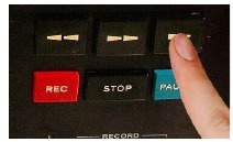
- Depress the REC and
![]() buttons, holding them down until the red Record Indicator lamps illuminate and tape travel begins.
buttons, holding them down until the red Record Indicator lamps illuminate and tape travel begins. - While recording, switch the OUTPUT Selector switches to TAPE and adjust the OUTPUT Level Controls one at a time until each channel indicates approximately the same between SOURCE and TAPE monitoring positions. Leave the switches in the TAPE position unless special recording techniques apply.

- Use the PAUSE control for momentary interruptions. The STOP button will disengage the Recording mode when you finish recording.


 buttons, holding them down until the red Record Indicator lamps illuminate and tape travel begins.
Additional Recording Procedures

The 3340S can be used as a conventional 4-track/2-channel tape deck. For that purpose, place the PLAY switch to 2CHAN and record using channels 1 and 3 (FRONT) only. The RECORD - MODE switches for channels 2 and 4 should be left OFF, and the OUTPUT Level controls and MIC/LINE Input controls for channels 2 and 4 reduced to MIN. The recording procedures should be the same as given under "4 Channel Stereo Recording Procedures" except you will delete all references to channels 2 and 4, as explained above.
The chart below outlines basic switch and control functions for the various recording formats possible with the 3340S. Use it in conjunction with the basic procedures and information given here and elsewhere. For more complete procedures on Simul-Sync recording, see the section following this chart.
Note the following points:
- Keep the OUTPUT, MIC and LINE Level Controls to MIN unless the chart indicates their use.
- A two-channel stereo source is satisfactory for all except 4-track/4 -channel simultaneous recording.
- Use headphones when recording with microphones to prevent feedback squeals or howls in the recording.
- When there is more than one step numbered in the STEP column below, you must change the full reel of tape from the right to the left Red Table between steps.
| BLANK TAPE |  |  | LEVEL CONTROLS | SWITCHES | VU METER | HEAD PHONE | ||||||||||||||||||||||||||||
| MIC | LINE | OUTPUT | RECORD MODE | OUTPUT | PLAY CHANNEL | |||||||||||||||||||||||||||||
| F | R | F | R | F | R | SIMUL-SYNC | F | R | F | R | F | R | ||||||||||||||||||||||
| 1 | 3 | 2 | 4 | 1 | 3 | 2 | 4 | 1 | 3 | 2 | 4 | 1 | 3 | 2 | 4 | 1 | 3 | 2 | 4 | 1 | 3 | 2 | 4 | 2 CHAN | 4 CHAN | 1 | 3 | 2 | 4 | F | R | |||
| 4 TRACK 4 CHANNEL | 1 | 1·3 2·4 | O | O | O | O | O | O | O | O | O | O | O | O | N | N | N | N | ON | ON | ON | ON | S/T | S/T | S/T | S/T | O | O | O | O | O | O | O | |
| 4 TRACK 2 CHANNEL | 1 | 1·3 | O | O | O | O | O | O | N | N | ON | ON | OFF | OFF | S/T | S/T | O | O | O | O | ||||||||||||||
| 2 | 4·2 | O | O | O | O | O | O | N | N | ON | ON | OFF | OFF | S/T | S/T | O | O | O | O | |||||||||||||||
| 4 TRACK MONOPHONIC | 1 | 1 | O | O | O | N | ON | OFF | OFF | OFF | S/T | O | O | O | ||||||||||||||||||||
| 2 | 4 | O | O | O | N | ON | OFF | OFF | OFF | S/T | O | O | O | |||||||||||||||||||||
| 3 | 3 | O | O | O | N | OFF | ON | OFF | OFF | S/T | O | O | O | |||||||||||||||||||||
| 4 | 2 | O | O | O | N | OFF | ON | OFF | OFF | S/T | O | O | O | |||||||||||||||||||||
| SIMUL SYNC (4TRACK) | 1 | 1 | O | O | O | N | ON | OFF | OFF | OFF | S/T | O | O | O | ||||||||||||||||||||
| 2 | 2 | O | O | O | SIM UL | N | OFF | OFF | ON | OFF | T | S | O | O | O | O | ||||||||||||||||||
| 3 | 3 | O | O | O | O | O | SIM UL | N | SIM UL | OFF | ON | OFF | OFF | T | S | T | O | O | O | O | O or O | |||||||||||||
| 4 | 4 | O | O | O | O | O | O | SIM UL | SIM UL | SIM UL | N | OFF | OFF | OFF | ON | T | T | T | S | O | O | O | O | O | O or O | |||||||||
4 track, 4-channel Simul-Sync Recording
Discrete, separate channels are recorded on each of the 4 tracks in the same direction and synchronized as in 2-channel stereo recordings. From a 4-channel source, the tracks are recorded simultaneously. With the Simul-Sync function, they may be recorded separately and synchronized at the time of recording.

4-Channel Simul-Sync Recording Procedures

Preliminary Settings
- Thread the tape.
- Confirm all Simul-Sync switches to the NORMAL position
- Reset the Index Counter for "0000".
- Set the following controls as indicated:
- REEL Size Selector switch to match the reels.
- SPEED Selector switch to the desired speed.
- All MIC and LINE Input Level controls to MIN.
- Channel L1 OUTPUT Level control to the 2 o'clock position.
- All OUTPUT Selector switches for SOURCE Monitoring.
- PLAY Switch for 4CHAN operation.
- RECORD-EQ and BIAS switches according to the tape type, HIGH for Low Noise/High Output tape or NORMAL for conventional tape
- RECORD - MODE switches all OFF, except channel L1 = ON.
- Verify the correct connections with your LINE IN source and/or check the positioning of your microphones (as appropriate).
- Connect microphone to the MIC Input=1.
- Use headphones connected to the FRONT PHONES jack for live recording monitor.
Operation
- Depress the POWER switch to ON. Rotate the right-side reel clockwise by hand to remove any slack (looseness) from the tape, and to raise the shut-off Arm.
- Set the recording level (before beginning recording) by playing or performing the loudest portions of the program. Increase the MIC or LINE Input Level control L1 for a peak reading of 0 VU.
- Begin recording by depressing the REC and
![]() buttons at the same time, holding until the red Record Indicator light illuminates for channel L1.
buttons at the same time, holding until the red Record Indicator light illuminates for channel L1. - Rewind the tape to "0000", depress the
![]() button and review the first recording. If satisfactory rewind again and proceed to step 5.
button and review the first recording. If satisfactory rewind again and proceed to step 5. - Make the following settings:
- Output level controls # 1 and # 2 to 2 o'clock position.
- Simul-Sync switch # 1 to Simul-Sync position.
- RECORD – MODE switch #1-OFF, #2-ON
- OUTPUT Selector switch #1-Tape, #2-SOURCE


- Leave headphones connected to FRONT; change the microphone to MIC jack #2.
- Reduce the MIC Input Level Control #1 to MIN; adjust the MIC Input Level control #2 for a VU Meter indication of 0 VU on the loudest peaks of a test session.

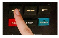
- Standby to perform; depress the
![]() and REC buttons to start the deck; monitor the Simul-Sync output from track One while recording a synchronized program on track Two.
and REC buttons to start the deck; monitor the Simul-Sync output from track One while recording a synchronized program on track Two.
![]()
- Repeat the changes and procedures as above and in the chart to make successive recordings on the remaining tracks. You may record one, two, or three tracks at a time while synchronizing them with an earlier recording. Note, however, the following points:
- When SIMUL-SYNC is selected, that Channel will not record.
- Never change the Simul-Sync switch function while recording, for the surge currents could strongly magnetize the record head.
- The original recording will remain on the first track.

Explanation of the Features and Controls
RECORD MODE switches

There is a separate MODE switch for each channel and this switch must be ON to record on that channel. Separate recording MODE switches are not only a safety feature, but they also make it possible to perform selective recording on any channel you might select. Keep all switches OFF during Playback and place a MODE switch ON only if you wish to record on that channel.
When the PLAY switch is in 2CHAN, you can record channels L1 and R3 only, regardless of the position of a MODE switch for channels L2 and R4. Similarly, a safety feature in the SIMULSYNC switches prevents recording if a channel has SIMULSYNC monitoring selected.
You may go directly from Playback to Record mode if the MODE switch is on during playback operation. Without depressing the STOP button, while the tape is in motion, hold the REC button while you press the Play button. The red Record Indicator lamp will illuminate. This is called a "running slice" or "punch-in recording".
REEL Size selector switch

The REEL Size selector switch must be set to the proper position corresponding with the size of the reel: LARGE for 10-1/2" reels, SMALL for 7" reels. This switch prepares the transport for the proper back tension, take-up torque and braking which differ between the reel sizes. Improper REEL Size selection will result in excess tape tension and possibly tape breakage for 7" reels. With 10-1/2" reels, SMALL size selection will cause recording dropouts. With either error, the tape-to-head pressure will be incorrect.
OUTPUT selector switches

The four switches located between the VU Meters are called the OUTPUT Selector switches for they select which Output will be heard at the OUTPUT jacks on the rear of the deck. They also select which signal will be displayed on the VU Meters. In both cases, the selection is between TAPE and SOURCE. TAPE refers to the signal which has already been recorded onto the tape. This signal is obtained from the Playback head when the Simul-Sync switch is NORMAL, and from the Record Head in SIMUL-SYNC. The SOURCE position obtains the selected signal from the Recording Amplifier at the point in the circuit before it is applied to the recording heads. Thus it gives an accurate indication of the strength of the signal being recorded onto the tape.
You will notice that each channel has its own OUTPUT switch, which is an advantage over conventional 2-Channel decks, for you may select the desired type of monitor, TAPE or SOURCE independently for each channel.
Tape monitoring is important while recording to verify the quality of your recording. While source monitor will tell you exactly what is going into the recorder, only tape monitoring will tell you just exactly what you have recorded. Lt will detect any blank spots on the tape; detect wow or flutter in the deck (if maintenance is required); warn you if the heads have become dirty or magnetized; advise you if the heads are out of alignment; and generally, confirm for you that you are making a high-quality recording.
Always set the OUTPUT switch to SOURCE when you make the initial recording level settings with the MIC or LINE input level controls. The VU Meters will then display the Input signal, and they will be controlled by Input controls. Once the level has been set, select the TAPE OUTPUT position and adjust the OUTPUT Level controls to obtain the same reading. Alternate between the SOURCE and TAPE position to compare the quality of the sound through headphones or your stereo speakers.
When using the Simul-Sync function there are two exceptions to the above. First, the basic channel that is using the SIMUL-SYNC switch position must have the TAPE monitor position selected on its OUTPUT switch. This is because you are not recording on that channel but you, wish to hear that channel as in Playback. Second, for perfect synchronization, maintain the SOURCE position on the remainng channels' OUTPUT switches. This will avoid the slight time lag inherent with normal TAPE monitoring.
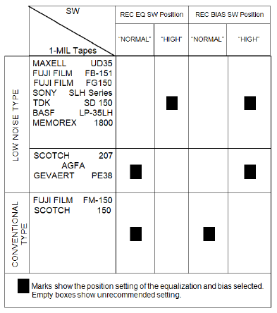
RECORD BIAS and EQ switches

Tape recording technology was recently challenged by the improved tapes developed by recording tape manufacturers. These tapes offered improved performance from tape decks, but this better performance was only possible by changing the internal electronic characteristics of the tape deck. The TEAC 3340S has special circuitry for these new low noise/high output tapes as well as conventional circuitry for the regular tapes. The proper circuitry is selected by the RECORD-BIAS and EQ switches.
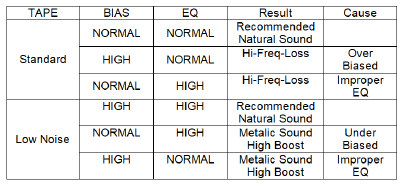
BIAS Switching
The HIGH position is preferred for most of the low noise/high output types of tapes. These tapes sell under a variety of different names, but can be recognized as an improved or advanced type of tape. The NORMAL position is ideal for conventional kinds of tape, which still give excellent recording results with the TEAC 3340S.Some of the newer kinds of tape are designed for use with the lower NORMAL Bias levels. If you are in doubt as to which level to use, your dealer can tell you.
EQ Switching
The EQ switch controls equalization for recording. Like the BIAS switch, that has no effect during Playback operation. Generally, you should place this switch in HIGH if the BIAS switch is in HIGH. These switches are set to match the type of tape. HIGH for low noise/high output, NORMAL for conventional tape. You may, through experimentation, find a particular brand which gives better results using HIGH Bias and NORMAL Equalization.
Tape SPEED (High-Low) selector switch
 selector switch")
Control of the tape speed is provided for the two common recording speeds: 15 ips (38 cm/s) and 7-1/2 ips (19 cm/s). The slower speed will give you twice the time from a reel of tape as the faster, but with a very slight decrease in performance as indicated in the specifications.
The SPEED selector switch selects 7-1 /2 ips when depressed to the (  ) position. A second push releases it back to the 15 ips speed (
  ).
).
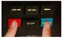
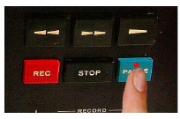
PAUSE Control button operation

Recording is greatly simplified by using the PAUSE button rather than the STOP button when you wish to temporarily halt the tape transport. The PAUSE mode is engaged by depressing the PAUSE button while recording to keep the deck's recording circuits engaged. Recording is instantly restored by merely pushing the ![]() (Forward Play) button.
(Forward Play) button.
Use the PAUSE button
- to eliminate commercials when recording from the radio;
- to eliminate interruptions in the recording during live recording or those caused by changing discs;
- for keeping switch noises or needle clicks out of the recording;
- anytime you wish to momentarily stop recording.
If the STOP button is used rather than the PAUSE button, you must depress both the REC and the ![]() (Forward Play) buttons to resume recording. During tape playback, the PAUSE button functions only to stop the transport in rhe same manner as the STOP button.
(Forward Play) buttons to resume recording. During tape playback, the PAUSE button functions only to stop the transport in rhe same manner as the STOP button.
PLAY Channel selector switch

To simplify converting the 3340S from 4-Channel to 2-Channel operation, a PLAY switch has been incorporated which disconnects tracks 2 and 4 when placed in the 2- CHAN position. In that position, the VU Meter lights in the REAR VU Meters are extinguished and the RECORD MODE switches for the REAR Channels become inoperative. Also, in the 2CHAN condition, the 3340S may be connected to a regular 2-Channel Stereo Amplifier through channels 1 and 3 for normal 2-channel operation. The 4CHAN position restores the deck to the 4-Channel/4- Track discrete condition.
Simul-Sync switches

The Simul-Sync switches should always be left in the NORMAL position unless you wish to synchronize the recording of a new track with one already recorded. These switches effectively convert the selected Record head into a playback monitor head when switched to SIMUL-SYNC if the corresponding OUTPUT selector switch is positioned to TAPE.
When the SIMUL-SYNC position is selected, that channel cannot be recorded as a safety device prevents recording on that channel. The Simul-Sync function is only for monitoring to enable track synchronization. Therefore, the sound available from the Simul-Sync head will not be as rich and pure as that from the Playback monitor head. Do not judge the quality of the sound on the tape by the sound from the Simul-Sync monitor function.

Level Setting
Correct level setting of the MIC and LINE Input Controls will assure full frequency response, maximum dynamic range, minimum amount of tape noise and the least possible distortion in your recorded tape. This is based upon the nature of magnetic recording tape which has a useable recording range as shown in the chart below.
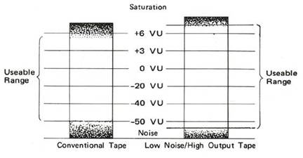
When the input level (an audio signal of a specified voltage) is very low or weak, it must compete with the hiss and noise always present at the same low level on the tape. Stronger input levels are recorded above this tape noise and tend to cover or "mask" it so you hear only the desired sound during playback. If the input level is too high, it enters the region shown at the top of the chart, which represents the limits of the tape. This limit says that no matter how much stronger you record, the tape cannot accept and return the same strength of signal. The result is known as "saturation distortion", and is heard as a garbled or harsh sound. The dynamic range available is found between this distortion at the high end and the noise at the low end. As the chart also shows, there is a difference between recording tapes. The tape on the left is representative of conventional or normal recording tape. To the right is the improved kind of low noise/high output tape.
Input Level Controls (MIC and LINE) are used to match the strength of the input signal to the requirements of the tape. If the input signal is a little too strong, these controls must be adjusted to reduce it to prevent distortion. If the signal is a little too weak, the controls must be set to increase the preamplification for raising the signal above the tape's noise level. Of these two limits, the distortion caused by high level inputs is used as a reference for setting the controls. Generally speaking, the shaded area at the upper (right side) of the VU meters' scale indicates that distortion levels are being approached. This area begins at 0 VU. As the ideal is to record the program without distortion of the loud parts or losing the purity on the quieter parts, the recording level must consider both limits.
Setting the Playback Level
- Set the OUTPUT switch to TAPE
- Set the OUTPUT Level control to approximately the 2 o'clock position.
- Begin Playback by depressing the
![]() Button.
Button. - Adjust the OUTPUT Level control so that the loudest passages on the tape indicate 0 VU.

- Make all listening volume adjustments (for loud speaker output) by changing the stereo amplifier's volume controls.
- Further changes to the OUTPUT Level controls are not needed unless the VU Meter pointers greatly exceed the original setting.

Setting the Recording Level
- Begin recording with the MIC and LINE Input Level controls at the 9 o'clock position or below. If the input is only from microphones, keep the LINE controls fully to MIN. If only LINE Inputs are used, keep the MIC controls fully to MIN.
- Gradually raise the level by turning the controls clockwise while observing the Meters. Remember to use the MONITOR switch in the SOURCE position.
- Stop raising the level when each channel indicates slightly over 0 VU on the loudest passages.
- If there is more than 1 or 2 VU difference between channels, increase the low-reading channel to the same level. Balance the channels to the same peak reference levels.
- Generally speaking, you should not re-set the level unless the Meters indicate too low or too high:
- After changing records or sources, the level should be reset.
- During a selection, if the meter goes excessively into the red area, the level should be reset and the recording should be restarted using the new level setting.
- While monitoring off the tape during recording, the level should be raised if soft, quieter passages are covered by tape hiss.
- If vou must reduce or change the level while recording, move the controls slowly and gradually to prevent sudden changes in the recording. These changes would be heard as an annoying jump or drop during playback
- These three things must be avoided:
- Do not let the meter pointers bounce or stick against the peg on the right side.
- Tape saturation distortion will be unpleasant to the listeners.
- Too low a level will be unpleasantly noisy.
General Recording Information
Tracks, Channels, and Compatibility
Sound recordings are made in a strip on the magnetic surface of a recording tape. This magnetized strip is called the "Track". The full tape width divided by two is called a "2" track recording, and the full tape width divided into quarters is called a "4" track recording.
"2" track recording
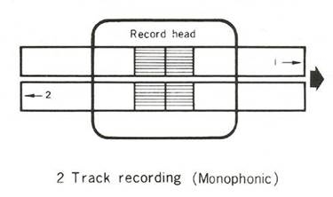
2-track recording is mainly employed in radio stations and professional recording studios for stereo recording. In this case both tracks are recorded simultaneously and in the same direction. 2-track recording in the home is usually done one track at a time and is played back monophonically.
"4" track recording (Stereophonic )
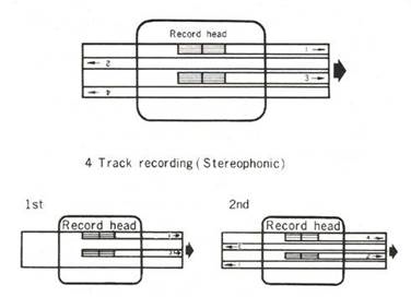
In this mode two tracks are recorded simultaneously. On the first pass of the tape, tacks = 1 and = 3, are recorded. The left and right reels are then interchanged and tracks= 2 and =4 are recorded. The left channel sound will be on tracks= 1 and =4 and the right channel sound will be on tracks= 2 and = 3. Four track recording in stereo is the most widely used recording method today.
"4" track recording (Monophonic)
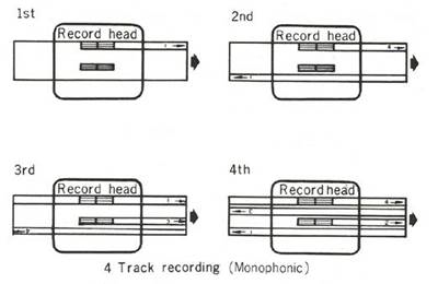
In this mode, each of the four tracks is recorded individually. At the end of the tape the reels are interchanged between left and right and the next track is recorded. The order in which the, tracks are recorded is #1, #4, #3 and lastly #2.
| Playback Sequence | 1st | 2nd | 3rd | 4th |
| Track Used | 1 | 4 | 3 | 2 |
| Direction of Tape Run |  |  | | |
| Level control knob | inner L | inner L | outer R | outer R |
| Level meter pointer | left | left | right | right |
"4" track recording (4-Channel Stereo)

In this mode all 4 tracks are recorded simultaneously from left to right. Each track contains discrete but synchronized program material. A 4 section playback head is utilized and 4 amplifiers and 4 speaker systems are required. Tracks 1 and 3 are called "Front" left and right respectively, tracks 2 and 4 are called "Rear" left and right. Front and rear correspond to the usual speaker placement in the room in relative to the position of the audience. 4-track 4-channel tapes must be played on a player incorporating a 4-track head and four independent playback amplifiers.
Playback Compatibility
A four-track stereo tape deck can playback both 4 channel and 2 channel tapes and from the point of compatibility, has the widest possible range of utilization. When playing a 4-channel stereo tape on a 2-channel deck, tracks #2 and #4 cannot be heard.
The tape
The length of tape recording time is determined by the reel diameter and the thickness of the base material. The use of a 1 or 1-1 /2 mil base tape is recommended for 4 track high fidelity recording. Polyester base tape is preferred for use in humid or extremely dry areas.
The recording time indicated in the chart to the right is for one single pass of the tape. The total recording time will be either two or four times that indicated, depending upon the method of recording.
Good quality tape wound on correct reel
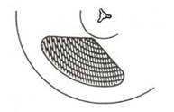
Tape condition can be judged by the appearance when wound on the reel and viewed from the side.
- Is it neatly wound?
- Are there steps or irregularities in the winding?
- Is the color of the base uniform as seen from the side?
- Is the tape edge smooth?
Fungus indicates old tape stored for a length of time under high humidity. Sections where the splicing tape has been applied are especially prone to support fungus growth.
Creases extending from the center positively indicate uneven stretching. This is caused by differences in temperature and humidity.
| 10 1/2" reel | |||
| Base | Tape Length | Recording time | |
| 7½ ips | 15 ips | ||
| l½ mil | 2,400 feet | 60 min. | 30 min. |
| 1 mil | 3,600 feet | 90 min. | 45 min. |
| ½ mil | 4,800 feet | 120 min. | 60 min. |
| ½ mil | 7,200 feet | 180 min. | 90 min. |
| 7" reel | |||
| Base | Tape Length | Recording time | |
| 7½ ips | 15 ips | ||
| 1½ mil | 1,200 feet | 30 min. | 15 min. |
| 1 mil | 1,800 feet. | 46 min. | 23 min. |
| ½ mil | 2,400 feet | 60 min. | 30 min. |
| ½ mil | 3,600 feet | 90 min. | 45 min. |
Selecting the tape and reel
For recording, new tape is not necessarily needed. If the tape is of good quality the erase head will erase the previous recording as the new recording is made. However, avoid using tapes whose coating is worn, peeled off or stretched.
If the color of the winding is different throughout the reel, it is an indication that two different types of tape have been spliced in. In some cases, the color may differ according to production lot even for the same type tape, or between opposite sides of the wound tape.
Normal condition reel
The use of a good quality reel is an important point in preventing damage to the tape edge or uneven stretching. Always use reels of the same diameter.
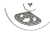
Reels which damage tape

Reels warped in the shape of a bowl will bend the tape, resulting in the so-called uneven stretching, and are sometimes encountered even with new reels.

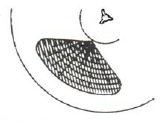
The reel may be warped in a Yo-Yo shape due to tight winding. This will not occur in reels made of hard plastic or whose hub is perfectly fitted.

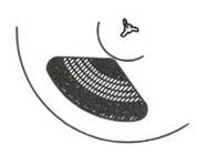
If the hub is not truly perpendicular to the flange, the wound tape will be pressed against the flange resulting in a seaweed form of tape.
Judging tape condition by how it travels

Tapes which snake up and down between the guides and over the heads will inevitably lead to level fluctuation and azimuth misalignment.

Unevenly stretched tape which travels either higher or lower than the true path of the tape will in extreme cases drift off the pinch roller.

Snaky motion of unevenly stretched tape indicated by arrow.
Hang down a length of tape to check straightness

Tape Storage and Handling
Magnetic tape recordings are superior to discs because, with proper care, they can be kept and relayed for many, many years without degradation. During playback, the biggest danger to the recording is a magnetized or dirty point on the deck, such as a head or capstan. Care for the recording and the tape must be continued even after playing it by following these guides:
- Protect the tape from dust
Keep it in the plastic bag and the original carton. - Protect the tape from heat
Do not place it on top of audio components. Store it in a cool room but also avoid freezing temperatures. Keep it out of direct sunlight. - Protect the tape for storage.
Tremendous pressure is built-up on the inner windings of tape. This pressure is acceptable unless you apply additional stress by bending or squeezing the sides of the reels. This problem is increased if the windings are irregular. Frequent starts and stops will cause uneven winding pressure and the tape will be unevenly wound from side to side within the reel. Slight pressures on the sides will then break or crack the edge of the tape. Therefore, always prepare your tapes for longterm storage by rewinding them using the![]() playback operating speed. The
playback operating speed. The ![]() and
and ![]() modes apply somewhat uneven tension to the tape.
modes apply somewhat uneven tension to the tape. - Protect the tape rrom strong magnetic fields
Just as a Bulk Eraser will remove the recorded material, so will a permanent magnet or the voice coil of a speaker destroy your favorite recording. - Protect the tape from humidity
Fungus growths will cause irreparable damage to the tape if stored in damp places. Keep the tape in the original plastic bag, but insure that it is dry before storing.
 and
and  modes apply somewhat uneven tension to the tape.
Editing and Splicing Tape
Editing will destroy or seriously "cut" if any material recorded on the other tracks of the tape. If editing is anticipated, record only on one track of the tape. After editing, material can then be copied onto the other tracks. When attaching blank "leader" tape onto your tapes, follow the same procedures given here for splicing.
Editing tape is a fascinating way to make creative recordings for 1st basic reference track by eliminating and joining different segments of a recording into one pleasing tape. Long silent or boring segments can be removed by proper editing. In fact, as editing is a creative exercise, there is only your imagination and the length of tape to limit the possibilities. Of course, broken tape can also be easily mended by splicing, one of the steps required in editing. The first step is to precisely locate the section of tape to be removed. This can be done by manually cueing the tape.
- Remove the cap from the Pinch Roller.
- Remove the Pinch Roller.
- Hold the right, take-up reel with your hand while you depress the
![]() (Forward Play), button.
(Forward Play), button. - Move the tape back and forth by manipulating the reels until the precise point for editing is positioned at the Forward Play tape head.
- Mark the spot on the tape. Repeat this procedure for the end of the selection to be edited.
Next, use an Editing Block or a pair of scissors (demagnetized) to cut the tape at the places marked.
Finally, the splicing is to be done. A Tape Splicer is preferred, but a pair of scissors that have been demagnetized will be satisfactory. Before you proceed, have some commercially available Splicing Tape available. Never use Cellophane - (Scotch Brand) tape, for that adhesive will spread and contaminate your heads.

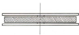
- Overlap the ends to be spliced by approximately 1/2 inch and align them carefully.
- Cut through the center off the overlapped area at a 45 to 60 degree angle.
- Butt the slanted ends of the cut tape together. Use a straight edge or ruler to assure a perfectly straight alignment.
- Apply splicing tape to the shiny base side of the tape as shown in diagram #2. Note that splicing tape goes perpendicular to the recording tape.
- Place the spliced connection on a hard surface and rub the splicing tape briskly with your fingernail or other hard smooth object. This is to assure a firm adherence to the splicing tape.
- Trim off the excess splicing tape as shown in Fig. 3-1 and 3-2. Note how to cut slightly into the recording tape to insure complete removal of the excess.
Erasing Recorded Tape

One of the advantages of recording tape over records is that it can be recorded over and over again. This raises the question of how is the previous recording removed. Here are three different ways to erase earlier recorded material.
Simultaneous erasing and recording
As the photo shows, there is an Erase head, located to the left of the Record head in your deck. Its function is to purge the two tracks of all previous recording by means of a strong alternating magnetic field immediately before the tape reaches the Record Head. This is done automatically whenever you record.
Erasing on the deck
You may erase the entire tape two tracks at a time without recording, by rotating the MIC and LINE Level controls fully counterclockwise and/or disconnecting the Input connections. Start the deck in the 4-channel Record Mode and all tracks will be erased.
Bulk Erasure
TEAC's Model E-2 bulk Tape Eraser (or its equivalent) will quickly erase the entire tape in a few seconds. This is the only satisfactory way to erase a previously recorded "2" track or "Full" track tape to prevent undesirable "crosstalk" or chatter from the former material. For complete directions on how to use, consult the instruction supplied with the Bulk Eraser.
Special Recording/Information and Procedures
Recording with Microphones

Live Recording
High Quality recordings begin with high quality microphones. The TEAC 3340S will perform excellent live recording from any high-quality microphones (such as TEAC's MC-201) with impedances from 600 to 10,000 ohms. Low impedance microphone of 150 - 600 ohms will also work satisfactorily.
- Connect the microphones to the MIC Input jacks on the front panel.
- Use headphones for monitoring to prevent feedback from developing whistles or squacks in the recording.
- Select OUTPUT - SOURCE.
- Reduce the LINE Level control to MIN.
- Adjust the MIC Level control for the proper recording level on the VU Meters.

- Other recording procedures are the same as Recording Procedures.
- Use the PAUSE control during interruptions in the recording.

NOTE: Experimentation, experience and extensive study will be required before you can duplicate the accomplishments of a professional studio recording. Microphone selection, placement of the microphones, and the room acoustics must all be considered in addition to recording levels and special techniques.
MIC/LINE Mixing

You may add your commentary to a musical recording, add music background to a live recording, and perform many other interesting recordings, by combining the procedures for Live Recording with Microphones and the standard recording procedures for Line Inputs. Connect the microphones to the MIC Jacks on the front of the deck. Consider these following points while recording.
- The use of headphones is recommended to prevent feedback squeals and whistles.
- Use the SOURCE selection of the OUTPUT switches to simplify synchronization of the MIC and LINE Inputs.
- Adjust the MIC and the LINE Level Controls to balance the relative levels between the separate inputs while keeping the total input level within the limitations indicated by the VU Meters.
- If the Line Input is Dolby-encoded, please note that the MIC Input will not be Dolbyized, thus it will sound unnatural during playback.
TEAC 3340S

Timer Controlled Recording

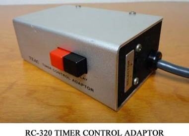
TEAC's optional accessory RC-320 Timer Control Adaptor will work with almost any electrical switching clock timer to start recording on the TEAC 3340S at a preset time. Remove the Dummy Plug from the rear of the deck ro connect the RC-320. Follow the instructions supplied with the RC-320. Remember to make all the preparations for recording and set the recording level before setting the clock timer. You might also want to reduce the speaker volume level on your amplifier. This accessory may be left connected while using normal procedures with the 3440S provided that both buttons on the RC-320 are disengaged (up).
Remote Controlled Recording

TEAC's optional accessory RC-120 Remote Control Adapto r gives you total control over the 3340S transport controls from up to 15 feet away. Even recording and PAUSE can be engaged from the comfort of your easy chair. Remove the Dummy plug on the rear of the deck to install the RC-120 plug. Follow the instructions supplied with the Adaptor. This accessory may be left connected while you use the controls on the 3340S.
Recording Directly from a Source

Almost any standard audio component may be connected from its output to the LINE IN jacks of the 3340S with the following exceptions:
- Never connect the Speaker output of any amplifier to the deck.
- Turntable and phonograph outputs need special amplification and equalization from an amplifier before they can be recorded.
- DIN cords are not useable with the 3340S.
- Electrical pickups for musical instruments, electric guitars and electronic organs are generally unacceptable. Check with your dealer or the unit's instruction manual before attempting to record directly from these sources.
Sound-on-Sound Recording
The technique for recording sound-on-sound is basically a method of mixing the monophonic recording from one track with a subsequent recording on another track. This procedure can be repeated several times between tracks until the desired blend is achieved. To facilitate this procedure, TEAC has an optiona accessory, the AX-10 Sound-on-Sound and Stereo Echo unit which is recommended. Two of these units will give complete flexibility and reduce the need for changing connections between recordings.

When recording Sound-on-Sound, please note that the OUTPUT level control of the channel being copied effects the recording level to the new channel. Also, if the new mixed recording is unsatisfactory, you may record it again, for the original recording remains on the first track.
| Sound-on-Sound recording step chart | |||
| 1st | 2nd | 3rd | |
| MIC IN or LINE IN jack | L | R | L |
| MIC or LINE Level Control | L | R | L |
| MONITOR SELECT Switch | SOURCE and TAPE | TAPE | TAPE |
| VU Meter | L | R | L |
| REC MODE SELECT Switch | Left | Right | Left |
| OUTPUT | L | L | R |
| Headphone | Left | Left | Right |
Recording with the Dolby Noise Reduction System
Dolby Laboratories Inc. have developed an effective Noise Reduction System which reduces tape noise and hiss by as much as 10dB. This system is available in separate units from TEAC Corporation in its model AN-300 (4-channel) and other 2-channe models (AN-180, etc.).
NOTES.
- The Dolby NR unit is connected directly to the 3340S.
- All audio cables connect from the amplifier or other sources to the Dolby NR unit.
- Unless otherwise stated in the instruction Manual for the Dolby NR unit, all the instructions in this 3340S Manual are still applicable. The type of tape used in the recording wil determine the position of the BIAS and EQ switches.
- Upon completion of the Dolby calibration of the 3340S OUTPUT Level controls, the calibrated setting may be marked on the panel or the deck with a marking pencil.
Special Effects with Optional Accessories
Using TEAC's optional AX-10, AX-20 or similar items for mixing and connecting the outputs together, it is very easy to create a variety of special effects with the 3340S. These include (but are not limited to) Pan Pot Effects, "Normal" Echo, "Cross" Echo, "Pseudo-Quad" Echo, 4Channel "Rotating" Echo, and others. Also, the 3340S lends itself creatively to Backwards Recording, Dual Speed Recording, Language Laboratory work and other uses.
For an interesting guide to some of these effects, see the booklet, "Meet the Creator", printed by and available from TEAC Corporation of America, and also available from some TEAC dealers in the United States.
Special Playback Information

Playback of Dolby-encoded Tapes
To enjoy the benefits of the Dolby Noise Reduction System, both recording and playback levels must be matched. Therefore, "Dolby-encoded", "Dolby processed", or "Dolbyized" tapes must be played back through a properly calibrated Dolby Noise Reduction unit, available from TEAC and other companies.
Please note these points about Dolby NR and the 3340S.
- The Dolby NR System is not a filter and will not eliminate noise present in the original source,
- Improvements in recording tape itself (such as low noise/high output tape) have significantly reduced the inherent tape noise level. Although the Dolby NR System is still contributing to an improved signal to noise ratio when using these tapes, the advantage of the system may not be so readily apparent.
- TEAC has developed a 4-channel Dolby Noise Reduction Unit, the AN-300 (optional unit) which is especially designed for 4-channel stereo recording and playback. It is also ideal for 2-channel stereo use.
Making Copies from the TEAC 3340S
Here are some guidelines for avoiding noise build-up and other problems.
- Use the highest recording levels possible without exceeding the saturation points of 0 VU or +3 VU. Set the playback level first so that it does not exceed the reference. Then set the recording level using the source monitor to exactly the same VU readings.
- Before copying Dolby-processed tape, use the Dolby Level Calibration Tape to set the playback output level on the 3340S. Then replay the Calibration tape on the 3340S to set the Input Level on the recording deck to 0 VU. Once calibrated, do not change the setting of the OUTPUT Level Control on the 3340S the Input or the Input Level Controls on the other deck. Do not use a Dolby NR Unit between the two decks. If one is connected, keep its DOLBY NR switch to the OUT position.
- When making Dolbyized copies onto a cassette from the 3440S, record level differences prevent accurate Dolby Level calibration between the decks. Use a separate Dolby NR Unit between the decks, place its Dolby NR switch IN, and select the playback mode. Have the built-in Dolby system on the cassette deck reprocess the program while recording. Only 2channel copying is possible.
- To make 2-channel copies of a 4-channel recording, it is recommended that you use a Mixdown Panel or Audio Mixer to establish the desired balance without losing the required output level from each channel. TEAC's operational accessories designed for this purpose include the AX-20 Mixdown Panel and the AX-300 Audio Mixer, both capable of the proper mixing action.
Owner's Care of the TEAC 3340S
Cleaning of the Heads

The single most important point in tape deck maintenance is frequent and proper cleaning of the heads. The heads should always be cleaned before making important recordings and at least once every 8 hours of use (record or playback). Dirty heads will caµse a reduction in high frequency response, irregular head wear, drop out and in extreme cases may cause the deck not to record at all. The small amount of time and effort required will be more than compensated for by the higher quality of recording and reproduction available if these procedures are followed.
Commonly used cleaning fluids are chlorothane, absolute (Anhydrous) alcohol and TEAC Head Cleaner (Fluid "A" in the TZ-261 kit). Chlorothane is non-flammable and has excellent cleaning properties. Alcohol is harmless but is combustible and its deaning properties are lower. TEAC Head Cleaning Fluid is non-toxic, non-combustible and has excellent cleaning properties and its use is recommended.
Using a stiff cotton swab or a piece of gauze dipped in cleaning fluid, rub the entire head surface, being cautious not to scratch it. Repeat the process on each head until all discoloration and tape oxides are removed. Clean all metal parts over which the tape passes, such as capstan shaft, tape guides, tape lifters, etc.
The cotton swabs should have a rigid shaft, a satisfactory job cannot be accomplished with the slender flexible types.
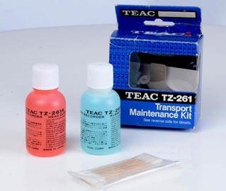
TZ-261 HEAD AND RUBBER CLEANER
Cleaning of the Pinch Roller

After prolonged use the pinch roller will accumulate a film of oxide. Use only Fluid "B" from the TEAC TZ-261 kit as it is especially formulated for cleaning rubber surfaces. Do not use chlorothane as it will cause deterioration of the rubber roller.
NOTE: The newer tape formulations leave a gray or white residue which is difficult to detect. Regular cleaning schedules should be established rather than relying on observation.
Cleaning of the Cabinet
Ordinary furniture cleaner and polish can be used to maintain the attractive finish.
Cleaning the Faceplate
A soft cloth and mild cleaning fluids (non-abrasive) can be used to restore the luster of the faceplate. An oildamped cloth will also give good results, but take care not to get oil on the tape path components such as the pinch roller, capstan, etc.

TZ-255 OIL KIT
Demagnetizing

During long periods of use, the heads will become slightly magne tized. As a result, the high frequency will decrease, noise will develop, or in extreme cases the high regions will drop out or introduce noise into your valued pre-recorded tapes. To keep your recorder operating at optimum efficiency the heads should be demagnetized at least once every 50 hours of use, with a TEAC Model E-1, Head Demagnetizer, using the procedures outlined below:
- Turn off power to the tape deck.
- Attach the plastic protectors to the pole tips of the Demagnetizer.
- Plug the Demagnetizer cord in to an AC outlet.
- Depress the Demagnetizer power button, bring the tip close to the head and slowly move it up and down 4 or 5 times.
- Slowly draw it away from the head.
- The same demagnetizing procedure is followed on each head, capstan shaft, and the guide posts.
- After finishing the above procedure on each head, turn off power to the Demagnetizer ONLY after it has been drawn at least 12 inches away from the head.
![]()

Lubrication Procedures
Lubricate points listed below at every 1,000 hours of operation or once a year if equipment is infrequently used. Use TEAC TZ-255 oil or equivalent.
CAPSTAN SHAFT: Remove the dust cover by turning it counterclockwise with fingers, apply approximately 2 drops of oil to oil-chamber felt.

PINCH ROLLER SHAFT: Unscrew the cap with fingers, apply one drop of oil to the shaft bearing.

MOTORS: Each motor (capstan motor, 2 reel motors) has two oil tubes attached. Apply approximately 1 cc of oil to each motor tube. If oil "backs up" into the oiling tubes, or is not accepted by the motor, do not force it into the motor.

Do not apply excessive quantities of oil. Over lubrication can be a source of difficulty. Do not apply oil to any rubber parts. Should oil be spilled onto rubber parts, remove immediately with TEAC rubber cleaning fluid.
Lubrication should be accomplished immediately after use while equipment is still warm. After applying lubricant, leave tape deck in horizontal position for 1-2 hours until oil oil is thoroughly absorbed.
Possible Troubles and How to Cure Them
| Tape Transport | ||
| Problem | Cause | Corrective Action |
| Completely inoperative, VU Meter lamps not illuminated |
|
|
|
| |
| Capstan does not rotate, (VU Meter lamps illuminated) | Auto-shutoff arm not upright. | Correct arm position. |
| Pinch roller will not engage | Dummy Plug not inserted in the remote control socket. | Insert Dummy Plug. |
| Index counter not operating | Counter reset not cleared. | Depress reset button several times. |
| Pinch roller dragging (cannot be spun freely by hand) | Needs lubrication. | Remove pinch roller cover, apply 1 or 2 drops of oil, check by hand again. |
| Tape squeal noise |
|
|
|
| |
| Playback Operation | ||
| No sound |
|
|
|
| |
|
| |
| Poor sound quality |
|
|
|
| |
| Unstable sound (wow, flutter, pitch changes) |
|
|
|
| |
|
| |
| Record Operation | ||
| Record Lights do not illuminate. |
|
|
|
| |
| Does not record. Cannot hear audio at SOURCE OUTPUT position. |
|
|
|
| |
| Does not record. Cannot hear audio at TAPE-OUTPUT position. |
|
|
|
| |
| Sound quality is low, dull, to much hiss, etc. |
|
|
|
| |
|
| |
|
| |
| Distorted or garbled sound |
|
|
|
| |
Specifications/Optional Accessories
Specifications
Heads Three, 4 track - 4 channel and 2 channel, stereo or mono (with SIMUL-SYNC switch), erase, record and playback
Reel Size 10-1/2" and 7"
Tape Speed 15 ips and 7-1/2 ips (0.5%)
Motors 1 dual speed hysteresis synchronous capstan motor
2 eddy current induction reel motors
Wow and Flutter 0.04% at 15 ips
0.06% at 7-l/2 ips
Frequency Response 25- 24,000 Hz (±3 d B, 30-22,000 Hz) at 15 ips
25-22,000 Hz (±3 dB, 30-20,000 Hz) at 7- l/ 2 ips
Signal to Noise Ratio 55 dB
Harmonic Distortion 1% at 1,000 Hz normal operating level
Stereo Channel Separation 55 dB at 1,000 Hz
Fast Winding Time 140 seconds for 1,800 feet
Inputs Line: 0.1 V, 50,000 ohms or more
Microphone: 0.25 mV/ -72 dB (600-10,000 ohms)
Outputs Line: 0.775V for load impedance of 10,000 ohms or more
Headphones: 8 - 400 ohms
Power Requirements 117 V AC, 60Hz 138 W
Dimensions 20-1/2"(H) X 17-3/ 8" (W) X 8-3/4" (D)
Weight 50 lbs. net
Standard Accessories Empty reel
Reel adaptor
Input-output connection cord
Oil
Fuse
Cleaning stick
Silicone cloth
Rubber feet
AC power cord
Reel height adjusting sheet
Splicing tape
Specifications were determined using low noise tape. Feature and specifications subject to change without notice.
Optional Accessories
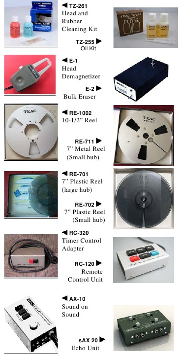
Documents / ResourcesDownload manual
Here you can download full pdf version of manual, it may contain additional safety instructions, warranty information, FCC rules, etc.
Advertisement


Need help?
Do you have a question about the 3340S and is the answer not in the manual?
Questions and answers