Advertisement
- 1 INTRODUCTION
- 2 GENERAL SAFETY RULES
-
3
1/2 In. CORDLESS BRUSHLESS IMPACT WRENCH
- 3.1 TOOL PARTS
- 3.2 Features
- 3.3 INTENDED USE
- 3.4 VIBRATION
- 3.5 NOISE
- 3.6 SAFETY WARNINGS
-
3.7
FUNCTIONAL DESCRIPTION
- 3.7.1 INSTALLING OR REMOVING BATTERY CARTRIDGE
- 3.7.2 Indicating the remaining battery capacity
- 3.7.3 Tool/battery protection system
- 3.7.4 SWITCH ACTION
- 3.7.5 Lighting up the front lamp
- 3.7.6 Reversing switch action
- 3.7.7 Speed change
- 3.7.8 Selecting the action mode
- 3.7.9 Adjusting the fastening torque
- 3.8 ASSEMBLY
- 3.9 OPERATION
- 3.10 MAINTENANCE
- 3.11 OPTIONAL ACCESSORIES
- 4 1/4 In. HEX HEAD CORDLESS BRUSHLESS IMPACT DRIVER
- 5 Documents / Resources
INTRODUCTION
This product has been carefully engineered and manufactured to give you dependable operation. Please read this manual thoroughly before operating your new product, as it contains the information you need to become familiar with its features and obtain the performance that will bring you continued enjoyment for many years. Please keep this manual on file for future reference.
GENERAL SAFETY RULES
FOR ALL BATTERY OPERATED TOOLS

READ AND UNDERSTAND ALL INSTRUCTIONS.
Failure to follow all instructions listed below, may result in electric shock, fire and /or serious personal injury.
Work area
- Keep work area clean and well lit. Cluttered and dark areas invite accidents.
- Do not operate power tools in explosive atmospheres, such as in the presence of flammable liquids, gases or dust. Power tools create sparks which may ignite the dust or fumes.
- Keep children and bystanders away while operating a power tool. Distractions can cause you to lose control
Electrical Safety
- Do not abuse the cord. Never use the cord to carry the tool. Keep cord away from heat, oil, sharp edges, or moving parts. Replace damaged cords immediately. Damaged cords may create a fire. (The following applies only to tools with a separate battery pack)
- A battery operated tool with integral batteries or a separate battery pack must be recharged only with the specified charger for the battery. A charger that may be suitable for one type of battery may create a risk of fire when used with another battery.
Personal Safety
- Stay alert, watch what you are doing and use common sense when operating a power tool. Do not use a power tool while you are tired or under the influence of drugs, alcohol or medication. A moment of inattention while operating power tools may result in serious personal injury.
- Dress properly. Do not wear loose clothing or jewelry. Contain long hair. Keep your hair, clothing, and gloves away from moving parts. Loose clothes, jewelry, or long hair can be caught in moving parts.
- Avoid accidental starting. Be sure switch is in the locked or off position before inserting batter pack. Carrying tools with your finger on the switch invites accidents.
- Do not overreach. Keep proper footing and balance at all times. Proper footing and balance enable better control of the tool in unexpected situations
- Use safety equipment. Always wear eye protection, Dust mask, non-skid safety shoes, hard hat, or hearing protection must be used for appropriate conditions.
Power tool use and care
- Use clamps or other practical ways to secure and support the work piece to a stable platform. Holding the work piece by hand or against your body is unstable and may lead to loss of control.
- Do not force tool. Use the correct tool for your application. The correct tool will do the job better and safer at the rate for which it is designed.
- Do not use tool if switch does not turn it on of off. A tool that cannot be controlled with the switch is dangerous and must be repaired.
- Store idle tools out of reach of children and other untrained persons. Tools are dangerous in the hands of untrained users
- Maintain tools with care. Keep cutting tools sharp and clean. Properly maintained tools with sharp cutting edge are less likely to bind and are easier to control.
- Check for misalignment or binding of moving parts, breakage of parts, and any other condition that may affect the tool's operation. If damaged, have the tool serviced before using. Many accidents are caused by poorly maintained tools.
- Use only accessories that are supplied with your model. Other accessories that may not be suitable for this tool and may create a risk of injury when used.
Specific safety rules
- Hold tool by insulated gripping surfaces when performing an operation where the cutting tool may contact hidden wiring. Contact with a "live" wire will also make exposed metal parts of the tool "live" and shock the operator.
- keep hands clear of moving parts.
- Do not touch moving parts, Allow the power tool accessories (bit and blades etc)to cool before touching them. They can become extremely hot during use and can burn your skin.
- Always wear protective safety glasses when operating power tools. Wear a face mask when environment is dusty.
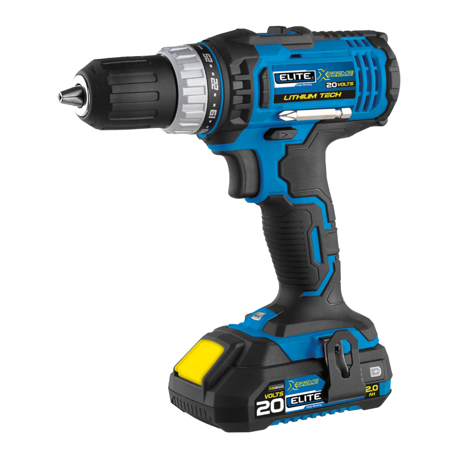
1/2 In. CORDLESS BRUSHLESS IMPACT WRENCH
TOOL PARTS

- Keyless Chuck
- Torque Adjusting Ring
- Action Mode Changing Ring
- Speed Change Lever
- Switch Trigger
- Reversing Switch Lever
- Soft Handle
- Work Lamp
- Button of Battery Cartridge
- Battery Cartridge
- Hook
Features
| Voltage | 20V (Li - ion) |
| Impact | 0 - 7.500/ 0 - 30.000BPM |
| Speed | 0 - 500 / 0 - 2.000RPM |
| Max torque | 55 N.m |
| Torque settings | 21 + 3 |
| Chuck | 2 - 13mm (1/2") |
Due to our continuing program of research and development, the specifications herein are subject to change without notice.
Specifications may differ from country to country.
The weight may differ depending on the attachment(s), including the battery cartridge.
Batteries for this model
XB0220 (2.0 Ah battery) - XB0420 (4.0 Ah battery) – XB0520 (5.0 Ah battery) XCB20 (2.4 Ah charger)
Some of the battery cartridges & Chargers listed above may not be available depending on your region of residence.
Only use the battery cartridges & chargers listed above. Use of any other battery cartridges & chargers may cause injury and/or fire.
INTENDED USE
The tool is intended for impact drilling in brick, brickwork and masonry. It is also suitable for screw driving and drilling without impact in wood, metal, ceramic and plastic.
VIBRATION
The vibration total value (tri-axial vector sum) determined according to EN62841-2-1:
Work mode: impact drilling into concrete
Vibration emission (a hID): 3,1 m/s2
Uncertainty (K): 1,5 m/s2
Work mode: drilling into metal
Vibration emission (a): 2,5 m/s2 o menos
Uncertainty (K): 1,5 m/s2
 NOTE: The declared vibration emission value has been measured in accordance with the standard test method and may be used for comparing one tool with another.
NOTE: The declared vibration emission value may also be used in a a preliminary assessment of exposure.
The vibration emission during actual use of the power tool can differ from the declared emission value depending on the ways in which the tool is used.
Be sure to identify safety measures to protect the operator that are based on an estimation of exposure in the actual conditions of use (taking account of all parts of the operating cycle such as the times when the tool is switched off and when it is running idle in addition to the trigger time).
NOISE
The typical A-weighted noise level determined according to EN62841-2-1:
Sound pressure level (LpA): 75,3 dB(A)
Uncertainty (K): 3 dB(A)
The noise level under working may exceed 80 dB (A).
Wear ear protection.
SAFETY WARNINGS
General power tool safety warnings
Read all safety warnings, instructions, illustrations and specifications provided with this power tool. Failure to follow all instructions listed below may resulting electric shock, fire and/or serious injury.
Save all warnings and instructions for the future reference.
The term "power tool" in the warnings refers to your mains-operated (corded) power tool or battery-operated (cordless) power tool.
WORK AREA SAFETY
- Keep work area clean and well lit. Cluttered or dark areas invite accidents.
- Do not operate power tools in explosive atmospheres, such as in the presence of flammable liquids, gases or dust. Power tools create sparks which may ignite the dust or fumes.
- Keep children and bystanders away while operating a power tool. Distractions can cause you to lose control.
ELECTRICAL SAFETY
- Power tool plugs must match the outlet. Never modify the plug in any way. Do not use any adapter plugs with earthed (grounded) power tools. Unmodified plugs and matching outlets will reduce risk of electric shock.
- Avoid body contact with earthed or grounded surfaces, such as pipes, radiators, ranges and refrigerators. There is an increased risk of electric shock if your body is earthed or grounded.
- Do not expose power tools to rain or wet conditions. Water entering a power tool will increase the risk of electric shock.
- Do not abuse the cord. Never use the cord for carrying, pulling or unplugging the power tool. Keep cord away from heat, oil, sharp edges or moving parts. Damaged or entangled cords increase the risk of electric shock.
- When operating a power tool outdoors, use an extension cord suitable for outdoor use. use of a cord suitable for outdoor use reduces the risk of electric shock.
- If operating a power tool in a damp location is unavoidable, use a residual current device (RCD) protected supply. Use of an RCD reduces the risk of electric shock.
- Power tools can produce electromagnetic fields (EMF) that are not harmful to the user. However, users of pacemakers and other similar medical devices should contact the maker of their device and/ or doctor for advice before operating this power tool.
PERSONAL SAFETY
- Stay alert, watch what you are doing and use common sense when operating a power tool. Do not use a power tool while you are tired or under the influence of drugs, alcohol or medication. A moment of inattention while operating power tools may result in serious personal injury.
- Use personal protective equipment. Always wear eye protection. Protective equipment such as a dust mask, non-skid safety shoes, hard hat or hearing protection used for appropriate conditions will reduce personal injuries.
- Prevent unintentional starting. Ensure the switch is in the off-position before connecting to power source and/or battery pack, picking up or carrying the tool. Carrying power tools with your finger on the switch or energising power tools that have the switch on invites accidents.
- Remove any adjusting key or wrench before turning the power tool on. A wrench or a key left attached to a rotating part of the power tool may result in personal injury.
- Do not overreach. Keep proper footing and balance at all times. This enables better control of the power tool in unexpected situations.
- Dress properly. Do not wear loose clothing or jewellery. Keep your hair and clothing away from moving parts. Loose clothes, jewellery or long hair can be caught in moving parts.
- If devices are provided for the connection of dust extraction and collection facilities, ensure these are connected and properly used. Use of dust collection can reduce dust-related hazards.
- Do not let familiarity gained from frequent use of tools allow you to become complacent and ignore tool safety principles. A careless action can cause severe injury within a fraction of a second.
- Always wear protective goggles to protect your eyes from injury when using power tools. The goggles must comply with ANSI Z87.1 in the USA, EN 166 in Europe, or AS/NZS1336in Australia/New Zealand. In Australia/NewZealand, it is legally required to wear a face shield to protect your face, too.
It is an employer's responsibility to enforce the use of appropriate safety protective equipments by the tool operators and by other persons in
the immediate working area.

Power tool use and care
- Do not force the power tool. Use the correct power tool for your application. The correct power tool will do the job better and safer at the rate for which it was designed.
- Do not use the power tool if the switch does not turn it on and off. Any power tool that cannot be controlled with the switch is dangerous and must be repaired.
- Disconnect the plug from the power source and/or remove the battery pack, if detachable, from the power tool before making any adjustments, changing accessories, or storing power tools. Such preventive safety measures reduce the risk of starting the power tool accidentally.
- Store idle power tools out of the reach of children and do not allow persons unfamiliar with the power tool or these instructions to operate the power tool. Power tools are dangerous in the hands of untrained users.
- Mount a in power tools and accessories. Check for misalignment or binding of moving parts, breakage of parts and any other condition that may affect the power tool's operation. If damaged, have the power tool repaired before use. Many accidents are caused by poorly maintained power tools.
- Keep cutting tools sharp and clean. Properly maintained cutting tools with sharp cutting edges are less likely to bind and are easier to control.
- Use the power tool, accessories and tool bits etc. in accordance with these instructions, taking into account the working conditions and the work to be performed. Use of the power tool for operations different from those intended could result in a hazardous situation.
- Keep handles and grasping surfaces dry, clean and free from oil and grease. Slippery handles and grasping surfaces do not allow for safe handling and control of the tool in unexpected situations.
- When using the tool, do not wear cloth work gloves which may be entangled. The entanglement of cloth work gloves in the moving parts may result in personal injury.
Battery tool use and care
- Recharge only with the charger specified by the manufacturer. A charger that is suitable for one type of battery pack may create a risk of fire when used with another battery pack.
- Use power tools only with specifically designated battery packs. Use of any other battery packs may create a risk of injury and fire.
- When battery pack is not in use, keep it away from other metal objects, like paper clips, coins, keys, nails, screws or other small metal objects, that can make a connection from one terminal to another. Shorting the battery terminals together may cause burns or afire.
- Under abusive conditions, liquid may bee ejected from the battery; avoid contact. If contact accidentally occurs, flush with water. If liquid contacts eyes, additionally seek medical help. Liquid ejected from the battery may cause irritation or burns.
- Do not use a battery pack or tool that is damaged or modified. Damaged or modified batteries may exhibit unpredictable behaviour resulting in fire, explosion or risk of injury.
- Do not expose a battery pack or tool to fire or excessive temperature. Exposure to fire or temperature above 130°C may cause explosion.
- Follow all charging instructions and do not charge the battery pack or tool outside the temperature range specified in the instructions. Charging improperly or at temperatures outside the specified range may damage the battery and increase the risk of fire.
Servicet
- Have your power tool serviced by a qualified repair person using only identical replacement parts. This will ensure that the safety of the power tool is maintained.
- Never service damaged battery packs. Service of battery packs should only be performed by the manufacturer or authorized service providers.
- Follow instruction for lubricating and changing accessories.
CORDLESS HAMMER DRIVER DRILL SAFETY WARNINGS
- Wear ear protectors when impact drilling. Exposure to noise can cause hearing loss.
- Use auxiliary handle(s), if supplied with the tool. Loss of control can cause personal injury.
- Hold power tool by insulated gripping surfaces, when performing an operation where the cutting accessory may contact hidden wiring. Cutting accessory contacting a "live" wire may make exposed metal parts of the power tool "live" and could give the operator an electric shock.
- Hold power tool by insulated gripping surfaces, when performing an operation where the fastener may contact hidden wiring. Fasteners contacting a "live" wire may make exposed metal parts of the power tool "live" and could give the operator an electric shock.
- Always be sure you have a firm footing. Be sure no one is below when using the tool in high locations.
- Hold the tool firmly.
- Keep hands away from rotating parts.
- Do not leave the tool running. Operate the tool only when hand-held.
- Do not touch the drill bit or the work piece immediately after operation; they may be extremely hot and could burn your skin.
- Some material contains chemicals which may be toxic. Take caution to prevent dust inhalation and skin contact. Follow material supplier safety data.
- If the drill bit cannot be loosened even you open the jaws, use pliers to pull it out. In such a case, pulling out the drill bit by hand may result in injury by its sharp edge.
SAVE THESE INSTRUCTIONS
DO NOT let comfort or familiarity with product (gained from repeated use) replace strict adherence to safety rules for the subject product. MISUSE or failure to follow the safety rules stated in this instruction manual may cause serious personal injury.
IMPORTANT SAFETY INSTRUCTIONS FOR BATTERY CARTRIDGE
- Before using battery cartridge, read all instructions and cautionary markings on
- battery charger,
- battery, and
- product using battery.
- Do not disassemble battery cartridge.
- If operating time has become excessively shorter, stop operating immediately. It may result in a risk of overheating, possible burns and even an explosion.
- If electrolyte gets into your eyes, rinse them out with clear water and seek medical attention right away. It may result in loss of your eye sight.
- Do not short the battery cartridge:
- Do not touch the terminals with any conductive material.
- Avoid storing battery cartridge in a container with other metal objects such as nails, coins, etc.
- Do not expose battery cartridge to water or rain. A battery short can cause a large current flow, overheating, possible burns and even a breakdown.
- Do not store the tool and battery cartridge in locations where the temperature may reach or exceed 50°C.
- Do not incinerate the battery cartridge even if it is severely damaged or is completely worn out. The battery cartridge can explode in afire.
- Be careful not to drop or strike battery.
- Do not use a damaged battery.
- The contained lithium-ion batteries are subject to the Dangerous Goods Legislation requirements. For commercial transports e.g. by third parties, forwarding agents, special requirement on packaging and labeling must be observed. For preparation of the item being shipped, consulting an expert for hazardous material is required. Please also observe possibly more detailed national regulations. Tape or mask off open contacts and pack up the battery in such a manner that it cannot move around in the packaging.
- Follow your local regulations relating to disposal of battery.
- Use the batteries only with the products specified by Elite. Installing the batteries to non-compliant products may result in a fire, excessive heat, explosion, or leak of electrolyte.
SAVE THESE INSTRUCTIONS

Only use genuine Elite batteries. Use of non-genuine Elite batteries, or batteries that have been altered, may result in the battery bursting causing fires, personal injury and damage. It will also void the Elite warranty for the Elite tool and charger.
 Tips for maintaining maximum battery life
- Charge the battery cartridge before completely discharged. Always stop tool operation and charge the battery cartridge when you notice less tool power.
- Never recharge a fully charged battery cartridge. Overcharging shortens the battery service life.
- Charge the battery cartridge with room temperature at 5°C - 45°C. Let a hot battery cartridge cool down before charging it.
- Charge the battery cartridge if you do not use it for a long period (more than six months).
FUNCTIONAL DESCRIPTION
Always be sure that the tool is switched off and the battery cartridge is removed before adjusting or checking function on the tool.
INSTALLING OR REMOVING BATTERY CARTRIDGE
Always switch off the tool before installing or removing of the battery cartridge.
Hold the tool and the battery cartridge firmly when installing or removing battery cartridge. Failure to hold the tool and the battery cartridge firmly may cause them to slip off your hands and result in damage to the tool and battery cartridge and a personal injury.

- Button
- Battery cartridge
Always install the battery cartridge fully until the red indicator cannot be seen. If not, it may accidentally fall out of the tool, causing injury to you or someone around you.
Do not install the battery cartridge forcibly. If the cartridge does not slide in easily, it is not being inserted correctly.
To remove the battery cartridge, slide it from the tool while sliding the button on the front of the cartridge. To install the battery cartridge, align the tongue on the battery cartridge with the groove in the housing and slip it into place. Insert it all the way until it locks in place with a little click.
Indicating the remaining battery capacity

- Indicator lamps
- Check button
Press the check button on the battery cartridge to indicate the remaining battery capacity

NOTE: Depending on the conditions of use and the ambient temperature, the indication may differ slightly from the actual capacity
Tool/battery protection system
The tool is equipped with a tool/battery protection system. This system automatically cuts off power to the motor to extend tool and battery life. The tool will automatically stop during operation if the tool or battery is placed under one of the following conditions:
Overload protection
When the tool/battery is operated in a manner that causes it to draw an abnormally high current, the tool stops automatically. In this situation, turn the tool off and stop the application that caused the tool to become overloaded. Then turn the tool on to restart.
Overheat protection
When the tool/battery is overheated, the tool stops automatically. In this situation, let the tool/battery cool before turning the tool on again.
Overdischarge protection
When the battery capacity is not enough, the tool stops automatically. In this case, remove the battery from the tool and charge the battery.
SWITCH ACTION

- Switch trigger
Before installing the battery cartridge into the tool, always check to see that the switch trigger actuates properly and returns to the "OFF" position when released.
To start the tool, simply pull the switch trigger. Tool speed is increased by increasing pressure on the switch trigger. Release the switch trigger to stop.
Lighting up the front lamp

- Lamp
Do not look in the light or see the source of light directly.
Pull the switch trigger to light up the lamp. The lamp keeps on lighting while the switch trigger is being pulled. The lamp goes out approximately 10 seconds after releasing the switch trigger.
NOTE: When the tool is overheated, the tool stops automatically and the lamp starts flashing. In this case, release the switch trigger. The lamp turns off in 10 seconds.
NOTE: Use a dry cloth to wipe the dirt off the lens of the lamp. Be careful not to scratch the lens of lamp, or it may lower the illumination.
Reversing switch action
Always check the direction of rotation before operation.

Use the reversing switch only after the tool comes to a complete stop. Changing the direction of rotation before the tool stops may damage the tool.
When not operating the tool, always set the reversing switch lever to the neutral position.
This tool has a reversing switch to change the direction of rotation. Depress the reversing switch lever from the A side for clockwise rotation or from the B side for counterclockwise rotation.
When the reversing switch lever is in the neutral position, the switch trigger cannot be pulled.
Speed change

- Speed change lever
Always set the speed change lever fully to the correct position. If you operate the tool with the speed change lever positioned halfway between the "1" side and "2" side, the tool may be damaged.
Do not use the speed change lever while the tool is running. The tool may be damaged.
| Displayed Number | Speed | Torque | Applicable operation |
| 1 | Low | High | Heavy loading operation |
| 2 | High | Low | Light loading operation |
To change the speed, switch off the tool first. Push the speed change lever to display "2" for high speed or "1" for low speed but high torque. Be sure that the speed change lever is set to the correct position before operation.
If the tool speed is coming down extremely during the operation with display "2", push the lever to display "1" and restart the operation.
Selecting the action mode
Always set the ring correctly to your desired mode mark. If you operate the tool with the ring positioned halfway between the mode marks, the tool may be damaged.
When you change the position from "  " to other modes, it may be a little difficulty to slide the action mode changing ring. In this case, switch on and run the tool for a second at the " " position, then stop the tool and slide the ring to your desired position.

- Action mode changing ring
- Mark
- Arrow
 Drilling mode (rotation only)
 Hammer drilling mode (rotation with hammering)
 Screwdriving mode (rotation with clutch)
Select one mode suitable for your work. Turn the action mode changing ring and align the mark that you selected with the arrow on the tool body.
Adjusting the fastening torque

- Action mode changing ring
- Adjusting ring
- Graduation
- Arrow
The fastening torque can be adjusted in 21 levels by turning the adjusting ring. Align the graduations with the arrow on the tool body. You can get the minimum fastening torque at 1 and maximum torque at 21.
Before actual operation, drive a trial screw into your material or a piece of duplicate material to determine which torque level is required for a particular application. The following shows the rough guide of the relationship between the screw size and graduation.

ASSEMBLY
Always be sure that the tool is switched off and the battery cartridge is removed before carrying out any work on the tool.
Installing or removing driver bit/drill bit

- Sleeve
- Close
- Open
- Drill Bit
Turn the sleeve clockwise to open the chuck jaws. Place the driver bit/drill bit in the chuck as far as it will go. Turn the sleeve counterclockwise to tighten the chuck. To remove the driver bit/drill bit, turn the sleeve clockwise.
Installing hook
When installing the hook, always secure it with the screw firmly. If not, the hook may come off from the tool and result in the personal injury.

- Groove
- Hook
- Screw
The hook is convenient for temporarily hanging the tool. This can be installed on left side of the tool. To install the hook, insert it into a groove in the tool housing on either side and then secure it with a screw. To remove, loosen the screw and then take it out
OPERATION
Always insert the battery cartridge all the way until it locks in place. If not, it may accidentally fall out of the tool, causing injury to you or someone around you.
When the speed comes down extremely, reduce the load or stop the tool to avoid the tool damage.
Hold the tool firmly with one hand on the grip and the other hand on the bottom of the battery cartridge to control the twisting action.
NOTICE: Do not cover vents, or it may cause overheating and damage to the tool.

- Vent
Screw driving operation
Adjust the adjusting ring to the proper torque level for your work.
Make sure that the driver bit is inserted straight in the screw head, or the screw and/or driver bit may be damaged.
Place the point of the driver bit in the screw head and apply pressure to the tool. Start the tool slowly and then increase the speed gradually. Release the switch trigger as soon as the clutch cuts in.
NOTE: When driving wood screw, pre-drill a pilot hole 2/3 the diameter of the screw. It makes driving easier and prevents splitting of the workpiece.
Hammer drilling operation
There is a tremendous and sudden twisting force exerted on the tool/drill bit at the time of hole breakthrough, when the hole becomes clogged with chips and particles, or when striking reinforcing rods embedded in the concrete
First, turn the action mode changing ring so that the arrow on the tool body points to the marking. The adjusting ring can be aligned in any torque levels for this operation. Be sure to use a tungsten-carbide tipped drill bit. Position the drill bit at the desired location for the hole, then pull the switch trigger. Do not force the tool.
Light pressure gives best results. Keep the tool in position and prevent it from slipping away from the hole. Do not apply more pressure when the hole becomes clogged with chips or particles. Instead, run the tool at an idle, then remove the drill bit partially from the hole. By repeating this several times, the hole will be cleaned out and normal drilling may be resumed.
Drilling operation
First, turn the adjusting ring so that the arrow points to the ![]() marking. Then proceed as follows.
marking. Then proceed as follows.
Drilling in wood
When drilling in wood, the best results are obtained with wood drills equipped with a guide screw. The guide screw makes drilling easier by pulling the drill bit into the workpiece.
Drilling in metal
To prevent the drill bit from slipping when starting a hole, make an indentation with a center-punch and hammer at the point to be drilled. Place the point of the drill bit in the indentation and start drilling. Use a cutting lubricant when drilling metals. The exceptions are iron and brass which should be drilled dry.
Pressing excessively on the tool will not speed up the drilling. In fact, this excessive pressure will only serve to damage the tip of your drill bit, decrease the tool performance and shorten the service life of the tool.
Hold the tool firmly and exert care when the drill bit begins to break through the workpiece. There is a tremendous force exerted on the tool/drill bit at the time of hole break through.
A stuck drill bit can be removed simply by setting the reversing switch to reverse rotation in order to back out. However, the tool may back out abruptly if you do not hold it firmly.
Always secure workpieces in a vise or similar hold-down device.
If the tool is operated continuously until the battery cartridge has discharged, allow the tool to rest for 15 minutes before proceeding with a fresh battery.
MAINTENANCE
Always be sure that the tool is switched off and the battery cartridge is removed before attempting to perform inspection or maintenance.
NOTICE: Never use gasoline, benzine, thinner, alcohol or the like. Discoloration, deformation or cracks may result.
To maintain product SAFETY and RELIABILITY, repairs, any other maintenance or adjustment should be performed by Elite Authorized or Factory Service Centers, always using Elite replacement parts.
OPTIONAL ACCESSORIES
These accessories or attachments are recommended for use with your Elite tool specified in this manual. The use of any other accessories or attachments might present a risk of injury to persons. Only use accessory or attachment for its stated purpose.
If you need any assistance for more details regarding these accessories, ask your local Elite Service Center.
Drill bits
Driver bits
Hook
Elite genuine battery and charger
NOTE: Some items in the list may be included in the tool package as standard accessories. They may differ from country to country.
1/4 In. HEX HEAD CORDLESS BRUSHLESS IMPACT DRIVER
LIST OF COMPONENTS

- Head
- Head Cover
- Aluminum Cover
- Drive Switch
- Reverse Switch Lever
- Soft Grip
- Speed Adjustment Knob
- Work Light
- Battery Cartridge Button
- Battery Cartridge
- Speed Adjustment Indicator Lamp
- Hook
TECHNICAL DATA
Specs
| Voltage | 20V (Li - ion) |
| Head | 1/4" Hex head |
| Impact | 0 - 2.520/0 - 2.940/0 - 3.780BPM |
| Torque | 80 Nm. / 120 Nm. / 200 Nm. |
| Speed | 0 - 1.800/0 - 2.100/0 - 2.700RPM |
SWITCH ACTION

- Switch trigger
Before installing the battery cartridge into the tool, always check to see that the switch trigger actuates properly and returns to the "OFF" position when released.
To start the tool, simply pull the switch trigger. Tool speed is increased by increasing pressure on the switch trigger. Release the switch trigger to stop
Lighting up the front lamp

- Work Lamp
Do not look in the light or see the source of light directly.
Pull the switch trigger to light up the lamp. The lamp keeps on lighting while the switch trigger is being pulled. The lamp goes out approximately 10 seconds after releasing the switch trigger.
NOTE: Use a dry cloth to wipe the dirt off the lens of the lamp. Be careful not to scratch the lens of lamp, or it may lower the illumination.
Reversing switch action

- Reversing switch lever
Always check the direction of rotation before operation.
Use the reversing switch only after the tool comes to a complete stop. Changing the direction of rotation before the tool stops may damage the tool.
When not operating the tool, always set the reversing switch lever to the neutral position.
This tool has a reversing switch to change the direction of rotation. Depress the reversing switch lever from the A side for clockwise rotation or from the B side for counterclockwise rotation. When the reversing switch lever is in the neutral position, the switch trigger cannot be pulled.
Speed (Impact force) change
 change")
- Speed adjust indicator lamp
- Speed adjust button
- Three impact force adjust mode (hard, medium, and soft mode) are provided by this tool only when the tool rotating in clockwise direction through change the tool speed. This allows a tightening suitable to the work.
The impact force can not be adjusted when the tool is running. - To change the speed, depress the speed adjusting button each time to select the speed that you desired.
- Every time the speed adjust button is pressed, the indicator lamp will light on and changes in steps to indicate when the tool rotating in clockwise direction.
- Two loosen mode (fast loosen and slow loosen mode) are provided by this tool only when the tool rotating in anticlockwise direction.
- The tool rotating in fast loosen mode only with max impact force while the indicator lamp is light off and rotating in slow loosen mode with max impact force for only 2 second and then with minimum impact force while the indicator lamp is light on.
- Use the fast loosen mode to quickly loosen and take down the bolt or nut, or depress the speed adjusting button to change to the slow loosen mode to loosen the bolt or nut only.
- Below table for detail information of purpose use.
| Impact grade force | Speed | Purpose | Example of application |
| Hard | 0 - 1.800 | when force and Tightening speed are desired | Tightening underwork materials, tightening long screws, tightening bolts |
| Medium | 0 - 2.100 | when a good Tightening finishing is needed | Tightening finishing boards plaster boards. |
| Soft | 0 - 2.700 | whit less force Tightening to avoid screw thread breakage | Tightening sash screws, tightening small screws such as M6 |
NOTE: The indicator lamp go out approximately 10 seconds after releasing the switch trigger to save the battery power.
NOTE: While pulling the switch trigger, the impact force grade cannot be changed.
ASSEMBLY
Always be sure that the tool is switched off and the battery cartridge is removed before carrying out any work on the tool.
Installing or removing driver bit/ socket bit

Use only driver bit/socket bit that has inserting portion shown in the figure. Do not use any other driver bit/ socket bit.
For tool with shallow driver bit hole
| A = 12mm B = 9mm | Use only these of driver bit. Follow the procedure 1. |
Procedure 1
For tool without one-touch type sleeve

To remove the driver bit, pull the sleeve in the direction of the arrow and pull the driver bit out.
NOTE: If the driver bit is not inserted deep enough into the sleeve, the sleeve will not return to its original position and the driver bit will not be secured. In this case, try re-inserting the bit according to the instructions above.
NOTE: When it is difficult to insert the driver bit, pull the sleeve and insert it into the sleeve as far as it will go.
NOTE: After inserting the driver bit, make sure that it is firmly secured. If it comes out, do not use it.
Installing hook
When installing the hook, always secure it with the screw firmly. If not, the hook may come off from the tool and result in the personal injury.

- Groove
- Hook
- Screw
The hook is convenient for temporarily hanging the tool. This can be installed on left side of the tool. To install the hook, insert it into a groove in the tool housing on left side and then secure it with a screw. To remove, loosen the screw and then take it out.
OPERATION
Always insert the battery cartridge all the way until it locks in place. If not, it may accidentally fall out of the tool, causing injury to you or someone around you.
Screw driving operation

For screw driving, hold the tool firmly and place the point of the driver bit in the screw head. Apply forward pressure to the tool to the extent that the bit will not slip off the screw and turn the tool on to start operation.
Fastening operation
For bolts fastening, hold the tool firmly and place the socket bolt over the bolt or nut. Turn the tool on and fasten for the proper fastening time.
The proper fastening torque may differ depending upon the kind or size of the screw/bolt, the material of the workpiece to be fastened, etc. The relation between fastening torque and fastening time is shown in the figures.
Proper fastening torque for standard bolt

- Fastening time (second)
- Fastening torque
Proper fastening torque for high tensile bolt
- Fastening time (second)
- Fastening torque
NOTICE: If you use a spare battery to continue the operation, rest the tool at least 15 min.
NOTE: Use the proper bit for the head of the screw/ bolt that you wish to use.
NOTE: When fastening M8 or smaller screw, carefully adjust pressure on the switch trigger so that the screw is not damaged.
NOTE: Hold the tool pointed straight at the screw.
NOTE: If the impact force is too strong or you tighten the screw for a time longer than shown in the figures, the screw or the point of the driver bit may be over-stressed, stripped, damaged, etc. Before starting your job, always perform a test operation to determine the proper fastening time for your screw.
The fastening torque is affected by a wide variety of factors including the following. After fastening, always check the torque with a torque wrench.
- When the battery cartridge is discharged almost completely, voltage will drop and the fastening torque will be reduced.
- Driver bit or socket bit
Failure to use the correct size driver bit or socket bit will cause a reduction in the fastening torque. - Bolt
Even though the torque coefficient and the class of bolt are the same, the proper fastening torque will differ according to the diameter of bolt.
Even though the diameters of bolts are the same, the proper fastening torque will differ according to the torque coefficient, the class of bolt and the bolt length. - The manner of holding the tool or the material of driving position to be fastened will affect the torque.
- Operating the tool at low speed will cause a reduction in the fastening torque.
NOTICE: Do not cover vents when operation, or it may cause over-heating and damage to the tool.

- Vent
MAINTENANCE
Always be sure that the tool is switched off and the battery cartridge is removed before attempting to perform inspection or maintenance.
NOTICE: Never use gasoline, benzine, thinner, alcohol or the like. Discoloration, deformation or cracks may result.
To maintain product SAFETY and RELIABILITY, repairs, any other maintenance or adjustment should be performed by Elite Authorized or Factory Service Centers, always using Elite replacement parts.
OPTIONAL ACCESSORIES
These accessories or attachments are recommended for use with your Elite tool specified in this manual. The use of any other accessories or attachments might present a risk of injury to persons. Only use accessory or attachment for its stated purpose.
If you need any assistance for more details regarding these accessories, ask your local Elite Service Center.
Documents / ResourcesDownload manual
Here you can download full pdf version of manual, it may contain additional safety instructions, warranty information, FCC rules, etc.
Advertisement


Need help?
Do you have a question about the ADVANCE Series and is the answer not in the manual?
Questions and answers