Advertisement

TO THE READER
This Workshop Manual provides service personnel with information about the mechanisms, service and maintenance of the construction machine. The Manual is divided into three sections, General, Mechanisms and Service.
- General
This section contains information such as engine and equipment ID numbers, general precautions, maintenance schedules, inspections and maintenance items. - Mechanisms
This section describes the structure of mechanisms and explains their functions. Be sure that you fully understand this Mechanisms section prior to performing any service work, such as troubleshooting or when performing any disassembly or assembly work. - Service
This section contains information and procedures for performing maintenance on the machine, such as troubleshooting, service specification tables, torque specifications, items to be inspected and adjusted, disassembly and assembly procedures, as well as precautions, maintenance standard values and usage limits.
All of the illustrations, specifications and other information in this manual were created based on the latest model at the time of publication.
Please be aware that changes to the content may be made without prior notice.
 NOTE
NOTE
- Applicable Models
| Model | Engine |
| SSV65 | V2607-CR-TE4-SL1 V2607-CR-TE4-SL1-Q |

- Please refer to the "Workshop Manual" below for information about the engine.
Workshop manual title:
Diesel engine V2607-CR-E4B, V2607-CR-TE4B, V3307-CR-TE4B
WEB PDF code: 9Y111-11043
Booklet print code: 9Y121-11043
CD-ROM code: 9Y131-11043
INFORMATION
SAFETY FIRST
 SAFETY FIRST SAFETY FIRST |
| This symbol, the industry's "Safety Alert Symbol", is used throughout this manual and on labels on the machine itself to warn of the possibility of personal injury. Read these instructions carefully. |
| It is essential that you read the instructions and safety regulations before you attempt to repair or use this unit. |

|

|

|
| |
|
| NOTE |
|
SAFETY PRECAUTIONS FOR WORK
PRECAUTIONS BEFORE WORKING
Before servicing and repairing
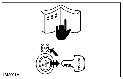
- Be sure to read all of the instructions and safety precautions in this manual and the operator's manual, as well the various labels affixed to the machine.
- Be sure to stop the engine when you are out of the driver's seat to clean and inspect the machine body and machine itself, or to check and adjust various parts.
- Choose non-hazardous flat, firm ground for inspection.
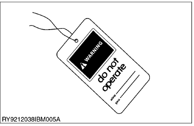
- When performing maintenance on the equipment, hang the DO NOT OPERATE sign where it will be obvious from and around the driver's seat.
- When performing maintenance or repairs, always lower attachments to the ground, stop the engine and secure the tracks with blocks.
- When performing maintenance on the equipment, always disconnect the negative battery cable.
- Before using tools, make sure you understand how to use them correctly and use tools in good condition and of the right size for the job.
Be Ready for an Emergency
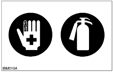
- Keep a first-aid kit and fire extinguisher close at hand so you can use it when needed.
- Keep emergency contact information for doctors, hospitals and ERs handy.
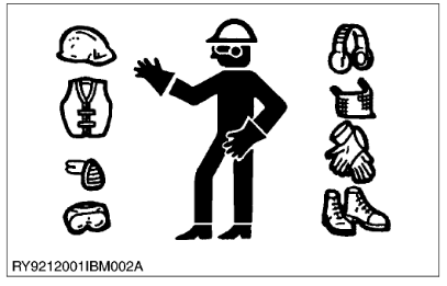
- Wear clothes appropriate for working on equipment. Do not wear loose-fitting clothes as they may catch on the machine controls.
- When working on the equipment, use all safety gear, such as a helmet, safety glasses and shoes, that are required by law or regulation.
- Never perform maintenance while drowsy or under the influence of alcohol or drugs.
PRECAUTIONS WHEN WORKING
- Stop the machine on a hard and level location and make sure the area around the machine is free of obstacles and hazardous materials. When parking the machine indoors, select a spot that can be properly ventilated.
- When performing work such as with a hammer, fragments may go flying, so make sure only authorized persons are around the machine. Before servicing the machine, clean it off so there is no mud, debris, oil or the like sticking to it.
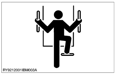
- Before getting on/off of the machine, clean off around the steps so there is no mud on them. Always give yourself 3-point support when getting on/off the machine.
- 3-point support means using both legs and one hand or both hands and one leg as you climb up/down.
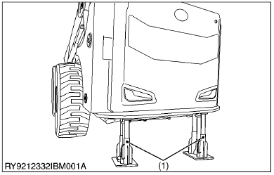
(1)Safety Stand
- When you need to access the underside of the machine for maintenance purposes, but sure to support the machine with a safety stand. Getting under the machine while supporting the machine by machine's own hydraulic cylinder or using a hydraulic jack can be extremely dangerous in the event of a hydraulic fluid leakage or similar mishap.
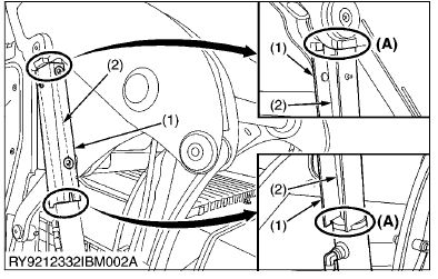
(1) Lift Arm Stopper
(2) Arm Cylinder Rod
(A) FIT
- Make sure the lift arm stopper is properly engaged before performing any work beneath raised lift arms. Never attempt to do any work or move under the lift arms when they are not properly supported.
- Keep in mind that the lift arms may fall whenever hydraulic lines are disconnected, loosened, or removed. Any malfunction or failure in the hydraulics can also cause lift arms to drop.
- Always perform the necessary repairs or service whenever the lift arm stopper becomes damaged or malfunctioned, or part are missing. Damaged or malfunction the lift arm stopper may cause the lift arms to fall causing serious injury or death.
- Do not raise or lower the cabin while the engine is running as it may move, cause the machine to become unstable, resulting in serious injury or death. Always lower the working parts of the machine to the ground and stop the engine before attempting to raise or lower the cabin.
- Make sure the cabin is properly and securely supported with a stopper when tilted to prevent if from falling and causing serious injury. (See, "CAB TILT" page)
![]()
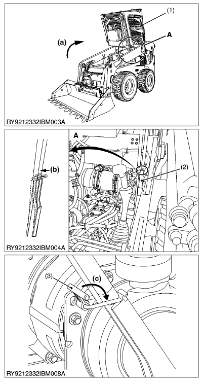
(1) Cabin
(2) Stopper
(3) Stopper Lock
(a) RAISE
(b) ENGAGE
(c) LOCK
- When opening the rear door to perform maintenance, be sure to insert the pin into the "LOCKED" position to hold the door in place.
![]()
(3) Rear Door
(4) Pin
Starting the Machine Safely
- Before starting the engine, always sit in the driver's seat and make sure the area is safe and clear.
- As it is dangerous, never start the engine from anywhere but the driver's seat.
- Always check and make sure control lever(s) are not engaged before starting the engine.
- Never start the engine by hot-wiring the starter circuit. This is not only dangerous, but may damage the machine.
- Whenever it is necessary to open the engine covers or hood in order to service the machine, always prop them open.
- If it is absolutely necessary to run the engine while working on the machine, make sure you are clear of all rotating or moving parts. Also take care not to leave anything, such as tools or rags, near any moving parts.
- The engine, muffler, radiator, hydraulic line, etc., have parts that remain very hot even after the engine has been stopped. Be sure to avoid these parts, as touching them can result in burns. Radiator coolant, hydraulic fluid and oil also remain hot. Therefore, do not attempt to remove caps and plugs, etc., before these fluids have sufficiently cooled.
- Make sure the coolant temperature has dropped sufficiently before opening the radiator cap. Also, since the inside of the radiator is pressurized, when removing the cap, first loosen it to release the pressure before removing the cap completely.
- The pressure in the hydraulic circuit stays at pressure even after the engine stops. Before removing parts, such as hydraulic devices from the machine, first release the pressure. Please note that when releasing residual pressure, the machine itself and/or implements may move without warning, so be very careful when releasing the pressure.
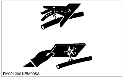
- Oil gushing out under pressure is extremely dangerous as it may pierce your skin or your eyes. Similarly, oil leaking out of pinholes is not visible. So when checking for oil leaks, always wear safety glasses and gloves and use a piece of cardboard or a wood block to shield yourself from oil.
No Smoking or Open Flames while Fueling
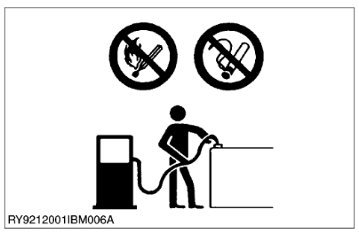
- Fuel is extremely flammable and dangerous. Never smoke near fuel. If fuel is spilled on the machine, its engine, or electrical parts, it may cause a fire. If fuel is spilled, wipe it all up immediately.
- Never smoke while filling the machine with fuel. And always tighten the fuel cap securely and wipe up any spilled fuel.
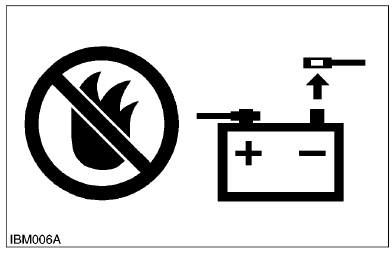
- Always wear safety glasses and gloves when handling the battery.
- The gas generated by the battery is flammable. Never weld or use tools like a grinder near the battery. And never smoke near it.
- When disconnecting the battery, always disconnect the negative cable first. When connecting the battery, always connect the positive cable first.
Dispose of Waste Fluids Properly

- Never dispose of waste fluids on the ground, in the gutter, a river, pond or lake. Always dispose of hazardous substances like waste oil, coolant and electrolytic fluid in accordance with the relevant environmental protection regulations.
- Keep the safety plates clean so they can be read. If a safety plate is damaged and comes off or becomes illegible, put a plate with the same warnings back in its place.
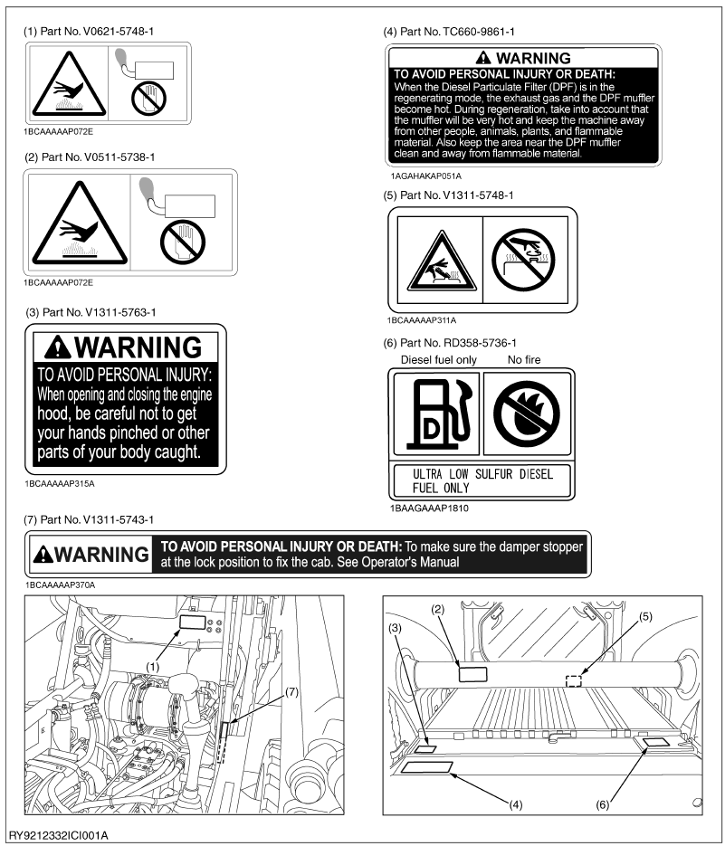
SAFETY DECALS
LOCATIONS


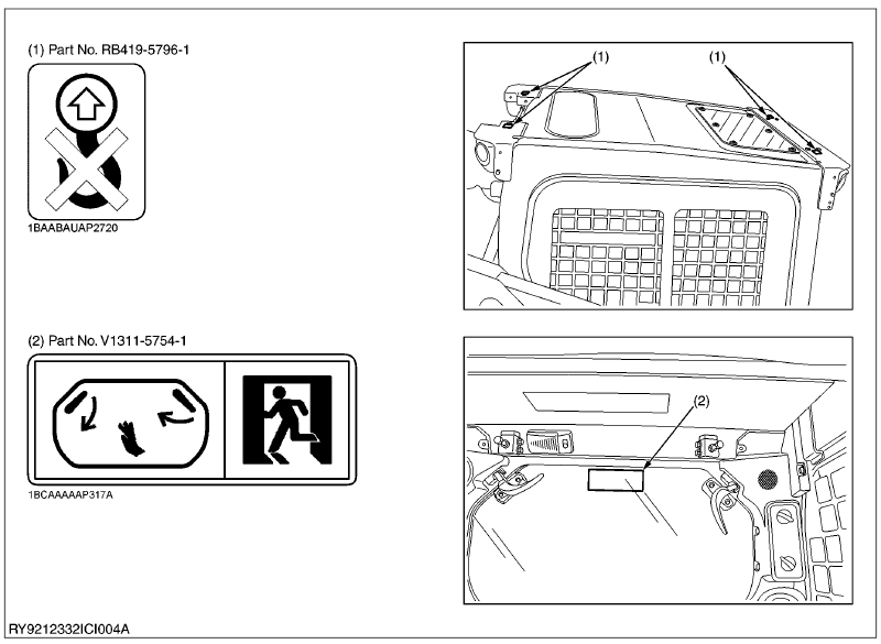
CARE OF LABELS
CARE OF DANGER, WARNING AND CAUTION LABELS
- Keep danger, warning and caution labels clean and free from obstructing material.
- Clean danger, warning and caution labels with soap and water, dry with a soft cloth.
- Replace damaged or missing danger, warning and caution labels with new labels from your KUBOTA dealer.
- If a component with danger, warning and caution label(s) affixed is replace with new part, make sure new label(s) is (are) attached in the same locations(s) as the replace component.
- Mount new danger, warning and caution labels by applying on a clean dry surface and pressure any bubbles to outside edge.
MAIN SPECIFICATIONS
| KUBOTA SSL (Skid Steer Loader) | ||||
| Model name | SSV65 | |||
| Type | Open Cab | Closed Cab | ||
| Operating weight (including operator's weight) | 3080 kg (6790 lbs) | 3200 kg (7055 lbs) | ||
| Engine | Type | Water cooled 4 cycle diesel engine with 4 cylinder EPA Tier 4 | ||
| Model name | V2607-CR-TE4 | |||
| Total displacement | 2615 cc (159.7 cu.in) | |||
| Engine power | SEA J1995 gross | 47.7 kW (64.0 HP) | ||
| SAE J1349 net | 47.0 kW (63.0 HP) | |||
| Rated speed | 2700 rpm | |||
| Low idling speed | 1250 rpm | |||
| Performance | Rated operating capacity | 885 kg (1950 lbs) | ||
| Tipping load | 1770 kg (3900 lbs) | |||
| Breakout force | Bucket | 2195 kg (4839 lbs) | ||
| Lift arm | 1750 kg (3858 lbs) | |||
| Travel speed | Fast | 17.8 km/h (11.1 mph) | ||
| Slow | 11.1 km/h (6.9 mph) | |||
| Battery capacity | 12 V RC: 160 min, CCA 900A | |||
| Pressure connection for attachments | Max. displacement (Theoretical) | Standard Flow | 68 L/min (18.0 US gal/min) | |
| High-Flow | 106 L/min (28.0 US gal/min) | |||
| Max. pressure | 22.5 MPa (230 kgf/cm2) (3271 psi) | |||
| Fuel tank capacity | 96 L (25.4 US gal) | |||
NOTE
- Specifications subject to change without notice.
DIMENSIONS

| SSV65 | ||
| A | Length of track on ground | 1125 mm (44.3 in.) |
| B | Turning radius from center-machine front w/bucket | 2503 mm (98.5 in.) |
| C | Length w/o bucket | 2700 mm (106.3 in.) |
| D | Length w/bucket on ground | 3439 mm (135.4 in.) |
| E | Height to top of cab | 2029 mm (79.9 in.) |
| F | Bucket hinge pin height at max. lift | 3085 mm (121.5 in.) |
| G | Rollback angle at carry position | 27 ° |
| H | Reach at max. lift and dump | 831 mm (32.7 in.) |
| I | Ground clearance | 193 mm (7.6 in.) |
| J | Departure angle | 23.9 ° |
| K | Max. dump angle | 41 ° |
| L | Vehicle width | 1689 mm (66.5 in.) |
| M | Width with bucket | 1753 mm (69.0 in.) |
| N | Turning radius from center-machine rear | 1364 mm (53.7 in.) |
NOTE
- Above dimensions are based on the machine with KUBOTA standard bucket.
- Above dimensions are based on the machine with KUBOTA standard tire.
- Specifications subject to change without notice.
GENERAL
ENGINE INDENTIFICATION
[1] MODEL NAME AND SERIAL NUMBER

(1) Engine Model Name and Serial Number
Be sure to check the engine nameplate and serial number when you wish to consult about the engine.
The model and serial number of the engine need to be checked prior to servicing the engine or replacing any of its parts.
- Engine Serial No.
The engine serial number is the numerical ID of the engine and is printed after the engine's model number.
The year and month of manufacture are indicated as follows.
Engine Series
| Number or Alphabet | Series | Number or Alphabet | Series |
| 1 | 05 (include: WG) | 6 | GZ, OC, AC, EA, E |
| 2 | V3 | 7 | 03 |
| 3 | 08 | 8 | 07 |
| 4 | SM (include: WG) | A | EA, RK |
| 5 | Air Cooled Gasoline | B | 03 (KET Production) |
Production Year
| Alphabet or Number | Year | Alphabet or Number | Year |
| 1 | 2001 | F | 2015 |
| 2 | 2002 | G | 2016 |
| 3 | 2003 | H | 2017 |
| 4 | 2004 | J | 2018 |
| 5 | 2005 | K | 2019 |
| 6 | 2006 | L | 2020 |
| 7 | 2007 | M | 2021 |
| 8 | 2008 | N | 2022 |
| 9 | 2009 | P | 2023 |
| A | 2010 | R | 2024 |
| B | 2011 | S | 2025 |
| C | 2012 | T | 2026 |
| D | 2013 | V | 2027 |
| E | 2014 |
Production Month and Lot Number
| Month | Engine Lot Number | |
| January | A0001 to A9999 | from B0001 |
| February | C0001 to C9999 | from D0001 |
| March | E0001 to E9999 | from F0001 |
| April | G0001 to G9999 | from H0001 |
| May | J0001 to J9999 | from K0001 |
| June | L0001 to L9999 | from M0001 |
| July | N0001 to N9999 | from P0001 |
| August | Q0001 to Q9999 | from R0001 |
| September | S0001 to S9999 | from T0001 |
| October | U0001 to U9999 | from V0001 |
| November | W0001 to W9999 | from X0001 |
| December | Y0001 to Y9999 | from Z0001 |
* Alphabetical letters "I" and "O" are not used.
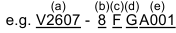
(a) V2607: Engine Model Name
(b) 8: Engine Series (07 series)
(c) C: Production Year (2015)
(d) L: Production Month (April)
(e) A001: Lot Number: (0001 to 9999 or A001 to Z999)
[2] E4B ENGINE
[Example: Engine Model Name V2607-CR-TE4-XXXX]
The emission controls previously implemented in various countries to prevent air pollution will be stepped up as Nonroad Emission Standards continue to change. The timing or applicable date of the specific Nonroad Emission regulations depends on the engine output classification.
Over the past several years, KUBOTA has been supplying diesel engines that comply with regulations in the respective countries affected by Nonroad Emission regulations. For KUBOTA Engines, E4B will be the designation that identifies engine models affected by the next emission phase (See the table below).
When servicing or repairing ###-E4B series engines, use only replacement parts for that specific E4B engine, designated by the appropriate E4B KUBOTA Parts List and perform all maintenance services listed in the appropriate KUBOTA Operator's Manual or in the appropriate E4B KUBOTA Workshop Manual. Use of incorrect replacement parts or replacement parts from other emission level engines (for example: E3B engines), may result in emission levels out of compliance with the original E4B design and EPA or other applicable regulations. Please refer to the emission label located on the engine head cover to identify Output classification and Emission Control Information. E4B engines are identified with "EF" at the end of the Model designation, on the US EPA label. Please note: E4B is not marked on the engine.

| Category (1) | Engine output classification | EU regulation |
| P | From 37 to less than 56 kW | STAGE IIIB |
| N | From 56 to less than 75 kW | STAGE IIIB |
| M | From 75 to less than 130 kW | STAGE IIIB |
| Category (2) | Engine output classification | EPA regulation |
| EF | Less than 19 kW | Tier 4 |
| From 19 to less than 56 kW | Interim Tier 4 | |
| From 56 to less than 75 kW | Interim Tier 4 | |
| From 75 to less than 130 kW | Interim Tier 4 |
(1) EU regulation engine output classification category
(2) "E4B" engines are identified with "EF" at the end of the Model designation, on the US EPA label.
"E4B" designates some Interim Tier 4 / Tier 4 models, depending on engine output classification.
[3] CYLINDER NUMBER

You can see the cylinder numbers of KUBOTA diesel engine in the figure.
The sequence of cylinder numbers is No.1, No.2, No.3 and No.4 and it starts from the gear case side.
MUFFLER FULL ASSEMBLY IDENTIFICATION
[1] PART NUMBER AND SERIAL NUMBER

(1) DPF Muffler Full Assembly Part Number and Serial Number
Diesel Particulate Filter (hereinafter referred to as the "DPF") Muffler Full Assembly Serial Number
The DPF muffler full assembly serial number is an identified number for the DPF muffler full assembly.
It shows the month and year of manufacture as below.
Year of manufacture
| Alphabet or Number | Year | Alphabet or Number | Year |
| 1 | 2001 | F | 2015 |
| 2 | 2002 | G | 2016 |
| 3 | 2003 | H | 2017 |
| 4 | 2004 | J | 2018 |
| 5 | 2005 | K | 2019 |
| 6 | 2006 | L | 2020 |
| 7 | 2007 | M | 2021 |
| 8 | 2008 | N | 2022 |
| 9 | 2009 | P | 2023 |
| A | 2010 | R | 2024 |
| B | 2011 | S | 2025 |
| C | 2012 | T | 2026 |
| D | 2013 | V | 2027 |
| E | 2014 |
Month of manufacture
| Month | DPF Muffler Full Assembly Lot Number | |
| January | A0001 to A9999 | B0001 to BZ999 |
| February | C0001 to C9999 | D0001 to DZ999 |
| March | E0001 to E9999 | F0001 to FZ999 |
| April | G0001 to G9999 | H0001 to HZ999 |
| May | J0001 to J9999 | K0001 to KZ999 |
| June | L0001 to L9999 | M0001 to MZ999 |
| July | N0001 to N9999 | P0001 to PZ999 |
| August | Q0001 to Q9999 | R0001 to RZ999 |
| September | S0001 to S9999 | T0001 to TZ999 |
| October | U0001 to U9999 | V0001 to VZ999 |
| November | W0001 to W9999 | X0001 to XZ999 |
| December | Y0001 to Y9999 | Z0001 to ZZ999 |
* Alphabetical letters "I" and "O" are not used.
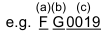
(a) Year: F Indicates 2015
(b) Month: G or H Indicates April
(c) Lot Number: (0001 to 9999 or A001 to Z999)
Diesel Particulate Filter (hereinafter referred to as the "DPF") Muffler Full Assembly Serial Number
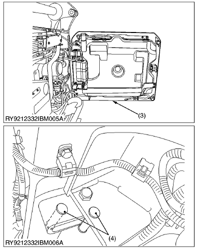
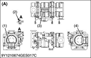
You must keep the records of the filter comp (DPF) part number and serial number (3) and catalyst (DOC) part number and serial number (4) before you remove the DPF for cleaning.
(1) DPF Muffler Assy Part Number and Serial Number
(2) DPF Muffler Full Assy Part Number and Serial Number
(3) Filter Comp (DPF) Part Number and Serial Number
(4) Catalyst (DOC) Part Number and Serial Number
(A) V2607-CR-TE4
V3307-CR-TE4
GENERAL PRECAUTIONS
Whenever performing maintenance on the machine, always read the Safety Precautions in this manual and the Operator's Manual carefully, become familiar with them and perform the work safely.
Before performing any maintenance on the machine, make sure it is sufficiently clean and choose a sufficiently clean location to perform any disassembly.
Before performing maintenance on the machine, always disconnect the negative battery cable first.
Whenever a special tool is required, use the special tool that KUBOTA recommends. Make any special tools that are not used very frequently according to the diagrams in this manual.
Always use genuine KUBOTA parts to maintain the performance and safety characteristics of the machine.
Plumber's Tape

• Wrap plumber's tape on the threads before tightening taper couplings. After wrapping (2 wraps) the plumber's tape, tighten to the specified torque. Once the coupling is tightened, do not loosen it as this will cause an oil leak.
(1) Plumber's Tape
(2) External Thread
(3) Internal Thread
(4) Gap
(5) Leave 1 to 2 Threads
O-Ring

- Clean the groove the O-ring goes in and remove any burrs. Apply grease on the O-ring when inserting it in the groove. (Except floating seals)
- When putting the O-ring in the groove, be careful as it is easy at the very end to twist the O-ring against the inside of the groove. If it gets twisted, roll it gently with your fingertip to untwist it.
(1) O-Ring Groove
(2) O-Ring
(3) Check for Burrs
(4) If the Ring Touches This Corner, It Will Twist
Oil Seal

(1) Gasket
(2) Metal Ring
(3) Spring
(4) Main Lip
(5) Grease
(6) Dust Lip
A : Air (Outside)
B : Hydraulic Chamber (Inside)
- Do not face the lip of the oil seal in the wrong direction. Face the main lip toward the material to be sealed.
- After oil seals are replaced, apply grease to the moving parts around the lip to prevent the dry surfaces from wearing against each other when the engine is started. If the seal has a dust lip, fill the gap between the lips with grease.
- As a general rule, use a press to insert the oil seal in place. If that is not possible, use an appropriate tool to gently and evenly tap it into place, taking care that it does not go in at a slant. Press the seal all the way so it seats in the boss.
Floating Seal

(1) Surrounding Surfaces
(2) O-Ring
- Be sure to wipe off any oil from the O-ring or surfaces that touch the O-ring. (For wheel motors, apply a light film)
- When putting an O-ring into a floating seal, make sure the O-ring does not twist.
- Apply a light film of oil to surrounding surfaces when working to get the floating seal with O-ring in place; take care that the surrounding surfaces, O-ring and housing are parallel with each other.
- After getting the seal in place, turn the engine over 2 or 3 revolutions, to both create a film of oil on surrounding surfaces and to properly seat the face of the seal.
Snap Ring Related

(1) Position so the Angled Part Receives the Force
(A) External
(B) Internal
- When installing external or internal snap rings, orient them as shown in the diagram so the angled side faces the direction of force.
Spring Pins

(1) With Lateral Movement
(2) With Rotational Movement
- When driving a spring pin, face the split in the direction that receives the force, as shown in the diagram.
Adhesive

(A) Bolt Through-Hole (Nut)
(B) Pocket Bolt Hold (Capsule Shape, etc.)
(a) Apply Here
(b) Do Not Apply
(c) Drip On
- Clean and dry the area where adhesive will be applied with a solvent so it is free of moisture, oil and dirt.
- Apply adhesive all around the threads of the bolt except the first set of threads at the tip and fill the grooves between the threads. If the threads or the grooves are large, adjust the amount of adhesive accordingly and apply it all around the bolt hole as well.
Tightening Bolts and Nuts

(A) Top/Bottom Alternately
(B) Across Diagonally
(C) Diagonally Across the Center
- Tighten bolts and nuts to their specified torque.
- Tighten nuts and bolts alternately top/bottom(a) (b), left/right so the torque is distributed evenly.
Assembling Hydraulic Hoses
- Tighten to their specified torque.
- Before assembling, wipe the inside of metal fittings clean of any dirt.
- After assembly, put the fitting under normal pressure and check that it does not leak.
Elbow with Male Seat Assembly Procedure
When assembling an elbow with male seat, adhere to the following procedures to prevent deformation of O-rings and leaks.
- Connecting to Valves


- Clean the blow with male seat and the surface of the seal opposite and mount with the lock-nut on top.
- Finger tighten till it touches the washer.
- Positioning


- Turn the mouth of the elbow back so it faces the right direction. (not back over 1 turn)
- Fasten


- Tighten the lock-nut to the specified torque with a wrench.
(1) Lock-Nut
(2) Washer
(3) Seal (O-Ring)
(4) Wrench for Holding
(5) Hose
(6) Torque Wrench for Tightening
Installing and Removing Quick Couplings

(1) Plastic Part
(2) Fitting
- To remove a quick hose coupling, push the fitting in the direction of the arrow and pull on the plastic part in the opposite direction.
- To attach a quick coupler, push it in firmly in the direction of the arrow. Then check that it will not pull off.
Connecting the face sealing (ORS) type hose
 type hose - Step 1")
(1) Protective cap
- Remove the protective cap from the adapter and make sure the O-ring is installed in its groove. (If the O-ring is missing, fit the specified-size in position.)
- Apply oil to the threads of the hose cap nut and the edge that touches the O-ring.
 type hose - Step 2")
- Make sure the mating surface on the hose side is in good contact with the O-ring on the joint side. Make sure it will not come off.
 type hose - Step 3")
- Be sure to tighten the cap nut to the specified torque.
 type hose - Step 4")
 type hose - Step 2")
 type hose - Step 3")
 type hose - Step 4")
HANDLING PRECAUTIONS FOR ELECTRICAL PARTS AND WIRING
Follow the precautions below for handling electrical parts and
- Inspect electrical wiring for damage and/or loose connections.
- Do not alter or rewire any electrical parts or wiring.
- Always remove the negative battery cable first when disconnecting the battery and attach the positive cable first when connecting it.

(1) Battery Cable (-) Side
(2) Battery Cable (+) Side
[1] WIRING
- Tighten wiring terminals securely.

(1) Correct (Tightened Securely)
(2) Incorrect (Poor Contact if Loose)
- Keep wiring away from hazards.

(1) Hazardous Positioning
(2) Wiring Position (Wrong)
(3) Wiring Position (Right)
(4) Hazardous Position
- Immediately repair or replace old or damaged wiring.

(1) Damaged
(2) Torn
(3) Electrical Tape
- Insert grommet securely.

(1) Grommet
(A) Correct
(B) Incorrect
- Clamp wiring securely but do not damage wires with the clamp.

(1) Clamp (Spiral Clamp Around Wire)
(2) Wire
(3) Clamp
(4) Welding Mark
- Clamp wiring so it is not twisted, pulled too tight or sag too much. However, moving parts may require play in the wiring.

(1) Wire
(2) Clamp
(A) Correct
(B) Incorrect
- Do not pinch or bind wiring when installing parts.

(1) Wire
(A) Incorrect
- After wiring, double-check terminal protectors and clamps before connecting battery cables.

(1) Cover (Install Covers Securely)
- Do not modify harnesses. The diameter of wires in each harness is determined after calculating its capacity.
- Modifying harnesses may cause a malfunction or a fire.

(A) Wiring Diagram
(B) Diagram of Modification
(a) Standard Wiring
(b) Modified Wiring
Colors of Wiring
| Color of wiring | Color code | Color of wiring | Color code |
| Black | B | Blue / Green | L/G |
| Green | G | Blue / Orange | L/Or |
| Blue | L | Blue / Red | L/R |
| Pink | P | Blue / White | L/W |
| Red | R | Blue / Yellow | L/Y |
| White | W | Light Green / Blue | Lg/B |
| Yellow | Y | Light Green / Red | Lg/R |
| Brown | Br | Light Green / White | Lg/W |
| Gray | GY | Light Green / Yellow | Lg/Y |
| Light Green | Lg | Orange / White | Or/W |
| Orange | Or | Pink / White | P/W |
| Sky Blue | Sb | Pink / Blue | P/L |
| Black / Green | B/G | Red / Black | R/B |
| Black / Blue | B/L | Red / Green | R/G |
| Black / Pink | B/P | Red / Blue | R/L |
| Black / Violet | B/V | Red / White | R/W |
| Black / Red | B/R | Red / Yellow | R/Y |
| Black / White | B/W | Violet / White | V/W |
| Black / Yellow | B/Y | White / Black | B/W |
| Brown / Black | Br/B | White / Green | W/G |
| Brown / Yellow | Br/Y | White / Blue | W/L |
| Brown / Red | Br/R | White / Red | W/R |
| Green / Black | G/B | White / Yellow | W/Y |
| Green / Blue | G/L | Yellow / Black | Y/B |
| Green / Red | G/R | Yellow / Green | Y/G |
| Green / White | G/W | Yellow / Blue | Y/L |
| Green / Yellow | G/Y | Yellow / Red | Y/R |
| Blue / Black | L/B |
(Ex.)
1.25-Y/R means:
1.25: Wire size (mm2)
Y: Base color (yellow)
R: Stripe color (red)
- Do not pull on or step on wires. Also, do not cut wires on burred edges or the like.
- Do not twist or pinch wiring when installing it.

(a) Wire Size (mm 2)
(b) Insulation Base Color
(c) Stripe Color
[2] FUSES
- Always use fuses of the specified capacity. Never use over or undersized fuses.
- Never use copper or steel wire in place of a fuse.
- Do not install accessories such as work lights, radios, etc., if your machine does not have an auxiliary circuit.
- Do not install accessories as they will exceed the capacity of fuses.

(1) Fuse
(2) Fusible Link
(3) Slow-Blow Fuse
[3] CONNECTOR
Connectors
The terminals of female connector are numbered from #1 on the top right when facing it.
Male terminals are numbered from #1 on the top left.

(A) Female connector terminals
(B) Male connector terminals
- Press the lock to disconnect locking connectors.

(A) Push
- Hold the connectors when separating them.
- Do not pull on the wire harness to separate the connectors.

(A) Correct
(B) Incorrect
Pull on the harness from the connector and make sure the harness does not come off. (Pull with 3 kgf (30 N, 7 lbf) or less of force)

(A) Pull
(B) Loosened Crimping
- Straighten bent prongs and make sure none are sticking out or missing.
- Remove corrosion from terminals with sandpaper.

(1) Missing Terminal
(2) Bent Prong
(3) Sandpaper
(4) Corrosion
- Do not touch the terminals of connectors with bare hands.

(A) Do not touch
- Female connectors must not be spread too far open

(A) Correct
(B) Incorrect
- The plastic covers of connectors must cover them completely.

(1) Cover
(A) Correct
(B) Incorrect
[4] WASHING THE MACHINE WITH A HIGH-PRESSURE WASHER
Using a high-pressure washer incorrectly can lead to personal injury and/or damage, break or cause parts of the machine to fail, so use the power washer properly according to its operator's manual and labels.
- Stand at least 2.0 meters from the machine and adjust the nozzle for a wide spray so it does not cause any damage. If you blast the machine with water or wash it from too close a distance,
- It may cause a fire due to damaged or cuts in the insulation of electrical wiring.
- An injury may result if hydraulic oil gushes out under high pressure, due to damaged hydraulic hoses.
- It may damage, break or cause parts of the machine to fail.
(Ex.)
(1) Stickers or labels may come off
(2) Electrical parts or the engine may fail due to water in them.
(3) Damage glass, resins, etc. or the rubber of oil seals.
(4) Tear off paint or the film from plating

(1) Do Not Blast with Water
(2) Never Wash from Too Close
(A) Blasting
(B) Wide Spray
(C) Less Than 2.0 m (80 in.)
(D) Over 2.0 m (80 in.)
TIGHTENING TORQUES
[1] GENERAL USE SCREWS, BOLTS AND NUTS
Screws, bolts and nuts whose tightening torques are not specified in this Workshop Manual should be tightened according to the table below.
| Indication on top of bolt |  No-grade or 4T No-grade or 4T |  7T 7T |  9T 9T | 10.9 | ||||||||||||||
| Indication on top of nut |  No-grade or 4T No-grade or 4T |  6T | ||||||||||||||||
| Material of opponent part | Steel | Aluminum | Steel | Aluminum | Steel | Steel | ||||||||||||
| Unit | N·m | kgf·m | lbf·ft | N·m | kgf·m | lbf·ft | N·m | kgf·m | lbf·ft | N·m | kgf·m | lbf·ft | N·m | kgf·m | lbf·ft | N·m | kgf·m | lbf·ft |
| M6 | 7.9 to 9.3 | 0.8 to 0.95 | 5.8 to 6.8 | 7.9 to 8.8 | 0.8 to 0.9 | 5.8 to 6.5 | 9.81 to 11.2 | 1.0 to 1.15 | 7.24 to 8.31 | 7.9 to 8.8 | 0.8 to 0.9 | 5.8 to 6.5 | 12.3 to 14.2 | 1.25 to 1.45 | 9.05 to 10.4 | – | – | – |
| M8 | 18 to 20 | 1.8 to 2.1 | 13 to 15 | 17 to 19 | 1.7 to 2.0 | 13 to 14 | 24 to 27 | 2.4 to 2.8 | 18 to 20 | 18 to 20 | 1.8 to 2.1 | 13 to 15 | 30 to 34 | 3.0 to 3.5 | 22 to 25 | – | – | – |
| M10 | 40 to 45 | 4.0 to 4.6 | 29 to 33 | 32 to 34 | 3.2 to 3.5 | 24 to 25 | 48 to 55 | 4.9 to 5.7 | 36 to 41 | 40 to 44 | 4.0 to 4.5 | 29 to 32 | 61 to 70 | 6.2 to 7.2 | 45 to 52 | – | – | – |
| M12 | 63 to 72 | 6.4 to 7.4 | 47 to 53 | – | – | – | 78 to 90 | 7.9 to 9.2 | 58 to 66 | 63 to 72 | 6.4 to 7.4 | 47 to 53 | 103 to 117 | 10.5 to 12 | 76 to 86.7 | – | – | – |
| M14 | 108 to 125 | 11 to 12.8 | 79.6 to 92.5 | – | – | – | 124 to 147 | 12.6 to 15 | 91.2 to 108 | – | – | – | 167 to 196 | 17 to 20 | 123 to 144 | – | – | – |
| M16 | 167 to 191 | 17 to 19.5 | 123 to 141 | – | – | – | 197 to 225 | 20 to 23 | 145 to 166 | – | – | – | 260 to 304 | 26.5 to 31 | 192 to 224 | – | – | – |
| M18 | 246 to 284 | 25 to 29 | 181 to 209 | – | – | – | 275 to 318 | 28 to 32.5 | 203 to 235 | – | – | – | 344 to 402 | 35 to 41 | 254 to 296 | – | – | – |
| M20 | 334 to 392 | 34 to 40 | 246 to 289 | – | – | – | 368 to 431 | 37.5 to 44 | 272 to 318 | – | – | – | 520 to 569 | 53.0 to 58.0 | 384 to 420 | – | – | – |
[2] STUD BOLTS
| Material of opponent part | Steel | Aluminum | ||||
| Unit | N·m | kgf·m | lbf·ft | N·m | kgf·m | lbf·ft |
| M8 | 12 to 15 | 1.2 to 1.6 | 8.7 to 11 | 8.9 to 11 | 0.90 to 1.2 | 6.5 to 8.6 |
| M10 | 25 to 31 | 2.5 to 3.2 | 18 to 23 | 20 to 25 | 2.0 to 2.6 | 15 to 18 |
| M12 | 30 to 49 | 3.0 to 5.0 | 22 to 36 | 31 | 3.2 | 23 |
| M14 | 62 to 73 | 6.3 to 7.5 | 46 to 54 | – | – | – |
| M16 | 98.1 to 112 | 10.0 to 11.5 | 72.4 to 83.1 | – | – | – |
| M18 | 172 to 201 | 17.5 to 20.5 | 127 to 148 | – | – | – |
[3] TORQUE FOR HYDRAULIC HOSE FITTINGS
(1) Torque for Hydraulic Hose Fittings
Union Nuts

(1) Nuts
| Tightening torque | 1/8 | 7.8 to 11.8 N·m 0.8 to 1.2 kgf·m 5.7 to 8.7 lbf·ft |
| 1/4 | 24.5 to 29.2 N·m 2.5 to 3.0 kgf·m 18.1 to 21.7 lbf·ft | |
| 3/8 | 37.2 to 42.1 N·m 3.8 to 4.3 kgf·m 27.5 to 31.1 lbf·ft | |
| 1/2 | 58.8 to 63.7 N·m 6.0 to 6.5 kgf·m 43.4 to 47 lbf·ft | |
| 3/4 | 112 to 123 N·m 11.4 to 13 kgf·m 82.5 to 94 lbf·ft |
Unify (UNF)
")
| Tightening torque | 7/16-20UNF | to 21 N·m1.9 to 2.1 kgf·m |
| 9/16-18UNF | to 36 N·m3.3 to 3.7 kgf·m | |
| 3/4-16UNF | to 62 N·m5.7 to 6.3 kgf·m | |
| 7/8-14UNF | to 82 N·m7.5 to 8.4 kgf·m | |
| 1-1/16-12UNF | to 123 N·m to 12.5 kgf·m |
Fase Seal Type (ORS)
")
(1) O-Ring
| Tightening torque | -3/16 -12UN | to 165 N·m to 16.8 kgf·m to 121 lbf·ft |
(2) Torques of Lock-Nuts for Elbows with Male Seats and Adaptors with O-rings (Straight Threads)

(1) Lock-Nut
(2) Washer
(3) Seal (O-Ring)
| Tightening torque | 1/4 | 24.5 to 29.4 N·m 2.5 to 3.0 kgf·m 18.1 to 21.7 lbf·ft |
| 1/2 | 58.8 to 63.7 N·m 6.0 to 6.5 kgf·m 43.4 to 47.0 lbf·ft | |
| 3/4 | 117.6 to 127.4 N·m 12.0 to 13.0 kgf·m 86.8 to 94.0 lbf·ft | |
| 7/16-20UNF | 19.0 to 21.0 N·m 1.9 to 2.1 kgf·m 14 to 15 lbf·ft | |
| 9/16-18UNF | 32.0 to 36.0 N·m 3.3 to 3.7 kgf·m 24.1 to 27.0 lbf·ft | |
| 3/4-16UNF | 56.0 to 62.0 N·m 5.7 to 6.3 kgf·m 42.1 to 46.5 lbf·ft | |
| 7/8-14UNF | 74.0 to 82.0 N·m 7.6 to 8.4 kgf·m 55.5 to 61.6 lbf·ft | |
| 1.1/16-12UN | 112.0 to 123.0 N·m 11.4 to 12.6 kgf·m 84.2 to 92.4 lbf·ft |
(3) Torque for Tapering Adaptors

(1) Taper
| Tightening torque | 1/8 | 19.6 to 29.4 N·m 2.0 to 3.0 kgf·m 14.5 to 21.7 lbf·ft |
| 1/4 | 36.6 to 44.1 N·m 3.7 to 4.5 kgf·m 26.8 to 32.5 lbf·ft | |
| 3/8 | 68.6 to 73.5 N·m 7.0 to 7.5 kgf·m 50.6 to 54.2 lbf·ft | |
| 1/2 | 83.4 to 88.3 N·m 8.5 to 9.0 kgf·m 61.5 to 65.1 lbf·ft | |
| 3/4 | 166.6 to 181.3 N·m to 18.5 kgf·m to 133.8 lbf·ft |
Documents / ResourcesDownload manual
Here you can download full pdf version of manual, it may contain additional safety instructions, warranty information, FCC rules, etc.
Advertisement


Need help?
Do you have a question about the WSM SSV65 and is the answer not in the manual?
Questions and answers