Lab.gruppen FP+ Series, FP 14000 / 9000 / 7000 / 4000 / 10000Q / 6000Q Manual
- Quick start manual (123 pages) ,
- Operation manual (40 pages) ,
- Operation manual (37 pages)
Advertisement
Welcome
Introduction
We are confident that you will be pleased with the performance, configuration flexibility, reliability, and long-term durability offered by the FP+ Series products.
This manual provides a comprehensive guide to the features and functionality of FP+ Series amplifiers. Please read through it to become fully acquainted with the many configuration options and multiple layers of protection circuitry. To facilitate timely installation and use of this FP+ Series product, we have included a Quick Guide Overview. This brief summary, in conjunction with Installation, contains the basic information needed to safely install the amplifier and place it in service. However, we highly recommend reading through this manual in its entirety, beginning with Main Features and Technologies and continuing through Operation and Performance. As you become thoroughly familiar with all aspects of operation, you may learn of features or options that will affect your choices on amplifier modes or loudspeaker system configuration.
The Lab.gruppen FP+ Series builds on the foundation of the road-tested fP Series, with the same sonic signature – powerful, tight bass and transparent high frequency response. In addition, the FP+ Series amplifiers establish new benchmarks for extremely high power and channel density, and also offer the benefits of remote computer monitoring and control via the NomadLink network.
Main Features
The FP+ Series incorporates a number of sophisticated technologies – many of them proprietary to Lab.gruppen – to ensure the best possible performance and many years of reliable operation. Familiarizing yourself with these technologies will prove invaluable in setting up and optimizing your loudspeaker system.
Patented Class TD amplifier and Regulated Switch Mode Power Supply (R.SMPS)
Lab.gruppen's patented Class TD technology combines the exceptional efficiency of a Class D amplifier with the high sonic quality associated with Class B designs. Class TD also incorporates the same basic concepts behind Class H designs, but here they are refined and pushed to a higher level to achieve greater efficiency.
The Class TD output sections work in concert with Lab.gruppen's unique, Regulated Switch Mode Power Supply (R.SMPS) to create a superior overall power amplifier topology. R.SMPS ensures stable, full output power over an extremely wide range of mains voltage levels. Sagging or fluctuating mains voltage will not affect the power output delivered to the loudspeakers.
Amplifier gain
For greater flexibility in system integration, FP+ Series amplifiers allow gain adjustment from +23 dB to +44 dB in 3 dB steps. This feature accommodates any combination of input device and loudspeaker type. For example, if the input signal is weak, the gain can be boosted to maintain maximum power output while avoiding a poor signal-to-noise ratio. This gain adjustment feature makes it easier to achieve an optimal balance between headroom and noise floor.
Voltage Peak Limiter (VPL)
The Voltage Peak Limiter (VPL) feature allows user adjustments that determine maximum voltage output, thus matching the amplifier to the connected speaker load. Regardless of load impedance, the VPL feature can be set to ensure that neither temperature nor current limitations are exceeded before reaching the desired voltage threshold.
Protection and performance optimization
Appropriate and reliable power amplification is vital to any audio system. Inadequate or faulty power amplification could cause damage to the loudspeakers, or in some cases to the power amplifiers themselves. To prevent any damage or costly service interruptions, FP+ Series amplifiers offer advanced features to protect both internal circuits and any connected loads. These features even protect the mains fuse that, in extreme cases, could be overloaded.
Following are short descriptions of standard built-in FP+ Series protection features:
- CPL, (Current Peak Limiter) ensures that the amplifier's output does not exceed the safe current handling parameters of amplifier components.
- Temperature protection ensures that the amplifier will not be damaged by exceeding thermal limits.
- PAL, (Power Average Limiter) limits the maximum average power consumption according to the power supply and mains-breaker capabilities.
- VHF, (Very High Frequency) protection circuits mute the output of the amplifier when nondynamic continuous signals above 10 kHz are detected.
- DC protection ensures destructive DC signals will not appear at the amplifier outputs. If such conditions occur an internal fuse opens and fault indication is displayed.
- Low-impedance (short circuit) protection provides a fault warning indication and shuts down the output stage when, for example, an input signal is present and a malfunctioning cable or driver is short circuiting the output.
- High-impedance warning reports an alert when, at the same time, output signal is high and no current draw is measured. This situation might occur when no speakers are connected, or when a driver is blown.
- Low inrush current ensures that the mains breaker will not trip when several power amplifiers are turned on simultaneously.
NomadLink / Ethernet control and monitoring network
The NomadLink network allows easy setup, monitoring, and control of FP+ Series power amplifiers and other Lab.gruppen NomadLink-enabled amplifiers. The patented network topology provides automatic detection and addressing of multiple amplifiers, and is controlled from a PC via the optional NLB 60E NomadLink Bridge & Network Controller using standard TCP/IP communication. Phantom powering through the network cables enables the software to detect devices that are not currently turned on or connected to the mains. This ensures very high reliability and redundancy levels while allowing connected amplifiers to remain on standby with no power consumption.
Cable connections can be daisy-chained for easier system setup. This also reduces total component costs, simplifies installation, and makes daily operation more convenient. There is no need to create a star topology using many switches as with, for example, an Ethernet system. Individual amplifier addresses do not need to be manually entered; you will automatically know where an individual amplifier resides in the network.
A daisy chain network loop, in combination with the automatic addressing of devices, enables Lab.gruppen's proprietary DeviceControl software to automatically create a precise picture of all connected devices and their relative position in the chain. By quickly creating a clear overview of the entire system configuration, DeviceControl provides flexible control of very large amplifier systems. Set-up time is minimized, and critical information is readily available for monitoring performance and solving problems during operation.
Via NomadLink, you can monitor all metering data as well as all faults and warning indications simultaneously. NomadLink also allows you to remotely control power on and power off, as well as engage Mute and Solo functions on individual channels.
Installation
Unpacking
Carefully open the shipping carton and check for any noticeable damage. Every Lab.gruppen amplifier is tested and inspected before leaving the factory and should arrive in perfect condition. If any damage is discovered, please notify the shipping company immediately. Only the consignee may institute a claim with the carrier for damage incurred during shipping. Save the carton and packing materials for the carrier's inspection. Should you ever need to ship the amplifier, always use the original packaging materials.
Mounting
Free airflow from front-to-rear of the amplifier must be possible. Therefore, no doors or rack-lids should be mounted in front of or behind the amplifiers.
Amplifiers may be stacked directly on top of each other. There is no need for spacing in between units, though this might enable more convenient installation of cabling on the rear panel.
It is recommended that rear supports be mounted for maximum long-term stability. Rear support brackets are included.
Figure 1a: Rear support mounting hardware

Figure 1b: Use washer for fixed installation

Figure 1c: Use tube for slide-on installation.

Cooling
The amplifier uses a forced-air cooling system with air flow from front to rear, maintaining a low operating temperature within defined limits. Front-to-rear airflow is preferred as cooler air is present at the front in nearly all applications. (This allows higher continuous power levels without encountering thermal problems.) Never attempt to reverse the airflow. The amplifier modules require a pressure chamber between the fans and heatsink, and this effect functions only in one direction.
Make sure that there is an adequate air supply in front of the amplifier, and that the rear of the amplifier has sufficient space to allow the exhaust to escape. If the amplifier is rack-mounted, do not use covers or doors on the front or rear of the rack.
Should a heat sink overheat, the temperature sensing circuits will mute the overheating channel. If the power supply overheats, another sensing circuit will mute all output channels until the power supply cools to safe operating temperature. An early warning before shut down will be indicated on the front panel LEDs, and a warning will be sent through the NomadLink network.
Always make sure that the dust-filters behind the detachable front panel are clean to ensure maximum possible airflow.
Note: If the amplifier malfunctions due to dirty dust filters, any required repairs are not covered by the warranty.
Operating voltage
The label placed to the right of the mains cable on the rear of the amplifier indicates the AC mains voltage for which the amplifier is wired and approved: 115 V or 230 V. Connect the power cable only to the AC source type referred to on the label. The warranty will not cover damage caused by connecting to an incorrect type of AC mains.
Lab.gruppen switch mode amplifiers use primary switching. Because the mains power is rectified directly in front of the transformer, the amplifier is insensitive to mains frequency. It may be connected to 50 or 60 Hz sources, and actually will operate on line frequencies from DC to 400 Hz.
If the power plug mounted at the factory is not appropriate for your country, it can be removed and the proper connector wired in its place as follows:
| BLACK or BROWN | LIVE |
| WHITE or BLUE | NEUTRAL |
| GREEN or GREEN/YELLOW | EARTH(GROUND) |
If you are not 100% confident of your competence to replace the mains plug, engage qualified personnel to do the job.
Once a suitable AC supply is connected, the amplifier can be turned on using the front panel power switch. The amplifier then goes through a soft-start sequence as it self-checks its circuits. The fans will blow at high speed before dropping to idle, and the "power" LED will illuminate.
Inrush power is controlled and limited during "softstart", enabling multiple amplifiers to be powered up simultaneously.
Grounding
There is no ground lift switch or terminal on the FP+ Series amplifiers. The signal ground is always floating, via a resistor, to chassis and therefore the grounding system is automatic.
In the interests of safety, never disconnect the earth (ground) pin on the AC power cord.
Use balanced input connections to avoid hum and interference.
Quick Guide Overview
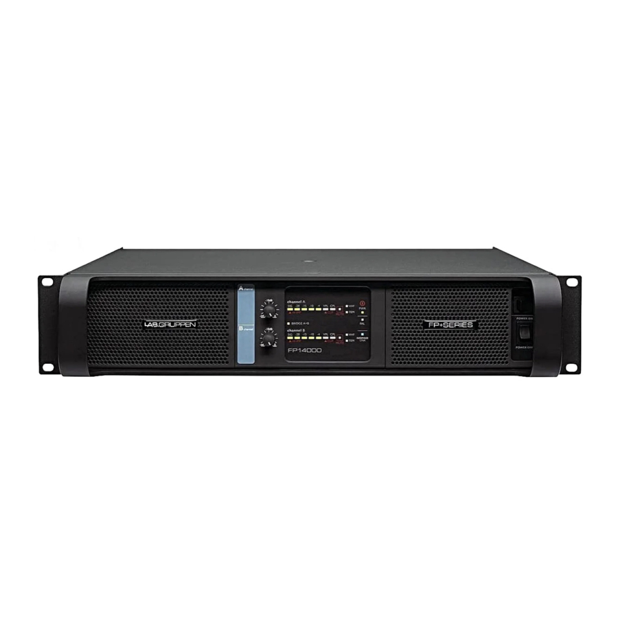
Front-Panel overview

The amplifier's front panel presents the performance and fault condition indicators, power and remote switches, and a removable dust-filter cover. Level potentiometers provide individual attenuation for the amplifier channels. Range is 0 dB to - infinity. (The 12 o'clock position indicates -10 dB attenuation.) A convenient label strip with writing surface is provided adjacent to each level potentiometer.
To remove the dust-filter covers, loosen the thumbscrews located underneath the front handles. This allows removal of the dust-filters for cleaning. The covers may be made "tamper resistant" by replacing the thumbscrews with Philips head or safety Torx screw. Thread size is M3. Note: The amplifier never should be operated without the dust-filters in place.
Power on/off and remote switch
The Power on/off switch is located on the right side. A second switch, labeled "REMOTE," is above the Power switch. When the Remote switch is on (with mains connected and power on/off switch on), the yellow LED above it will illuminate indicating that external power on/off commands from the NomadLink network connection will switch the amplifier on or off. When Remote is activated the amplifier will not switch on until a "Power On" command is received from the network. When the remote switch is off, it is not possible to switch amplifier power on or off using NomadLink network control.
Front-panel LED's
The front-panel LED area includes the following indicators per channel:
Figure 2a: Front panel LED field (per-channel)

- VHF - Very High Frequency protection active (output muted) (Yellow constant)
- TEM - Temperature warning (Yellow flashing)
- TEM - Temperature mute (Yellow constant)
- MUTE - Channel muted via NomadLink network or due to a fault condition (Red)
- CPL - Current Peak Limiter (CPL) active (Orange flashing)
- CPL - (Orange constant with output muted): Low impedance / short circuit detection fault
- VPL - Voltage Peak Limiter (VPL) active
- SIG - Signal levels - 40 dB (Sig) to –4 dB
- Hi-Imp - High-impedance/open load detected (Orange)
- Bridge - Bridge mode operation (Yellow)
Note: When no VPL, CPL or PAL indicators are illuminated, and the VPL DIP-switch is set to maximum at the specified nominal load, the amplifier channel is able to deliver maximum rated output power
Figure 2b: Front panel global LED field

When the network is connected, the blue NomadLink LED will illuminate even when mains power is not connected. NomadLink receives phantom power from the network as supplied by the NLB 60E.
Rear-Panel overview

Network and Configuration section
Note: Four-channel model shown. Two-channel versions have VPL and Bridge Mode switches for channels A and B only. All models have different VPL values. Functions are otherwise identical.
Figure 2d: Rear panel DIP-switch field

The DIP-switch features
The following features may be adjusted using the DIP-switches on the rear panel of the amplifier. Gain – Globally set for all channels, from +23 dB to +44 dB in 3 dB steps.
Option active – Not currently implemented.
Fan Masked – When on, engages the intelligent fan feature; fan speed is lowered when no signal is present.
Bridge A+B and C+D – Switches the channel pairs into bridge mode operation An automatic -6 dB gain compensation is applied.
VPL – The Voltage Peak Limiter provides optimum peak voltage settings for each channel. Level selections vary by model within the FP+ Series.
Mode – Select VPL mode to either Hard or Soft operation. For channels driving sub-woofers and low-frequency drivers, it is recommended to use the Hard setting for optimal operation. For mid- and high- frequency drivers, always select Soft.

Input and Output connectors
All FP+ Series amplifiers are equipped with balanced XLR-F input connectors. two-channel models also offer parallel ("loop-thru") XLR-M output connectors for daisychaining multiple amplifiers from the same signal source.
All FP+ Series amplifiers except the FP 9000, FP 13000 and FP 14000 offer a choice of either binding post (BP) or Neutrikc NL4FC Speakon output connectors (SP). The FP 9000, FP 13000 and FP 14000 are offered with BP connectors only as the potential maximum output current exceeds the recommended limits for the Speakon connectors.
For specific configuration and wiring information.
Figure 2e: Two- and four-channel input connector configurations

NomadLink / Ethernet network setup
The amplifi er includes, as a standard feature, internal facilities for the NomadLink monitoring and control network. All features of the NomadLink network are accessible via a PC running Lab.gruppen's proprietary DeviceControl software. A single rackspace NLB 60E NomadLink Bridge & Network Controller accepts the TCP/IP data stream from the computer and converts it to the NomadLink protocols. Even when no computer is connected, the NLB 60E can initiate stand-alone power on/off and muting functions, as well as report any fault or warning conditions.
The PC is connected to the NLB 60E using a standard Ethernet interface and a crossed Cat-5 cable (peer-to-peer setup). If a HUB or switch is in the network, standard "straight" Cat-5 cables must be used. The front and rear Ethernet connections on the NLB 60E can be used individually, but only one PC at a time running DeviceControl can access the subnet.
Note: Many newer laptop computers will allow peer-to-peer connection with the NLB 60E using a standard "straight" Cat-5 cable instead of a crossed Cat-5 cable.
The default fi xed TCP/IP address of the NLB 60E is 192.168.1.166. The subnet mask is 255.255.255.0. For further details, please refer to instructions supplied with the NLB 60E unit.
Figure 2f:

The NomadLink connections use standard "straight" Cat-5/RJ45 equipped cables. For a safer mechanical connection it is possible to use Neutrik EtherCon "XLR-type" housings on the cables.
Note: US National Differences cl.16.3 requires that NomadLink network cables must be rated VW-1.
The OUT port from the NLB 60E must be connected to the IN port of the fi rst amplifi er. The OUT port from the fi rst amplifi er in turn connects to the next amplifi er's IN port to form a daisy-chain The OUT port on the last amplifi er is connected to the IN port on the NLB 60E to close the loop.
Note: There are electrical limitations to cable lengths on a NomadLink network, both in terms of total cable length in the loop and between any two devices. Read the Operation and Performance chapter in this manual, or the instructions supplied with the NLB 60E, to ensure the network is confi gured within these parameters.
Tip: Although the network will function as an open loop under most circumstances, it is strongly recommended that the loop be closed by connecting the last amplifi er's OUT port to the NLB 60E's IN port. Doing so will improve redundancy and communication speed.
External contact closures and 24 V low/high triggers can be connected to the GPI connectors on the NLB 60E for control of fi re-alarm systems or external power sequencers. For more details read the instructions supplied with the NLB 60E.
Operation and Performance
Introduction
The following sections provide comprehensive information on amplifier connection, setup, operation, and performance. The detailed information included here is essential to realizing the full functionality of the FP+ Series amplifiers.
Operation precautions
- Make sure that the Power switch and the Remote switch on the amplifier front panel are set to "off" before making any input, output or network connections, and also before manipulating the DIP-switches on the rear panel.
- Make sure that the AC mains voltage is correct and matches the voltage printed on the rear panel of the amplifier (115 V or 230 V).
- Make sure that no signal is present at the input to the amplifier when powering up. An input signal could produce an unintentionally loud initial volume from the speakers.
Signal flow and headroom
Signal flow blocks
All FP+ Series amplifiers have the same signal flow, and the same feature sets. The only internal differences are in the maximum output current per channel and VPL settings.
The input stage of all FP+ Series amplifiers has a high sensitivity to provide ample system headroom. This in effect means that the input stage is almost impossible to clip.
Overall amplifier input gain is adjusted using the input stage DIP-switches. Please note that the gain setting is global, affecting all channels. Following the input stage, the dedicated level control on each channel allows signal attenuation from 0 dB to minus infinity.
The Current Peak Limiter (CPL) section dynamically limits the input signal based on three parameters: sensed current level, feedback from the output stage, and sensed voltage clip from the VPL (and output amplifier voltage clip if "Soft Clip" is activated). This ensures that power output is maintained within the design limits of the amplifier.
The adjustable Voltage Peak Limiter (VPL) sets the maximum output voltage and therefore also the maximum output power. Eight different voltage stages are available using the DIP-switches on the rear panel of all models, except the FP 9000 and FP 4000 that both have seven stages and the FP 6000Q which provides six voltage stages.
The sophisticated output section monitors faults and generates appropriate warnings, which are displayed on the amplifier front panel and transmitted through the NomadLink network. These alerts allow the operator to adjust system settings and thereby avoid problems. In the rare event that conditions are extraordinarily severe, the amplifier will shut down until the fault or problem setting has been rectified or adjusted. These sensing circuits are also employed to feed back voltage and current level information, via a side chain, to the limiters. Sensing circuits also transmit local amplifier module temperature and power supply temperature to the appropriate protection mechanisms. Read the Protection, Faults and Warnings section for further details.

Headroom, sensitivity and VPL / Gain settings
The input amplifier and limiter system is designed to accommodate extremes of performance. Typically, exceeding maximum input by much as +10 dB will only result in a 1% increase in distortion. The following schematics illustrate how the adjustable VPL and Gain circuitry affect input sensitivity and output power.
The tables to the left of the illustration 7.3.2 below show input sensitivity for a FP 13000 with a 2 ohm load and 195 V peak (max.) and 54 V peak (min.) respectively for the eight different gain stages between +23 dB and +44 dB. The resulting output power is displayed in dBu, Vrms and watts in the tables to the far right. Complete input sensitivity tables for all VPL and Gain settings for all FP+ Series models can be found at www.labgruppen.com.
The headroom available through the input stage to the clip limiter is shown by the dotted lines as +10 dB at 195 V peak and +16.1 dB at 54 V peak. These lines illustrate the additional signal level that can be accepted at the input before any significant distortion will appear at the input stage.
Note: If you use the level potentiometer in the signal chain to reduce the level by an amount greater than the headroom relative to input sensitivity, AND you drive the amplifier to clip level, you are in danger of clipping the input stage before the current or voltage peak limiters are activated.
Note: When bridging two channels, you must add +6 dB to the input sensitivity to achieve maximum output voltage due to the automatic -6 dB gain compensation inserted by the amplifier.
Figure 3b: FP 13000 VPL and GAIN settings

Audio Input and Output connections
Balanced Input connections
Figure 3.1a: Audio inputs and loop-thru

Figure 3.1b: Audio inputs - four-channel models

The XLR input connectors are electronically balanced, and wired according to the IEC 268 standard (pin 2 = hot). XLR input connectors should be wired as follows:
Pin 1 Ground/shield
Pin 2 Hot (+)
Pin 3 Cold (-)
Figure 3c: Balanced XLR wiring schematic

Note:When linking the same source signal to several input channels, be aware that there is a limit to the number of channels an output source can "drive". A typical output source (e.g. a DSP crossover unit) can drive up to four amplifier channels before external line-drivers might be required to buffer the signal.
Unbalanced Input connections
Figure 3d: Unbalanced XLR wiring schematic

To connect an input to an unbalanced source, it is possible to connect pins 1 and 3 in the XLR plug at the amplifier end of the cable. However, a better method is to connect pin 3 to the shield at the source end of the cable, as this usually results in better hum and noise rejection. Balanced input connections are recommended whenever possible.
Speakon Output connections
Refer to the instructions in this section if your amplifier is equipped with the Speakon output connectors.
Figure 3.1c: Speakon outputs - two-channel

Figure 3.1d: Speakon outputs - four-channel

Two-channel amplifiers – Two-channel amplifiers are wired in the following manner. The right Speakon connector, Channel A+B, provides outputs for both Channel
A and Channel B. This output is useful when wiring the amplifier for bridged mono operation. The left Speakon connector provides an output for Channel B only.
Connect the + and – loudspeaker cables as shown in the illustrations below.
Figure 3e: Speakon wiring schematic

Four-channel amplifiers – Additional connectors are provided for Channel C and Channel D. Channel C functions as Channel A above, and Channel D as Channel B above.
Binding Post (BP) Output connectors
Refer to the instructions in this section if your amplifier is equipped with Binding Post output connectors.
 Output connectors - Part 1")
 Output connectors - Part 2")
Connect the positive (+) loudspeaker cable to the positive (+) red terminals. Connect the negative (-) loudspeaker cable to the negative (-) black terminals.
For bridge mode, connect the positive (+) terminal on Channel A to the positive (+) loudspeaker cable and the negative (-) terminal on Channel B to the negative (-) loudspeaker cable.
Channels C and D on four-channel versions are connected in the same manner. For bridge mode, connect the positive (+) terminal on Channel C to the positive (+) loudspeaker cable and the negative (-) terminal on Channel D to the negative (-) loudspeaker cable.
The outputs on all FP+ Series amplifiers produce high voltage. Do not connect or disconnect the loudspeaker cables while the mains power is on. Never operate the amplifier with any portion of bare loudspeaker wire exposed. Also, attach the safety cover (4-channel Speakon versions only) on the speaker terminals for safe operation and to comply with electrical product approvals.
Note: Never connect an output terminal to ground, or to any other input or output. Observe relative loudspeaker polarity: loudspeakers connected in reverse polarity will exhibit degraded performance, particularly in bass frequencies, and may be damaged as a consequence. Note: Use a high-quality stranded loudspeaker cable, and keep cable runs as short as possible.
Output bridge mode
It is possible to bridge channels in two-channel versions, or in pairs of two (A+B and C+D) in four-channel versions. When bridged, the input source must be connected to input A (A+B) or C (C+D) respectively. Output speaker cables must be connected to the plus pole on channel A or C and the minus pole on B or D.
The main benefit of bridging the output is a doubling of output voltage. Bridging can be used to turn a four-channel FP 10000Q amplifier, for example into a threechannel amplifier with 2 x 1300 W and 1 x 4200 W at 8 ohms or 2 x 2100 W and 1 x 5000 W at 4 ohms Most power amplifier designs, when bridged, automatically introduce a +6 dB input gain boost which can lead the user to conclude that said amplifier delivers "more than double the power" when in bridge mode. This is clearly not the case, as the gain boost artificially enhances perceived power at the cost of headroom. The FP+ Series amplifiers work on globally set constant gain, and automatically compensate the input gain by -6 dB. For example, if the amplifier is configured in a three-channel mode, then the selected gain is maintained from input to output on all channels.
Amplifier Gain
All FP+ Series amplifiers feature adjustable input gain. This versatility enables the amplifier to accommodate a multitude of system configurations with various input sources and speaker layouts. Amplifier gain is set globally for all channels. The range is +23 dB to +44 dB in 3 dB steps. Individual channel fine level adjustment is available using the potentiometers on the front panel.
The unique adjustable input gain feature of the FP+ Series makes it easier to attain the optimum balance between headroom and signal-to-noise ratio in the signal path. A weak signal at the input might require the gain to be raised in order to achieve maximum output power with the lowest signal-to-noise ratio. A "hot" input signal, however, would require a lowering of the gain to avoid sending the amplifier into Voltage or Current clipping. See Appendix to review the table containing Gain versus VPL setting implications for input sensitivity and output power. Bridge mode operation automatically compensates by -6 dB, keeping all channels at the same gain.
Channel gain/level (front-panel pots)
Individual channel gain (level) may be adjusted using the potentiometers located on the front panel. Range is from 0 dB to -infinity in 31 steps. The attenuation is logarithmic, with the 12 o'clock position indicating -10 dB.
Note: If the level control is used to attenuate to a lower level than the headroom relative to input sensitivity AND the amplifier input is driven into clip, there is a danger of clipping the input stage before the current or voltage peak limiters are activated.
Amplifier sensitivity
Sensitivity is defined as how many Volts (rms) or dBu (referred to 0.775 Vrms) are required to achieve full (maximum) output power. As the output power varies with the load impedance, 4 ohms is usually the common reference. Since FP+ Series amplifiers are capable of providing multiple maximum output power levels through use of the VPL feature, many sensitivity calculations may be required for a single amplifier. We recommend use of the DeviceControl software to simplify this process.
DeviceControl's Device View page, used in combination with the DIPswitch settings display, will automatically produce a sensitivity calculation from the given data (VPL, Gain and load).
Output Voltage Peak Limiter (VPL)
Voltage Peak Limiter (VPL) is a unique feature in FP+ Series amplifiers. It is used to select the maximum power available on each output channel. VPL levels are set using the rear-panel DIP-switches; eight level positions are offered on all models except the FP 6000Q, which offers six).
Table 3a: V peak to Vrms tables for the FP+ Series

The values for VPL are displayed as maximum Voltage Peak. To translate Voltage Peak into Vrms, you must divide the Voltage Peak values by 1.41 (see table). The VPL allows you to set the correct maximum output peak power for optimum performance with the connected speakers. The correct setting depends on the system type and the specific load connected to the channel. Since each channel can be configured to deliver either very high voltage peak power OR high current draw at lowimpedances, it is important to set the VPL correctly.
If you choose a lower VPL setting, you only reduce the maximum output voltage. At the same time, this allows more current headroom for low-impedance loads. The amplifier thus runs at higher efficiency, with a significantly reduced risk of going into thermal protection.
Output Current Peak Limiter (CPL)
The Current Peak Limiter (CPL) ensures that the amplifier will not be damaged by forcing the amplifier to deliver current levels to the outputs that exceed the physical limits of the transistors. The CPL keeps the amplifier within the Safe Operating Area (SOA).
The CPL is non-adjustable and has different limit values depending on model type.
CPL activity is indicated by illumination of an orange LED for each channel on the front panel. Warnings also are shown in the DeviceControl software's GUI.
A steadily illuminated orange CPL LED (with MUTE illuminated) indicates a short circuit situation (or very low-impedance). The output will mute for 6 seconds before measuring the output impedance again. This will continue until the short circuit is fixed, at which time the output will automatically un-mute. An input signal must be present to allow detection of short circuit or low-impedance conditions.
Tip: The problem can be solved by checking input and output cables and examining the state of the loudspeaker load. If there is no short circuit present, then the condition may be rectified by lowering the VPL or input levels.
Protection, faults and warnings
Introduction
The FP+ Series amplifiers incorporate a sophisticated and comprehensive set of protection features. Faults and warnings are indicated on the front panel and reported via the NomadLink network for indication on the DeviceControl GUI.
Safe Operating Area Detector (SOAD)
The Safe Operating Area Detector (SOAD) compares output voltage against output current to ensure that the output transistors are working inside their safe operating area. The SOAD provides fault monitoring and input to the Current Peak Limiter (CPL). The SOAD has no dedicated indicator, and its operation is revealed only in conjunction with features such as the CPL.
Very High Frequency (VHF) protection
All FP+ Series amplifiers include protection circuits that detect continuous Very High Frequency content in the input signal. The detection begins at approximately 10 kHz and moves upwards to include ultrasonic signal. If VHF signals are detected, the output will mute for 6 seconds before re-measuring. Once no continuing VHF signal is detected, the output un-mutes and returns to normal operation.
This feature recognizes that continuous full-scale VHF signals do not appear in "natural" sources such as music. Any such signals can therefore be considered as a fault when present. VHF protection is essential in avoiding damage to high frequency drivers.
The VHF protection operational area is dependent on output power level and frequency. The illustration below shows a decreasing threshold on the output power level, starting at approximately 10 kHz and rising with a -6 dB slope. This defines the VHF protection area. When continuous output power above the threshold line is detected the VHF protection becomes active.
Figure 3h: VHF protection attack time vs output power/frequency

The Attack time for the VHF protection is increasingly shorter at higher frequencies. For example, an ultrasonic continuous signal will cause the outputs to mute rapidly, where it will take several milliseconds for a 10 kHz continuous signal to trigger the output mute. This is shown in the illustration above.
The VHF protection is NOT a limiter and does not alter the amplifier's frequency response. It is implemented solely to detect continuous VHF content. The amplifier will always pass VHF peaks at full power, with no effect on musical "transients".
The VHF protection is indicated by a yellow LED on the amplifier front panel, with output muting for 6 seconds when in action. It is reported as a fault via the NomadLink network on the DeviceControl GUI.
Tip: If you bench test the amplifier using a continuous, full scale sine-wave input above 10 kHz, the VHF protection will activate and prevent measurement of full peak output power. (Output will be muted long before maximum output power is attained.) To measure the true peak output power, use a burst signal.
DC protection
DC protection is implemented on each output to prevent damage to connected loudspeakers. DC present at the output will trigger muting and illuminate the fault LED indicator. Any DC present at the output indicates a hardware malfunction that requires servicing of the amplifier.
High-impedance warning (open load)
Note: A high-impedance (open load) condition is indicated when an input signal above approximately -29 dB is detected and no functioning loudspeakers are connected to the amplifier. The fault in indicated by a orange Sig/Hi-imp LED. The indicator is green when a valid load is present under the same input signal conditions Since the Hi-impedance detection initially triggers only when the input signal rises above -29 dB, it might cause the indicator to first turn green, and then red, even in situations where no speaker is connected.
Low-impedance protection warning
A low impedance or short circuit fault is detected when current draw is high (Current Peak Limiter active) and when, simultaneously, output signal is low (-4 dB LED does not illuminate). When this occurs, the amplifier protects the output stage from damage by muting the output signal and bypassing the circuits. Indication of this fault is a constant orange illumination of the Current Peak Limiter (CPL) LED on the front panel. The protection will sequence at 6 second intervals to re-measure conditions. If the low-impedance fault is no longer detected, the amplifier will un-mute.
Note: If the CPL turns constant orange, the output is muted, and the -4 dB signal LED is ON, then the amplifier has gone into maximum current protection. This situation is caused by an excessive input signal and is not due to a short circuit. Turn down the input signal to avoid or remedy this situation.
Temperature protection
Thermal measurement points are provided on each output channel as well as on the power supply. These indicators will, if the pre-specified temperature level is exceeded, give a high temperature warning. This warning condition is indicated by a flashing TEM LED on the front panel, and it is reported on the Device Control GUI via the NomadLink network.
As the amplifier approaches a thermal protection threshold, the warning LED sequence will start with short "on-time" bursts. If the amplifier continues to overheat and approaches the temperature limit, the flashing sequence will be defined by longer and longer on-time bursts until the protection mode is activated.
If the temperature becomes too high to continue safe operation, the overheated output channel(s) will be muted until the temperature returns to an acceptable level.
Fully active temperature protection (with muting) is indicated by a constantly illuminated TEM LED. It will also be indicated as a fault via the NomadLink network on the DeviceControl GUI.
Temperature measurements will continue at 6 second intervals. The output will un-mute when the channel or power supply returns to a safe operating temperature.
Power Average Limiter (PAL)
The Power Average Limiter (PAL) controls the current-drawing relationship between the power supply and the mains inlet. PAL limits the maximum average power consumption according to the power supply capabilities, ensuring that the PSU will not overload. In addition, in the larger models that potentially could pull more current from the mains than the mains fuses are specified to handle (more than 16 A), PAL limits the amplifier's maximum current draw to prevent blowing the mains fuse.
Soft-Start
High powered amplifiers with inadequate inrush limiting can pull considerable current from the mains at turn-on. This can result in tripping of fastacting mains breakers. Such is not the case with FP+ Series amplifiers. The FP+ Series amplifiers have very low inrush power as the capacitors are charged slowly and in a controlled manner ensuring that breakers will not trip.
Several amplifiers will, under normal conditions, be able to be powered up simultaneously. If you do experience problems powering up multiple amplifiers simultaneously, use the NomadLink network and/or the NLB 60E to establish a power sequence with a preset delay between the start-up of each subsequent amplifier.
Front-panel monitoring and adjustments
Level indicators
Figure 3i: Front panel LED field (per-channel)

The front-panel displays an array of ten LED indicators for level and status monitoring of each amplifier channel. Indications related to signal levels are as follows:
- Orange CPL (Current Peak Limiter) flashing Indicates that output signal has reached the limit of the output devices and limiting is in effect.
- Red VPL/CLIP Indicates that signal has reached maximum output voltage. (Maximum voltage is determined by rear-panel VPL settings.)
- Green SIG to -4 Indicates output signal levels in normal operating range
- SIG + HI-IMP (green/orange) Indicates input signal above –44 dB. Should the SIG indicator turn red, this indicates a "high-impedance" or open connection has been detected at the output. Possible faults include a disconnected cable or malfunctioning loudspeaker. (In some cases a normal condition, such as a sub-bass enclosure with high-impedance at a certain frequency, can trigger this indication.) If the -10 dB LED illuminates AND the HI-IMP LED turns orange, then the amplifier has detected an open load (no loudspeaker connected).
More detailed signal indications are available using the DeviceControl software application.
Level adjust
Level adjust potentiometers (one per channel) are located on the front panel adjacent to the LED display. The potentiometer's operational range is 0 dB to minus infinity in 31 steps. Attenuation is logarithmic, with -10 dB at the 12 o'clock position. See table for levels at other increments.
Table 3b: Attenuation for front panel potentiometers in steps-to-dB levels

Note that it is not possible to adjust individual channel attenuation from the NomadLink network or elsewhere on the amplifier.
Mute indication
Individual channel Mute is indicated by illumination of the red MUTE LED provided for each channel. If only the red MUTE LED is illuminated and all other indications are normal, then the channel has been muted by a command from the NLB 60E front panel or the DeviceControl application. Otherwise, an illuminated MUTE LED could indicate a fault condition (see below).
Performance, Warning and Fault indicators Global Indicators:
Figure 3j: Front panel global LED field

- Power on/off (green) indicates that mains power is switched on.
- NomadLink (blue) indicates that the network is connected. The NomadLink LED will light up even before the mains power is connected and switched on as it takes phantom power from the network cable.
- PAL, Power Average Limiter (red), indicates that the amplifier is limiting because the power supply and/or the mains-inlet fuse has reached maximum capability.
Channel Indicators:
Figure 3k: Front panel LED field (per-channel)
- Bridge mode (yellow) indicates if two channels are bridged using the DIPswitch on the rear panel.
- CPL, Current Peak Limiter (orange), when flashing indicates the maximum possible current draw has been reached.
- CPL, Current Peak Limiter (orange), when constant indicates excessive current draw caused by a short circuit on the output or very low operational impedance. MUTE LED will illuminate and the output will mute for 6 seconds before re-measuring the output impedance. This will continue until the short circuit is removed. CPL remains constant orange in a fault condition only when an input signal is present.
- Temperature (yellow) warning is indicated by a flashing LED. If the amplifier goes into thermal protect (output muted), the TEM LED illuminates constant yellow and the red MUTE LED illuminates.
- VHF, Very High Frequency protection (yellow) indicates that potentially harmful continuous high frequencies have been detected on the input signal. The output is muted (MUTE LED on).
- Hardware fault is indicated when both the CPL and TEM, VHF and MUTE indicators light up simultaneously. The amplifier requires servicing before placing back in operation.
NomadLink network and DeviceControl software
NomadLink network in the amplifiers
Figure 3l: NomadLink Network RJ45 connectors

All FP+ Series amplifiers are equipped with the proprietary NomadLink network interface. This includes two EtherCon housed RJ45 connections: one IN and one OUT.
Use standard straight Cat-5 Ethernet cables with RJ45 connectors to connect the amplifier to the NLB 60E or to daisy-chain multiple amplifiers.
Note: It is very important that two IN or two OUT ports are NEVER connected to each other. This will cause the NomadLink communication and DeviceControl to exhibit erratic behavior and display inaccurate data. However, this situation will not damage the amplifier circuitry.
Up to 60 amplifiers can be connected to one NLB 60E in a daisy-chain or closed loop.
When the NLB 60E is powered up, the NomadLink network receives phantom power. This causes the blue NomadLink LED on the amplifier front panel and the NomadLink LED on the rear panel to light up. NomadLink is active even when the amplifier has mains power disconnected or is not yet powered up.
The amplifier does not have a stand-by power supply for the network. The network is solely powered from the NLB 60E. Should an amplifier fail or be inadvertently disconnected from the mains, network integrity is fully maintained and all amplifiers remain visible on the system.
Connection and setup
The NomadLink network requires use of an NLB 60E NomadLink Bridge & Network Controller. The NomadLink network is established by connecting the NLB 60E OUT port to the first amplifier's IN port. Then a daisy-chain is established by connecting the first amplifier's OUT port to the next amplifier's IN port, and so on. If a closed loop network is desired for improved redundancy (highly recommended), the last amplifier's OUT port must be connected to the NLB 60E's IN port.
For all connections, straight Cat-5 RJ45-equipped Ethernet cables should be used.
Note: To ensure full performance of your NLB 60E NomadLink Bridge & Network Controller with the expanded range of FP+ Series amplifiers, as well as full compatibility with Lab.gruppen's third party control protocol, please be sure that you are using the most up-to-date firmware. This is available for download at:
www.labgruppen.com/index.php/support/software_firmware/
Please register at the website to gain access, and to allow us to inform you when updates are available.
Tip: Optimal NomadLink performance can only be assured when using Cat-5 cables. However, as NomadLink is only using two wires + ground for communication and phantom power it is possible to create converters from RJ45 to, for example, XLR connectors using 2-wire shielded cable. The NomadLink network can then be operated using a standard tie-line in a multicore signal distribution system. See the drawing below for an example of how to create a converter.

Note: If any cable format or connection other than Cat-5 (or better) and RJ45 is utilized, network performance may be compromised. In this event Lab.gruppen cannot guarantee that the NomadLink network will be fully operational.
NomadLink network cable lengths
In situations where the amplifiers and the NLB 60E will be positioned in different locations at some distance from each other, or where groups of amplifiers within a single subnet with up to 60 units will be installed with a distance in between, these general rules may be considered:
Below are typical examples of NomadLink network setups:
- Rule 1: The maximum cable length in between any two devices may not exceed 300 meters / 980 feet.
- Rule 2: In a non-closed-loop daisy-chained subnet the total maximum cable length is 400 meters / 1300 feet.
- Rule 3: In a closed-loop subnet the total maximum cable length is 700 meters / 2300 feet.
Ethernet network cable lengths
The connection between the NLB 60E and your PC is a standard Ethernet network running the TCP/IP protocol. Cable distances between NLB 60E and your PC follow standard rules for Ethernet systems.
Contact your IT expert for more details.
DeviceControl software
DeviceControl is Lab.gruppen's proprietary software application for monitoring and controlling networked FP+ Series and other Lab.gruppen NomadLink-ready power amplifier. DeviceControl runs on a Windows PC, which connects via Ethernet to the NLB 60E NomadLink Bridge & Network Controller. DeviceControl provides comprehensive monitoring of amplifier status as well as control of amplifier power on/off and individual channel mute and solo functions.
Please review the DeviceControl Operation Manual for more detailed information.


Figure 3.4. NomadLink dual daisy chain closed loop configuration
Maintenance
During normal operation your FP+ Series amplifier will provide trouble-free service. The only user maintenance required is to periodically vacuum clean the foam dust-filters behind the front grille.
In some extreme cases it may be necessary for authorized service personnel to clean the inside of the amplifier. These conditions usually occur after prolonged use in extreme environments such as those using "cracked oil" smoke machines. If you are using your amplifier in a heavy duty application, it is recommended to have your amplifier serviced every 3 years purely as a preventative action.
FAQ
Following are common questions asked about Lab.gruppen FP+ Series power amplifiers together with helpful answers.
What is the input sensitivity of the amplifiers?
Input sensitivity is calculated from the amplifier gain, maximum output voltage and load. As gain and output voltage is adjustable in FP+ Series amplifiers, you need to look this information up in a table found in the Appendix section of this manual. Input sensitivity also is automatically calculated in the DeviceControl software application.
What are the maximum cable lengths allowed when using the NomadLink network?
NomadLink uses a daisy-chain topology to connect amplifiers and an NLB 60E in a network. Standard RJ45-equipped Cat-5 cables are used throughout. The daisy chain may be made into a closed-loop by connecting a return cable to the NLB 60E from the last amplifier.
General rules of cable lengths:
- The maximum cable length in between any two devices may not exceed 300 meters / 980 feet.
- In a non-closed-loop daisy-chained subnet the maximum cable length is 400 meters / 1300 feet.
- In a closed-loop subnet the maximum cable length is 700 meters / 2300 feet.
Exceeding these limits may result in lost contact with the devices, or loss of phantom powering due to cable resistance.
How long can cable-runs be on the Ethernet network connecting the NLB 60E to the PC?
On the Ethernet side, normal Ethernet cable limits apply. This is typically a maximum of 80 meters / 300 feet between each device. Follow standard installation procedures for Ethernet. Distances beyond 100 meters may require use of a repeater, a format converter, or optical cables.
Why is the NomadLink network a closed-loop topology?
Technically speaking, the closed loop is optional. The purpose of closing the loop is primarily to provide a secondary path to the amplifiers. If cables are broken or disconnected in either direction, all amplifiers still may be addressed by the network.
How can I be sure that no protection circuits or safety functions interfere with the output signal?
If no Clip or Warning LEDs on the front panel light up, you can be fully confident that the rated maximum output power in the full frequency range is available for your speakers. No limiting or gain-reduction takes place without a warning or fault indication.
Important Safety Instructions
 Terminals marked with this symbol carry electrical current of sufficient magnitude to constitute risk of electric shock.
Use only high-quality professional speaker cables with ¼" TS or twist-locking plugs pre-installed. All other installation or modification should be performed only by qualified personnel.
This symbol, wherever it appears, alerts you to the presence of uninsulated dangerous voltage inside the enclosure - voltage that may be sufficient to constitute a risk of shock.
 This symbol, wherever it appears, alerts you to important operating and maintenance instructions in the accompanying literature. Please read the manual.

To reduce the risk of electric shock, do not remove the top cover (or the rear section). No user serviceable parts inside. Refer servicing to qualified personnel.
To reduce the risk of fire or electric shock, do not expose this appliance to rain and moisture. The apparatus shall not be exposed to dripping or splashing liquids and no objects filled with liquids, such as vases, shall be placed on the apparatus.

These service instructions are for use by qualified service personnel only. To reduce the risk of electric shock do not perform any servicing other than that contained in the operation instructions. Repairs have to be performed by qualified service personnel.

Please refer to the information on the exterior of bottom enclosure for electrical and safety information before installing or operating the device.
- Please read and follow all instructions and warnings.
- Keep the apparatus away from water (except for outdoor products).
- Clean only with dry cloth.
- Do not block ventilation openings. Do not install in a confined space. Install only according to manufacturer's instructions.
- Protect the power cord from damage, particularly at plugs and appliance socket.
- Do not install near any heat sources such as radiators, heat registers, stoves or other apparatus (including amplifiers) that produce heat.
- Do not defeat the safety purpose of the polarized or grounding-type plug. A polarized plug has two blades with one wider than the other (only for USA and Canada). A grounding-type plug has two blades and a third grounding prong. The wide blade or the third prong are provided for your safety. If the provided plug does not fit into your outlet, consult an electrician for replacement of the obsolete outlet.
- Use only attachments and accessories recommended by the manufacturer.
- Use only specified carts, stands, tripods, brackets, or tables. Use caution to prevent tip-over when moving the cart/ apparatus combination.
![]()
- Unplug during storms, or if not in use for a long period.
- Only use qualified personnel for servicing, especially after damage.
- The apparatus with protective earthing terminal shall be connected to a MAINS socket outlet with a protective earthing connection.
- Where the MAINS plug or an appliance coupler is used as the disconnect device, the disconnect device shall remain readily operable.
- Avoid installing in confined spaces like bookcases.
- Do not place naked flame sources, such as lighted candles, on the apparatus.
- Operating temperature range 5° to 45°C (41° to 113°F).

Documents / Resources
References
Download manual
Here you can download full pdf version of manual, it may contain additional safety instructions, warranty information, FCC rules, etc.
Download Lab.gruppen FP+ Series, FP 14000 / 9000 / 7000 / 4000 / 10000Q / 6000Q Manual
Advertisement


Need help?
Do you have a question about the FP+ Series and is the answer not in the manual?
Questions and answers