Table of Contents
Advertisement
TECHNICAL MANUAL
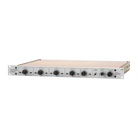
MODEL 4010
1
0
0
Central Electronics
9300-2594-00
Rev
G
6/00
RTSTM
Includes:
Model 4001
Control Station for 4 IFB, 1 SA
Model 4001M
Control Station for 4 IFB, 1 SA with Microphone
Model 4002
Control Station for 8 IFB, 2 SA
Model 4002M
Control Station for 8 IFB, 2 SA with Microphone
Model
4003
Control Station for 12 IFB, 3 SA
Model 4lW3M
Control Station for 12 IFB, 3 SA with Microphone
Model 4020
Portable User Statlon / Talent Electronics
Advertisement
Table of Contents

Related Manuals for RTS 4010

Summary of Contents for RTS 4010
- Page 1 TECHNICAL MANUAL MODEL 4010 Central Electronics Includes: Model 4001 Control Station for 4 IFB, 1 SA Model 4001M Control Station for 4 IFB, 1 SA with Microphone Model 4002 Control Station for 8 IFB, 2 SA Model 4002M Control Station for 8 IFB, 2 SA with Microphone...
- Page 2 TO THE FACTORY WITHOUT FIRST OBTAINING A RETURN AUTHORIZATION. The sole obligation of Telex during the warranty period is to provide, without charge, parts and labor necessary to Be prepared to provide the company name, address, remedy covered defects appearin in products returned phone number.
-
Page 3: Table Of Contents
........1.7.1 MODEL 4010 CENTRALELEClXONICS ....... 1.7.2 MODELS 40011400lM. - Page 4 ......6.5.7 BACK PANEL ASSEMBLY, MODEL 4010 -9020-213POO ....
-
Page 5: Introduction
SECITON 1: INTRODUCTION 13 CENTRAL ELECTRONICS MODEL4010 SPECIFiCATIONS The Central Electronics unit contains all the necessary l.l INTRODUCTION wntrol functions and electronics to provide the active link between the Control Station and the U s e r Station. It This IFB System is a one-way Interruptible FeedBacka accepts three program inputs, four microphone inputs wmmunications system (a program mterrupt system) and switch keying signal inputs from up... -
Page 6: Control Station Models
Inside the Model 4010, a single large circuit board is used snap-on cover housing. to mount all electronic wmponents. A rear-panel terminal strip provides connections for the program inputs, outputs, SA output, and relay contacts. - Page 7 W.1 MODEL 4010 CENTRAL ELECTRONICS Frequency Response 30 Hz to 16 kHz N o k * Interrupt channel Non-intempt channel Total Harmonic Distortion Nominal Input Level Miaophone @ line level -10 dBdinput Z=2k ohms Program 0 dBu/input Z=2k ohms Nominal Output Level...
- Page 8 Size And Weight 4001/4001M 4003/4003M Power Supply Power Requirements 14 VAC 200 mA 4001/4001M 14 VAC 450 mA 4002/4WZM 14 VAC 1.0 a m p 4003I4003M Specification Notes 1 kHz, measure at output terminal terminated into 600 ohms to 2 0 kHz, average Ref: 0 5 V +10 dBV, 20 responding meter.
-
Page 9: Wire And Cable
PHONES, TYPE USER STATIONS AND 1W" one Model 4010 Central Elwtronics, four Model 4020 OTHER SOURCES User Stations, one Model 4025 Splitter Assembly, and at least one Model 4001 Control Station. many as... -
Page 10: Control Station Operation
Central W h e n the switches inside the 4010 Electronics (see section 2.2.1, Setting Up Riority). Station 1 switched to the right both I& right charnels a t the user priority 1, station 2 has priority 2, etc. - Page 11 NEW VERSION OLD VERSION FROM POWER MODULE OR ALTERNATE SOURCE Figure To Series Power Connection 4000 Control Stations...
- Page 12 The system may be expanded for up to twelve. User Stations, three Central Electronics, three Splitter Ass- emblies and four Control Stations. See figures 23 and 2-4. Page...
- Page 13 CONTROL STATION STATION CONlROL STATION 1 x 4 SPUmR MODEL 4025 F i r e A ConGgumtion-2 System Page...
- Page 14 Figore A Contiguration-3 System...
- Page 16 FROM PROGRAM SOURCES Figure Pmgram Input And Output Connections Page 2-8...
- Page 17 OLD VERSION NEW VERSION Figwe 2-7 Balanced Mic Lavel Input...
- Page 18 NEW VERSION OLD VERSION Page 2-10...
-
Page 19: User Station Operation
APPROX EQUAL TO 0 dB SOURCE SUCH AS "USW TERMINAL OF USER STATION (ClRCUrf SIDE) NEW MRSION OLD VERSION Figurn 2-9 Une LeveI Input... - Page 20 Figwe 2-10 Control Station Cable Assembly Page 2-12...
- Page 21 P I -P4 DETERMINES PRIORITY W p m 2-11 Priority Connections To 4001 Control Station...
-
Page 22: Central Elf!Cironics
TO 1 s P I -P4 DETERMINES PRIORIN CENTRAL ELECTRONICS (OUTPUTS 1-4) P5 TALLY P1 -P4 DETERMINES PRIORITY CENTRAL ELECTRONICS P5 TAUY (OUTPUTS 5-8) Figure 2-I2 Priority ConnceUons 4002 Control Station Page 2-14... - Page 23 CENTRAL ELECTRONICS (OUTPUTS 1-4) PI-P4 DETERMINES 2 ' 4 0 PRIORITY CENTRAL ELECTRONICS TALLY (OUTPUTS 5-8) CENTRAL ELECTRONICS TALLY (OUTPUTS Figom 2-13 Prlodty C d o n s For Control Station 4 0 0 3 Page...
- Page 24 Figure 2-14 S p e a k Muting Zones 2-16 Page...
- Page 25 24VDC SUPPLY DPS CONNECTOR Figore 2-15 Return IFB Connestions Page 2-17...
- Page 26 IFB CENTRAL ELECTRONICS PCB 4010 CH 2 A = ONE OUTPUT: INTERUPT; ONE OUTPUT: NON-INTERUPT BOTH OUTPUTS: INTERUPT (CONTROLLED BY INTERUPT SWITCH AND LEVEL) Figure 2-16 Stereo-Mono IFB Selection Page 2-18...
- Page 27 4010. Wfi program playing into program input t h e monitor switch to PGM and ve* 1 , turn When using a single earplug, plug its cord into the program.
- Page 28 Balaneed/Unbalanced converters at each end. pair. figure 3 - 1 . ,,$$ 12VDC 2 m c MODEL 4010 MODEL 4020 5 MILES TWl S l E D PAlR TW STATION 1 /4w LOCAL POWER OPTION...
- Page 29 SECTION 4: THEORY OF OPERATION 4.3 CENTRAL ELECTRONICS FUNCTIONAL DESCRIPTION 4.1 INTRODUCTION POWERSUPPLY l % e Series 4000 system is designed to overcome power supply consists of T9, T10, and TI1 (schematic severid disadvantages of older conventional systems. Older diagram SD1914). each rated at 10 volts rms.
- Page 30 CENTRAL ELECTRONICS COMROL STATION MODELS 4001 MIC-PRE Line Diagram, Series 4000 IFB System...
- Page 31 INPUT SPEAKER MUTE PROGRAM AUDIO When the SA button on Control Station number 1 is The pmgram enters at the rear terminal strip through pressed, D67 (lower right) is pulled low, pulling pins 1 1 R160, a bridging pad, and resistors R241 R246, R158...
- Page 32 SWITCH 4001 BOARD The audio is received through J1. When any button is and intcMpted audio enters on pin two of the w pressed, the switch is closed and the audio passes through pawea panel connector (schemetic SD1905) to 13, pins 7 and 8. through D l which provides revem cunrat pmkdion.
- Page 33 REPLACEMENT 5 3 3 FUSE TEE FOLLOWING INSTRUCTIONS ARE FOR USE PERSONNEL ONLY. BY QUALIFIED TO AVOID Mode1 4010 Central E l m n i c s fuses. The one ELECTRIC SHOCK, DO NOT ACCESS THE rear panel is a...
- Page 34 LAMP Figure p Replacement Page...
- Page 35 Figure 5-2A Input Power Seleclion, Page...
- Page 36 CENTRAL UECT 4010 Figure 5-2B Input Power Selection, Page...
-
Page 37: Model 4010 Test Procedure
5.4 PERFORMANCE CHECK With program input, listen with belt pack on channel 1 . 5d.1 MODEL 4010 TEST PROCEDURE Listen for noise. Set controls for program in both ears, mono-stereo switch in stereo position. Press priority 4 l?qdpment Needed: IFBl, listen for interrupt in the left ear only. -
Page 38: Model 4001 Ifb
Splitter Assembly. Plug a tested 4001 Connect the left channel of the monitor headset jack (tip) into the Splitter Assembly also. Plug the splitter into the from the Model 4010 to the osdbscope, or plug in a set 4010 Central Electronics. of stereo headphones. - Page 39 Model 4010 to the or plug in a set of stereo headphones. Set the 4010 for program on Observe that the lights come on dimly. While watching the d o s c o p e (or listening in the headphones) press the four outputs and the SA output.
-
Page 40: Model 4020 User Station Test Procedure
Central Electronics powered. Look for the green Voltmeter on the front panel of the Model 4010 to be on. Check for Audio signal generator 29 volts dc on pins 1 and 2 of the connector going to RTS Systems power supply or Model 4010 Central the User Station. -
Page 41: Shipping List Model 4001
Immediately following the description of a part is the manufacture.r and the manufacturer's pan number. 6 . 2 HOW TO OBTAIN PARTS Pam may obtained directly f r o m Telex Communications, Inc.: Telex Communications, Inc. 12000 Portland Avenue South. Burnsville, 55337 U.S.A. - Page 42 6 3 . 1 E n d Assembly, Model 4001 9010-2003-00 (continued) Corn 50 Pin Male 3M 3564-1002 Ribbon Cabble Cond Spectra 843l352801050 I n s e r t Labels, Model 4001 Per 3382 Rinted M o d e l 4001, Mic Board, 6.32...
- Page 43 63.2 Rinted circuit Assembly, Model 4001, Mic Board, CC4000 9030-199900 RTS Part Number Switch Lens Holder Gray, 99-9208 Header, 14 Pin, DL Str, Berg 65611414 Header, 72 Pm Berg 65611472 PCB, 4001 SwBd (EAO) FAB Per Dwg 4375 Wnel, Model 4001 6 3 3 Front 9070-2006-00 pTS Part Number...
- Page 44 Finnl 6.4.1 Assembly; Model 4002 9010-U)ll&l Lens Cap, Plat C h EAO 99-921.7 Legend Plate, Flat 99-W.9 Cable Assy, Per Dwg 2483 Connector, 10 Pin 3M 3473-6010 Malc Cona 3M 3564-1002 Ribbon Cable 50 Cond Spectra 843l35U#)1050 Labels, Iasert Model 4001 Per 3382 Assembly.
-
Page 45: Front Panel, Model 4001M Gooseneck
6 . 4 3 Printed C h i t Assembly, Model 4002, Board 9030-437600 Switch pTS Part Number Coupling Piece EAO 99-910 1/Zw Res. 100 ohm Diode, MR502 Motorola Diode, lN4004 Amp, 400V Relay, Gordos 835Q MO Ohm, UV, Fom 1C JKL. - Page 46 65.1 FLnal Assembly, Modd 9010-M19-00 40Q7 Spacer, Hex 4-40 3/4 Smith 9402L 3/16 H. No Thd, Smith 9016 Spacer, 3/16 Soaffir. Hex 4-40 Smith 940U) &ble ~ T G C r a d l e panduit TMlS4 Elec Hex Jack Hdware RA-47-50-7 Screw, 9/16"...
-
Page 47: Front Panel. Model 4003
6.52 Printed Circuit Assembly, Model 4003, Pre Board, CC4MW) 9QU)-199P00 Part N m n k ~ M D t i 0 n Voltage Regulator, National LM317MP L C , Sietics NE5532N 8 Pin B d y DILSP-108 I.C. Socket, Header Molex 22-14-2044 Term Block 4 Pos Elcdrovett 251040453 Transformer, Audio Bonrns LMwCn Clrcnit Assembly, Model 4003,... - Page 48 6 5 5 Shipping Ust, Model 4010 9000-2365- RTS Part Number Model 4010 Central Ektronics Ln& T & B RAZZ17 Spade Washer, Nylon I 1 0 Smith 2674 Nnt, Hex 6-32 Serew, 10-32 112" Trnss Hd, Phil Cad Phil Scrcw, 6-32 318"...
-
Page 49: Printed Circuit
9100-233243 Cover Assembly, Mcdel4010 9020-2140-00 l303mmw Fibe& 14x16 .008Thk Cover, Top/Bottom Model 4010 Per FAB Dwg 1982 9100-1982-00 M o d e l 65.8 Printed Circuit Assembly, 4010, CC4010 9030-197400 RTS Part N u m k Washer, lock #4 Internal Tooth... - Page 50 Printed Cirmit Assembly, Model 4010, CC4010 9QU)-197440 RTS Part N& 1 1 % 820 ohm Res. 1.2lK ohm 1/4w 1% Res. 243 ohm 1/4w 1% Res. 27.4K 1/4w 1% Res. 4 . m ohm 1/4w 1% Res. WW 10 ohm 5w 5% Pot, 50K Audio "CP...
-
Page 51: Shipping List, Model 4020
6 . 5 3 Printed C i d t Assembly, Model 4010, CC4010 9000.197460 RTS Part Number I.C. Sodret, 14 Pin Burndy DIL14P-108 Socket, 16 Pin Burndy DIL16P-108 1 . C Term Strip 27 Po6 Mpum A104227Nl~R26 J& 114. SMK S - G ~ U P~OUO LP-20.6oO-B8... -
Page 52: Back Panel Assembly. Model
F i i Modd 4020 6.6.1 Assembly, 90101927M) W a s h e r , L d 375-32 Internal Tooth W a s h e r , Teflon Seastrom 561237-40 N u t , 375-32 Screw, f&l8 1/2" Flat Hd, Self Forming Knob, Gray Selm S150-250 Cap, Gray W/Dot S Z a m... - Page 53 6 . 6 3 Printed Assembly, Model 4020 9030-l!W-O1l (continued) Circuit Dwcriutio~ Part Number Q& 2.7 ohm 1/4w 5% Res. 470 ohm 1/4w P o t , SOKAudio 7OU4N040S503A "(2" Cap, 220pf/50v Cer Disc Radial Cap, 470pf/50v Cer Disc Radial Cap, Mono .lnf/50v .
- Page 55 APPENDIX SS2000 Microphone PreampURer Board Engineering Updates System moditied microphone preamplifier circuit board (SS2000) Models W1/400lu, used 4M)3/4003M Control Stations. 4002/4M)Ui2 If your control station was shipped prior to Jan 12,1987 and exhibits noise and hum, follow the fadory excessive guidelines and modify the SS2000 in your control station to correct the problem.
- Page 56 APPENDIX SS2000 Microphone PmmpUfia Board Engineering Updates Scrape away t k solder mask on the of R l 2 to make solder pads for a resistor. trace Install a wire with a tenon on the component side of the board where resistor W used sleeve to be.
- Page 57 APPENDIX SSUlOO Microphone Preamplifier Board Engineering Updates following resistors to circuit side of the board: R14 (mbhm) (1.X) Rl6 ( 9 . X ) / I - ,-SEE NOTE 9. RESISTOR ADDITIONS LOOKING FROM CIRCUIT SIDE OF PCB Securely fasten the modified back onto the control station.
- Page 58 APPENDIX SS2000 Microphone Preamplifier Board Engineering Updates Notes: Page A-4...
- Page 59 APPENDIX ADD MOMENTARY PUSHBUlTON SWITCH LAMP ADD #73 LAMP 12-14V AT 80rnA MODEL 4020 F@m E l Model 4020 ModiEcations Return Page B-1...
- Page 60 Notes:...
- Page 61 NOTES The following l i s t consists of manufacturers names and earphones, earsets headsets recommended for use with the Series 4000 IFB System's Model 4020 User Station Model Deschtion Earphone, ohms, ohms, ohms H D - 4 0 4 Earphone, Stethscope style...
- Page 62 Mini Headset, 2000 ohm single earphone; omni & a ! ! & Mini Headset, 600 ohms single earphone; omni microphone MHS-11 4 9 @ - 1 5 0 - 0 0 1 - 6 9 4 Commentators Headsct, 300 ohm single headphone; noise cancel 491-150-001-694 Commentators Headset, 300 ohm dual headphones;...
- Page 63 System. Control Station. Model 4001-4003. Sheet 2 of 2 7-16 SD2043 ......... Silkmeen Master. P.C.B.. Central Electronics. Model 4010 7-17 SS1973 ....... Assembly Diagram. Control Panel. 12 Station. System. Mode1 4003 7-18 AS4377 ..........Schematic Diagram, IFB Central Electronics. Model 4010 7-19 SD1914 (This section revised March 1991)
- Page 64 Notes: Page...
- Page 65 AS1999, Assembly Diagram, P . C . B . Mie Pre, Control Panel, IFB System, Model 4000 Page...
- Page 66 ASS123, 4000 Assembly Diagram, P.C.B., Mic Pre, Modifications To Update Rev C Artwork, Model BUS WIRE TEFLON ADD BUS WIRE JUMPER BETWEEN U l PINS b. ADD TO CIRCUIT S I D E : R I 4 ( 2 2 0 n ) PADS FOR Rl5.
- Page 67 Page 7-5...
- Page 68 V V V V V V V V V V V V V V V V V V V V V V V V V V V V V V V V V V V V V V V V ........
- Page 69 GOOSENECK M I C M O D E L 4001 M ONLY T O P VIEW 3 3 ( 0 3 . 5 3 ) A (149'36) M T G SCREW PLACES CONSOLE CUTOUT 7.938 (7.01.6) A L L D I M E N S I O N S : INCHES (mm) (215.4) u - -...
- Page 70 ID2464, Installation Dimensions, Models 4002,4002M, Control Panel "." m w m o m m . " GOOS€N€Cg MObEL 4 0 0 Z M ONLY VIEW M T 6 SCREW A PLACES CCUSOLE ALL DIMEM510NS I k K J C L I E S 1 0 .
- Page 71 GOOSENECK MODEL 4000 1.720 TOP VIEW (43.7) . I 0 7 (4.7) 1 - 1 1 1 1 1 S E W 4 PLACES -+I---- -------7 1.250 T Y P ( j S . 6 ) (31.15) - - - (mm) 1'7.00 (40~.6)
- Page 73 Page 7-1...
- Page 74 Page 7-12...
- Page 76 Page 7-14...
Need help?
Do you have a question about the 4010 and is the answer not in the manual?
Questions and answers