Table of Contents
Advertisement
Quick Links
Advertisement
Table of Contents

Related Manuals for Asus Pundit-PE3


Summary of Contents for Asus Pundit-PE3
- Page 1 Pundit Barebone System Model Pundit-PE3...
- Page 2 Product warranty or service will not be extended if: (1) the product is repaired, modified or altered, unless such repair, modification of alteration is authorized in writing by ASUS; or (2) the serial number of the product is defaced or missing.
-
Page 3: Table Of Contents
Table of contents Notices ....................vi Safety information ................vii About this guide ................viii System package contents ..............x Chapter 1: System Introduction Chapter 1: System Introduction Chapter 1: System Introduction Chapter 1: System Introduction Chapter 1: System Introduction Welcome! ................ - Page 4 Chapter 5: BIOS setup Chapter 5: BIOS setup Chapter 5: BIOS setup Managing and updating your BIOS ........5-2 5.1.1 ASUS CrashFree BIOS 2 utility ........ 5-2 5.1.2 ASUS Update utility ..........5-3 BIOS setup program ............. 5-6 5.2.1 BIOS menu screen ........... 5-7 5.2.2...
- Page 5 Table of contents Main menu ................5-9 5.3.1 System Time ............5-9 5.3.2 System Date ............5-9 5.3.3 Primary, Third, and Fourth IDE Master/Slave ..5-10 5.3.4 IDE Configuration ..........5-11 5.3.5 System Information ..........5-12 Advanced menu ..............5-13 5.4.1 USB Configuration ..........
-
Page 6: Notices
Notices Federal Communications Commission Statement Federal Communications Commission Statement Federal Communications Commission Statement Federal Communications Commission Statement Federal Communications Commission Statement This device complies with Part 15 of the FCC Rules. Operation is subject to the following two conditions: • This device may not cause harmful interference, and •... -
Page 7: Safety Information
Safety information Electrical safety Electrical safety Electrical safety Electrical safety Electrical safety • To prevent electrical shock hazard, disconnect the power cable from the electrical outlet before relocating the system. • When adding or removing devices to or from the system, ensure that the power cables for the devices are unplugged before the signal cables are connected. -
Page 8: About This Guide
Audience Audience This guide provides general information and installation instructions about the ASUS barebone system. This guide is intended for experienced users and integrators with hardware knowledge of personal computers. How this guide is organized How this guide is organized... - Page 9 Conventions used in this guide Conventions used in this guide Conventions used in this guide Conventions used in this guide Conventions used in this guide W A R N I N G : W A R N I N G : W A R N I N G : W A R N I N G : W A R N I N G : Information to prevent injury to yourself when...
-
Page 10: System Package Contents
A S U S P u n d i t - P E 3 b a r e b o n e s y s t e m w i t h • ASUS motherboard • 275 W PFC power supply unit 2 . - Page 11 Chapter 1 This chapter gives a general description of the barebone system. The chapter lists the system features including introduction on the front and rear panel, and internal components. A S U S P u n d i t - P E 3 A S U S P u n d i t - P E 3 A S U S P u n d i t - P E 3 A S U S P u n d i t - P E 3...
-
Page 12: Chapter 1: System Introduction
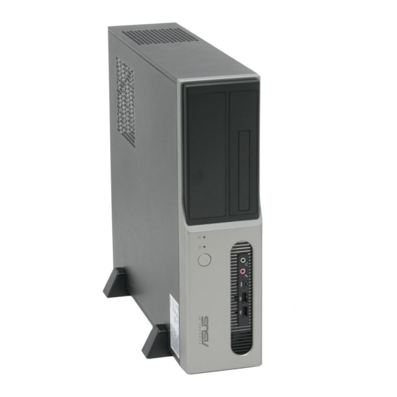
Thank you for choosing the ASUS Pundit-PE3! The ASUS Pundit-PE3 is an all-in-one barebone system with powerful and flexible features. The system comes in a stylish mini-tower casing, and powered by the ASUS motherboard that supports the Intel ® Pentium ®... - Page 13 5 . 5 . H e a d p h o n e p o r t H e a d p h o n e p o r t H e a d p h o n e p o r t .
-
Page 14: Rear Panel
Rear panel The system rear panel includes the power connector and several I/O ports that allow convenient connection of devices. 1 1 1 1 1 2 2 2 2 2 3 3 3 3 3 4 4 4 4 4 5 5 5 5 5 6 6 6 6 6 7 7 7 7 7... - Page 15 1 4 . 1 4 . U S B 2 . 0 p o r t s U S B 2 . 0 p o r t s ..These Universal Serial Bus 2.0 (USB 2.0) 1 4 .
-
Page 16: Internal Components
Hard disk drive bays Hard disk drive lock Power supply unit PCI Express x1 slot PCI slots ASUS motherboard 10. Metal bracket lock 11. LGA775 socket (under the CPU fan and heatsink assembly) 12. CPU fan and heatsink assembly 13. DIMM sockets... - Page 17 Chapter 2 This chapter provides step-by-step instructions on how to install components in the system. A S U S P u n d i t - P E 3 A S U S P u n d i t - P E 3 A S U S P u n d i t - P E 3 A S U S P u n d i t - P E 3 A S U S P u n d i t - P E 3...
-
Page 18: Chapter 2: Basic Installation
Preparation Before you proceed, make sure that you have all the components you plan to install in the system. Basic components to install Basic components to install Basic components to install Basic components to install Basic components to install Central processing unit (CPU) DDR Dual Inline Memory Module (DIMM) Expansion card(s) Hard disk drive... -
Page 19: Removing The Covers
Removing the covers 2.3.1 2.3.1 2.3.1 Removing the system cover Removing the system cover Removing the system cover 2.3.1 2.3.1 Removing the system cover Removing the system cover To remove the cover and metal chassis support: On the rear panel, locate the Remove the cover screws. -
Page 20: Removing The Front Panel Assembly
2.3.2 2.3.2 2.3.2 Removing the front panel assembly Removing the front panel assembly Removing the front panel assembly 2.3.2 2.3.2 Removing the front panel assembly Removing the front panel assembly To remove the front panel assembly: Place the system vertically. Pull the hooks outward to release the front panel Locate the front panel... -
Page 21: Installing The Cpu
Installing the CPU The ASUS motherboard comes with a surface mount LGA775 socket designed for the Intel ® Pentium ® 4 processor in the 775-land package. • Your boxed Intel ® Pentium ® 4 LGA775 processor package should come with installation instructions for the CPU, heatsink, and the retention mechanism. - Page 22 Lift the load lever in the direction of the arrow to a 135º angle. Lift the load plate with your thumb and forefinger to a 100º angle (A), then push the PnP cap from the load plate window to remove (B). L o a d p l a t e L o a d p l a t e L o a d p l a t e...
- Page 23 The CPU fits in only one correct orientation. DO NOT force the CPU into the socket to prevent bending the connectors on the socket and damaging the CPU! Close the load plate (A), then push the load lever (B) until it snaps into the retention tab.
- Page 24 Installing the CPU fan and heatsink assembly Installing the CPU fan and heatsink assembly Installing the CPU fan and heatsink assembly Installing the CPU fan and heatsink assembly Installing the CPU fan and heatsink assembly To install the CPU fan and heatsink assembly: Place the heatsink on top of the installed CPU, making sure that the four fasteners match the...
-
Page 25: Installing A Dimm
Installing a DIMM The system motherboard comes with four Double Data Rate (DDR) Dual Inline Memory Module (DIMM) sockets. The following figure illustrates the location of the sockets: ® 184-Pin DDR DIMM Sockets C h a n n e l C h a n n e l C h a n n e l S o c k e t s... - Page 26 Dual-channel memory configuration. C C C C C - supports four modules inserted into the blue and black slots as two pairs of Dual-channel memory configuration. Visit the ASUS website (www.asus.com) for the latest DDR Qualified Vendors List. 2 - 1 0...
-
Page 27: Removing A Dimm
2.5.2 2.5.2 2.5.2 Installing a DIMM Installing a DIMM Installing a DIMM 2.5.2 2.5.2 Installing a DIMM Installing a DIMM Make sure to unplug the power supply before adding or removing DIMMs or other system components. Failure to do so may cause severe damage to both the motherboard and the components. -
Page 28: Installing An Expansion Card
Installing an expansion card In the future, you may need to install expansion cards. The motherboard has two PCI and one PCI Express™ x1 slots. The following sub-sections describe the slots and the expansion cards that they support. The system supports l o w p r o f i l e l o w p r o f i l e l o w p r o f i l e l o w p r o f i l e PCI and PCI Express x1 cards. - Page 29 Remove the metal cover opposite the slot that you intend to use. P C I E x p r e s s x 1 s l o t P C I E x p r e s s x 1 s l o t P C I E x p r e s s x 1 s l o t P C I E x p r e s s x 1 s l o t P C I E x p r e s s x 1 s l o t...
- Page 30 Standard interrupt assignments Standard interrupt assignments Standard interrupt assignments Standard interrupt assignments Standard interrupt assignments I R Q I R Q I R Q I R Q I R Q S t a n d a r d F u n c t i o n S t a n d a r d F u n c t i o n S t a n d a r d F u n c t i o n S t a n d a r d F u n c t i o n...
-
Page 31: Installing An Optical Drive
Installing an optical drive The system comes with a 5.25-inch drive bay for an optical drive. If you plan to install an IDE hard disk drive, set the optical drive as a slave device before installing it to the system. Refer to the optical drive documentation for details on how to set the drive as slave device. - Page 32 Carefully push the optical drive all the way into the bay until the optical drive lock clicks. Connect a 4-pin power plug from the power supply unit to the power connector at the back of the drive. Uninstalling the optical drive Uninstalling the optical drive Uninstalling the optical drive Uninstalling the optical drive...
-
Page 33: Installing Hard Disk Drives (Hdds)
Installing hard disk drives (HDDs) The system comes with two 3.5-inch drive bays (labeled 1 and 2) for installation of two Serial ATA hard disk drives or one IDE HDD (if you have installed an optical drive). 2.8.1 2.8.1 Hard disk drive bays Hard disk drive bays 2.8.1 2.8.1... - Page 34 Connect one end of the supplied 7-pin SATA cable to the SATA connector at the back of the drive, then connect the other end to a SATA connector on the motherboard. See page 4-6 for the location of the SATA connectors.
-
Page 35: Ide Hard Disk Drive Installation
2.8.3 2.8.3 IDE hard disk drive installation IDE hard disk drive installation 2.8.3 2.8.3 2.8.3 IDE hard disk drive installation IDE hard disk drive installation IDE hard disk drive installation Set the IDE HDD as master device before connecting the IDE cable and power plug. -
Page 36: Replacing The Covers
Replacing the covers After you install all the necessary components to the system, replace the covers following the instructions in this section. 2.9.1 2.9.1 2.9.1 2.9.1 2.9.1 Replacing the front panel assembly Replacing the front panel assembly Replacing the front panel assembly Replacing the front panel assembly Replacing the front panel assembly If you installed an optical drive, you must remove the optical drive bay... -
Page 37: Replacing The System Cover
Swing the left edge of the front panel inward, then attach the front panel assembly hooks to the chassis until they snap in place. Do not use too much force when replacing the front panel assembly. 2.9.2 2.9.2 Replacing the system cover Replacing the system cover 2.9.2 2.9.2... -
Page 38: 2.10 Installing The Foot Stands
2.10 Installing the foot stands You need to install the foot stands to place the system vertically on your desktop. To install the foot stands: Lay the system on its side on a flat, stable, and elevated surface, then locate two screw holes on the left side of the system. -
Page 39: 2.11 Selecting The Voltage
2.11 Selecting the voltage The system’s power supply unit has a 115 V/230 V voltage selector switch located beside the power connector. Use this switch to select the appropriate system input voltage according to the voltage supply in your area. If the voltage supply in your area is 100-127 V, set the switch to 115 V. - Page 40 To the rear panel To the rear panel To the rear panel To the rear panel To the rear panel P P P P P o w e r o u t l e t o w e r o u t l e t o w e r o u t l e t o w e r o u t l e t o w e r o u t l e t...
- Page 41 Chapter 3 This chapter helps you power up the system and install drivers and utilities from the support CD. A S U S P u n d i t - P E 3 A S U S P u n d i t - P E 3 A S U S P u n d i t - P E 3 A S U S P u n d i t - P E 3 A S U S P u n d i t - P E 3...
-
Page 42: Chapter 3: Getting Started
The support CD that came with the system package contains the drivers, software applications, and utilities that you can install to avail all system features. The contents of the support CD are subject to change at any time without notice. Visit the ASUS website(www.asus.com) for updates. 3.2.1 3.2.1 3.2.1 3.2.1... -
Page 43: Drivers Menu
3.2.2 3.2.2 Drivers menu Drivers menu 3.2.2 3.2.2 3.2.2 Drivers menu Drivers menu Drivers menu The drivers menu shows the available device drivers if the system detects installed devices. Install the necessary drivers to activate the devices. QFE Update QFE Update QFE Update QFE Update QFE Update... -
Page 44: Utilities Menu
ASUS Update ASUS Update ASUS Update ASUS Update The ASUS Update utility allows you to update the motherboard BIOS in a Windows ® environment. This utility requires an Internet connection either through a network or an Internet Service Provider (ISP). See page 5-3 for details. -
Page 45: Asus Contact Information
C o n t a c t C o n t a c t C o n t a c t tab to display the ASUS contact information. You can also find this information on the inside front cover of this user guide. -
Page 46: Other Information
3.2.5 3.2.5 Other information Other information 3.2.5 3.2.5 3.2.5 Other information Other information Other information The icons on the top right corner of the screen give additional information on the motherboard and the contents of the support CD. Click an icon to display the specified information. - Page 47 Technical support form Technical support form Technical support form Technical support form Technical support form Displays the ASUS Technical Support Request Form that you have to fill out when requesting technical support. Filelist Filelist Filelist Filelist Filelist Displays the contents of the support CD and a brief description of each in text format.
- Page 48 3 - 8 3 - 8 3 - 8 3 - 8 3 - 8 C h a p t e r 3 : G e t t i n g s t a r t e d C h a p t e r 3 : G e t t i n g s t a r t e d C h a p t e r 3 : G e t t i n g s t a r t e d C h a p t e r 3 : G e t t i n g s t a r t e d C h a p t e r 3 : G e t t i n g s t a r t e d...
- Page 49 Chapter 4 This chapter gives information about the motherboard that comes with the system. This chapter includes the motherboard layout, jumper settings, and connector locations. A S U S P u n d i t - P E 3 A S U S P u n d i t - P E 3 A S U S P u n d i t - P E 3 A S U S P u n d i t - P E 3 A S U S P u n d i t - P E 3...
-
Page 50: Motherboard Overview
Motherboard overview Motherboard layout Motherboard layout Motherboard layout Motherboard layout Motherboard layout KBPWR1 PS/2KBMS CHA_FAN1 T: Mouse B: Keyboard CPU_FAN1 COM1 ATX12V1 LGA775 VGA1 Bottom: Top: USB1 1394 USB2 LAN_USB34 Intel 915GL Top:Line In Center:Line Out Below:Mic In ® PCI1 Intel LAN Chip Intel... -
Page 51: Jumpers
Jumpers 1 . 1 . C l e a r R T C R A M ( C L R T C 1 ) C l e a r R T C R A M ( C L R T C 1 ) C l e a r R T C R A M ( C L R T C 1 ) C l e a r R T C R A M ( C L R T C 1 ) C l e a r R T C R A M ( C L R T C 1 ) - Page 52 2 . 2 . U S B d e v i c e w a k e - u p ( 3 - p i n U S B P W 1 2 , U S B P W 3 4 , U S B d e v i c e w a k e - u p ( 3 - p i n U S B P W 1 2 , U S B P W 3 4 , U S B d e v i c e w a k e - u p ( 3 - p i n U S B P W 1 2 , U S B P W 3 4 , U S B d e v i c e w a k e - u p ( 3 - p i n U S B P W 1 2 , U S B P W 3 4 ,...
-
Page 53: Connectors
Connectors 4.3.1 4.3.1 4.3.1 Rear panel connectors Rear panel connectors Rear panel connectors 4.3.1 4.3.1 Rear panel connectors Rear panel connectors Refer to section “1.3 Rear panel” for a description of the rear panel I/O ports. 4.3.2 4.3.2 Internal connectors Internal connectors 4.3.2 4.3.2... - Page 54 2 . 2 . S e r i a l A T A c o n n e c t o r s ( 7 - p i n S A T A 1 , S A T A 2 ) S e r i a l A T A c o n n e c t o r s ( 7 - p i n S A T A 1 , S A T A 2 ) S e r i a l A T A c o n n e c t o r s ( 7 - p i n S A T A 1 , S A T A 2 ) S e r i a l A T A c o n n e c t o r s ( 7 - p i n S A T A 1 , S A T A 2 )
- Page 55 4 . 4 . U S B c o n n e c t o r s ( 1 0 - 1 p i n U S B 5 6 , U S B 7 8 ) U S B c o n n e c t o r s ( 1 0 - 1 p i n U S B 5 6 , U S B 7 8 ) U S B c o n n e c t o r s ( 1 0 - 1 p i n U S B 5 6 , U S B 7 8 ) U S B c o n n e c t o r s ( 1 0 - 1 p i n U S B 5 6 , U S B 7 8 ) U S B c o n n e c t o r s ( 1 0 - 1 p i n U S B 5 6 , U S B 7 8 )
- Page 56 6 . 6 . A T X p o w e r c o n n e c t o r s ( 2 4 - p i n E A T X P W R 1 , A T X p o w e r c o n n e c t o r s ( 2 4 - p i n E A T X P W R 1 , A T X p o w e r c o n n e c t o r s ( 2 4 - p i n E A T X P W R 1 , A T X p o w e r c o n n e c t o r s ( 2 4 - p i n E A T X P W R 1 , A T X p o w e r c o n n e c t o r s ( 2 4 - p i n E A T X P W R 1 ,...
- Page 57 8 . 8 . D i g i t a l a u d i o c o n n e c t o r ( 4 - 1 p i n S P D I F _ O U T 1 ) D i g i t a l a u d i o c o n n e c t o r ( 4 - 1 p i n S P D I F _ O U T 1 ) D i g i t a l a u d i o c o n n e c t o r ( 4 - 1 p i n S P D I F _ O U T 1 ) D i g i t a l a u d i o c o n n e c t o r ( 4 - 1 p i n S P D I F _ O U T 1 )
- Page 58 1 0 . 1 0 . 1 0 . 1 0 . 1 0 . S y s t e m p a n e l c o n n e c t o r ( 1 0 - 1 p i n F _ P A N E L 1 ) S y s t e m p a n e l c o n n e c t o r ( 1 0 - 1 p i n F _ P A N E L 1 ) S y s t e m p a n e l c o n n e c t o r ( 1 0 - 1 p i n F _ P A N E L 1 ) S y s t e m p a n e l c o n n e c t o r ( 1 0 - 1 p i n F _ P A N E L 1 )
- Page 59 Chapter 5 This chapter tells how to change system settings through the BIOS Setup menus and describes the BIOS parameters. A S U S P u n d i t - P E 3 A S U S P u n d i t - P E 3 A S U S P u n d i t - P E 3 A S U S P u n d i t - P E 3 A S U S P u n d i t - P E 3...
-
Page 60: Chapter 5: Bios Setup
ASUS CrashFree BIOS 2 utility ASUS CrashFree BIOS 2 utility The ASUS CrashFree BIOS 2 is an auto recovery tool that allows you to restore the BIOS file when it fails or gets corrupted during the updating process. You can update a corrupted BIOS file using the motherboard support CD that contains the original or updated BIOS file. -
Page 61: Asus Update Utility
ASUS Update utility 5.1.2 5.1.2 ASUS Update utility ASUS Update utility The ASUS Update is a utility that allows you to manage, save, and update the motherboard BIOS in Windows ® environment. The ASUS Update utility allows you to: • Save the current BIOS file •... - Page 62 A S U S U p d a t e A S U S U p d a t e. The ASUS Update main window appears. Select U p d a t e B I O S f r o m...
- Page 63 A S U S U p d a t e A S U S U p d a t e A S U S U p d a t e. The ASUS Update main window appears. A S U S U p d a t e...
-
Page 64: Bios Setup Program
The BIOS setup screens shown in this section are for reference purposes only, and may not exactly match what you see on your screen. • Visit the ASUS website (www.asus.com) to download the latest BIOS file for this motherboard. 5 - 6 5 - 6... -
Page 65: Bios Menu Screen
5.2.1 5.2.1 5.2.1 BIOS menu screen BIOS menu screen BIOS menu screen 5.2.1 5.2.1 BIOS menu screen BIOS menu screen M e n u i t e m s M e n u i t e m s M e n u i t e m s M e n u b a r M e n u b a r M e n u b a r... -
Page 66: Menu Items
5.2.4 5.2.4 Menu items Menu items 5.2.4 5.2.4 5.2.4 Menu items Menu items Menu items The highlighted item on the menu Use [ENTER], [TAB] bar displays the specific items for System Time [11:51:19] or [SHIFT-TAB] to System Date [Thu 06/10/2004] select a field. -
Page 67: Main Menu
Main menu When you enter the BIOS Setup program, the Main menu screen appears, giving you an overview of the basic system information. Refer to section “5.2.1 BIOS menu screen” for information on the menu screen items and how to navigate through them. System Time [11:51:19] Use [ENTER], [TAB] or... -
Page 68: Primary, Third, And Fourth Ide Master/Slave
5.3.3 5.3.3 5.3.3 Primary, Third, and Fourth IDE Master/Slave Primary, Third, and Fourth IDE Master/Slave Primary, Third, and Fourth IDE Master/Slave 5.3.3 5.3.3 Primary, Third, and Fourth IDE Master/Slave Primary, Third, and Fourth IDE Master/Slave While entering Setup, the BIOS automatically detects the presence of IDE devices. -
Page 69: Ide Configuration
PIO Mode [4] PIO Mode [4] PIO Mode [4] PIO Mode [4] PIO Mode [4] Selects the PIO mode. Configuration options: [Auto] [0] [1] [2] [3] [4] DMA Mode [Auto] DMA Mode [Auto] DMA Mode [Auto] DMA Mode [Auto] DMA Mode [Auto] Selects the DMA mode. -
Page 70: System Information
Enhanced Mode Support On [SATA mode] The default setting SATA allows you to use native OS on Serial ATA and Parallel ATA ports. We recommend that you do not change the default setting for better OS compatibility. In this setting, you may use legacy OS on the Parallel ATA ports o n l y i f o n l y i f o n l y i f... -
Page 71: Advanced Menu
Advanced menu The Advanced menu items allow you to change the settings for the CPU and other system devices. Take caution when changing the settings of the Advanced menu items. Incorrect field values can cause the system to malfunction. Configure the USB USB Configuration support. -
Page 72: Cpu Configuration
Legacy USB Support [Auto] Legacy USB Support [Auto] Legacy USB Support [Auto] Legacy USB Support [Auto] Legacy USB Support [Auto] Allows you to enable or disable support for USB devices on legacy operating systems (OS). Setting to [Auto] allows the system to detect the presence of USB devices at startup. - Page 73 Max CPUID Value Limit [Disabled] Max CPUID Value Limit [Disabled] Max CPUID Value Limit [Disabled] Max CPUID Value Limit [Disabled] Max CPUID Value Limit [Disabled] Enable this item to boot legacy operating systems that cannot support CPUs with extended CPUID functions. Configuration options: [Disabled] [Enabled] Enhanced C1 Control [Auto] Enhanced C1 Control [Auto]...
-
Page 74: Advanced Chipset Settings
5.4.3 5.4.3 5.4.3 Advanced Chipset Settings Advanced Chipset Settings Advanced Chipset Settings 5.4.3 5.4.3 Advanced Chipset Settings Advanced Chipset Settings The Advanced Chipset Settings menu allows you to change the advanced chipset settings. Select an item then press <Enter> to display the sub-menu. Enable or disable DRAM Advanced Chipset Settings timing. -
Page 75: Onboard Devices Configuration
Booting Graphic Adapter Priority [PCI/PCI Express] Booting Graphic Adapter Priority [PCI/PCI Express] Booting Graphic Adapter Priority [PCI/PCI Express] Booting Graphic Adapter Priority [PCI/PCI Express] Booting Graphic Adapter Priority [PCI/PCI Express] Allows selection of the graphics controller to use as primary boot device. Configuration options: [Internal VGA] [PCI /Int-VGA] Pre-allocated Graphics Memory [Enabled, 8MB] Pre-allocated Graphics Memory [Enabled, 8MB]... -
Page 76: Pci Pnp
Serial Port1 Address [3F8/IRQ4] Serial Port1 Address [3F8/IRQ4] Serial Port1 Address [3F8/IRQ4] Serial Port1 Address [3F8/IRQ4] Serial Port1 Address [3F8/IRQ4] Allows you to select the Serial Port1 base address. Configuration options: [Disabled] [3F8/IRQ4] [2F8/IRQ3] [3E8/IRQ4] [2E8/IRQ3] Parallel Port Address [378] Parallel Port Address [378] Parallel Port Address [378] Parallel Port Address [378]... - Page 77 Advanced PCI/PnP Settings Available: Specified IRQ is available to be WARNING: Setting wrong values in below sections used by PCI/PnP may cause system to malfunction. devices. Reserved: Specified IRQ Plug And Play O/S [No] is reserved for use by PCI Latency Timer [64] Legacy ISA devices.
-
Page 78: Power Menu
Power menu The Power menu items allow you to change the settings for the Advanced Power Management (APM) and Advanced Configuration and Power Interface (ACPI). Select an item then press <Enter> to display the configuration options. Select the ACPI state Suspend Mode [Auto] used for System... -
Page 79: Apm Configuration
5.5.5 5.5.5 5.5.5 APM Configuration APM Configuration APM Configuration 5.5.5 5.5.5 APM Configuration APM Configuration APM Configuration <Enter> to select whether or not to Restore on AC Power Loss [Power Off] restart the system Power On By RTC Alarm [Disabled] after AC power loss. - Page 80 Power On By External Modems [Disabled] Power On By External Modems [Disabled] Power On By External Modems [Disabled] Power On By External Modems [Disabled] Power On By External Modems [Disabled] This allows either settings of [Enabled] or [Disabled] for powering up the computer when the external modem receives a call while the computer is in Soft-off mode.
-
Page 81: Hardware Monitor
CPU Q-Fan Control [Disabled] CPU Q-Fan Control [Disabled] Allows you to enable or disable the ASUS Q-Fan feature that smartly adjusts the fan speeds for more efficient system operation. When this field C P U F a n R a t i o... - Page 82 CPU Target Temperature [xxxºC] CPU Target Temperature [xxxºC] CPU Target Temperature [xxxºC] CPU Target Temperature [xxxºC] CPU Target Temperature [xxxºC] Allows you to set the CPU temperature threshold when the CPU fan speed is increased to lower the CPU temperature. Configuration options: [Auto] [53ºC] [56ºC] [59ºC] [62ºC] [65ºC] [68ºC] [71ºC] [74ºC] [77ºC] [80ºC] [83ºC] Chassis Fan Speed [xxxxRPM] or [N/A]...
-
Page 83: Boot Menu
Boot menu The Boot menu items allow you to change the system boot options. Select an item then press <Enter> to display the sub-menu. Specifies the Boot Boot Settings Device Priority sequence Boot Device Priority Boot Settings Configuration Security 5.6.1 5.6.1 5.6.1 Boot Device Priority... -
Page 84: Boot Settings Configuration
This allows you to enable or disable the full screen logo display feature. Configuration options: [Disabled] [Enabled] Set this item to [Enabled] to use the ASUS MyLogo™ feature. Add On ROM Display Mode [Keep Current] Add On ROM Display Mode [Keep Current]... -
Page 85: Security
Hit ‘DEL’ Message Display [Enabled] Hit ‘DEL’ Message Display [Enabled] Hit ‘DEL’ Message Display [Enabled] Hit ‘DEL’ Message Display [Enabled] Hit ‘DEL’ Message Display [Enabled] When set to Enabled, the system displays the message “Press DEL to run Setup” during POST. Configuration options: [Disabled] [Enabled] Interrupt 19 Capture [Disabled] Interrupt 19 Capture [Disabled] Interrupt 19 Capture [Disabled]... - Page 86 If you forget your BIOS password, you clear it by erasing the CMOS Real Time Clock (RTC) RAM. See section “4.2 Jumpers” for information on how to erase the RTC RAM. After you have set a supervisor password, the other items appear to allow you to change other security settings.
- Page 87 Change User Password Change User Password Change User Password Change User Password Change User Password Select this item to set or change the user password. The User Password item on top of the screen shows the default N o t I n s t a l l e d N o t I n s t a l l e d N o t I n s t a l l e d.
-
Page 88: Exit Menu
Exit menu The Exit menu items allow you to load the optimal or failsafe default values for the BIOS items, and save or discard your changes to the BIOS items. Exit Options Exit & Save Changes Exit & Discard Changes Discard Changes Load Setup Defaults Pressing <Esc>... - Page 89 Load Setup Defaults Load Setup Defaults Load Setup Defaults Load Setup Defaults Load Setup Defaults This option allows you to load the default values for each of the parameters on the Setup menus. When you select this option or if you press <F5>, a confirmation window appears.
- Page 90 5 - 3 2 5 - 3 2 5 - 3 2 5 - 3 2 5 - 3 2 C h a p t e r 5 : B I O S s e t u p C h a p t e r 5 : B I O S s e t u p C h a p t e r 5 : B I O S s e t u p C h a p t e r 5 : B I O S s e t u p C h a p t e r 5 : B I O S s e t u p...
Need help?
Do you have a question about the Pundit-PE3 and is the answer not in the manual?
Questions and answers