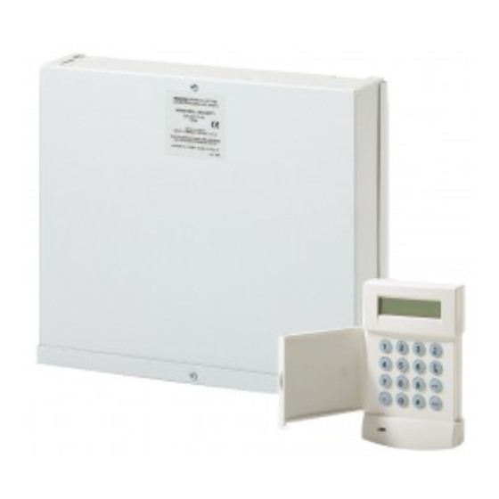
Honeywell Galaxy 2 Series, Galaxy 2-20 Manual
- Installation manual (118 pages) ,
- User manual (20 pages) ,
- Manual (2 pages)
Advertisement
Introduction
 NOTE: It is strongly recommended that any personnel installing a Galaxy 2 Series panel undertake appropriate training as supplied by Honeywell Security. This training is supplied free of charge and can be arranged by contacting Honeywell Security on:
Tel: +44 (0) 1355 354 000
Email: sales@ademco.co.uk
A full technical installation manual will be given to each installer at the training session. Additional manuals can be purchased from your distributor.
Setup
In order to get the system up and running, mount the panel and connect and address all peripherals as described below, before finally powering the system.
Peripheral Wiring
The following peripherals can be connected to the panel:
- Mk7 LCD Keypad/Keyprox x 4
- RIO/PSU x 1
- RF Portal x 2.
NOTE: The system must be wired in a daisy-chain configuration. Spur and star configurations must not be used. The recommended cable used to connect the RS485 (AB) line is twisted pair screened cable (Belden 8723 equivalent). However, for cable runs of less than 100m in normal environments, standard 4-core cable can be used.
| Panel | Peripheral |
| AUX+ | + |
| AUX– | – |
| A | A |
| B | B |
RS485 Peripheral Wiring
Peripheral Addressing
The address on most peripherals is set by either jumpers or a rotary switch. These must be set before the system is powered up. See the instructions with the peripheral for details.
The following table identifies the available peripheral addresses:
| Peripheral | Address |
| Mk7 Keypad/Keyprox | 0, 1, 2, 3 |
| RIO | 2 |
| PSU | 2 |
| RF Portal | 4, 5 |
Peripheral Addresses
Mains Supply Wiring
This product is not suitable for installation, maintenance or connection by the user. A competent, qualified engineer, with for example NSI approval, must carry out installation and maintenance.

A means of isolation from the mains supply must be provided within two metres of the control panel. Where live and neutral supplies can be identified, a fused spur with a 3A fuse must be fitted on the live circuit. Where live and neutral circuits cannot be readily identified, 3A fuses must be fitted to both circuits.
Connect the wires to the mains terminal block in the panel as follows:
- Blue (neutral) – connect to terminal N
- Green/Yellow (earth) – connect to terminal E
- Brown (live) – connect to terminal L
First Boot-up
After all the peripherals have been wired and addressed, apply power to the system. The keypads will configure and show the default banner display.

Default User Codes
Default User Code: 1234
Default Engineer Code: 112233
Menu Access Operation/Navigation
Only valid codes can access the Galaxy Series 2 menu options. Type the code then press ent to access the menu. Data entry is via the 0-9 function keys and the * and # on the keypad.
The A> and <B keys are cursor or scroll keys and are used to scroll through options in menus.
The ent key is used to enter a PIN code and to accept screen information.
The esc key is used to cancel or exit from the current operation.
NOTE: Users cannot view or access options for which they are not authorised.
How to get in and out of Engineer Mode
Entry to Engineer Mode is authorised by a user in menu option 48 = Level 3 Access. Following this, the engineer will have 5 minutes in which to enter his code.
When the engineer code is entered three things happen:
- All system tampers become isolated.
- The engineer is given access to the full menu.
- The banner message is changed to indicate Engineer Mode.
To bring the system back out of Engineer Mode and reinstate all the tampers, from the banner, the engineer enters his code, but then presses the esc key rather than the ent key. A 30-minute window is activated to allow the engineer back into engineer mode without re-authorisation by a user.
How to Set and Unset
To Full Set the system, the user types their code then presses the A key.
To Part or Night Set the system, the user types their code then presses the B key. The user now has a choice of pressing 1 to Part Set or 2 to Night Set.
To Unset the system, the user types their code then presses ent. Alternatively, presenting a valid tag at a prox reader or pressing the 'Off' key on a wireless keyfob can also unset the system.
How to Cancel an Alarm, Tamper or Fault
Alarms, tampers and fault conditions can be cancelled by entering a user code at a keypad. When the code is entered, the conditions activated will be displayed. The scroll keys (A> and <B) can be used to view all the events. Alarm conditions can also be cancelled by pressing the 'Off' button on a wireless keyfob or by presenting a valid tag at a proximity reader. However, a code will need to be entered at a keypad in order to see and restore the alarms.
How to Restore an Alarm
Alarms, tampers and fault conditions will be restored provided:
- The cause has cleared and
- A user with sufficient authority has viewed the condition on a keypad (any user if technistore).
If a user is unable to restore an alarm, then a manager or engineer will have to be called.
Zone Address Format
Galaxy zones are given addresses rather than zone numbers. This is because the zones are grouped into blocks of 8 called 'RIOs'. On board the panel there are 2 RIOs. The first RIO (0) has only 4 zones (addressed 1001 to 1004) and the second RIO (1) has 8 zones (addressed 1011 to 1018). As can be seen, the right hand digit is the individual zone number and the second digit is the RIO address, which can be 0 to 5, including all the expanders. Each zone can also be given a text descriptor. By default, it is blank.
All individual zone programming is done in menu 52.
Zone Wiring
The default zone configuration is 1k double-balanced as shown below:

Any unused hardwire zones should always have a 1k resistor wired across the zone terminals to terminate them.
The configuration for the zones and the resistance values used can be reprogrammed from menu option 51.46 = Parameters. Zone Resistance. The cable run on each zone should be no more than100 m.
Output Address Format
Galaxy outputs are addressed in the same way as the zones. However, there are only 4 outputs on each RIO. The on-board outputs are all on RIO 0 and have the addresses 1001 to 1004. RIO 1 on-board does not have programmable outputs.
All individual output programming is done in menu 53.
Output Wiring
The on-board outputs are all open-collector switched negative. The load that is to be controlled by an output should be connected between +12 V and the output terminal.
Note: Output 1002 is set up by default as a 16-ohm speaker driver. This means that the output gives an AC audio signal. This is not suitable for driving a normal sounder, relay, LED, etc. However, the mode can be changed in menu 51.15 if a normal output mode is needed.
Power Wiring
Auxiliary power can be drawn from the AUX+ terminals shown. The'common' terminals on the zones are 0 volts.

Communications
Built-in Comms
The Galaxy 2 Series has a built-in telephone dialler. The incoming telephone line should be wired to the 'Line In A B' terminals. The alarm panel should always be the first device on the phone line. Additional extensions should be connected to the serial terminals marked 'A B' next to the phone symbol. This will allow the panel to snatch the line when it needs to dial out.
All comms programming is done in menu 56.1.
External Stand-alone Dialler
An additional external dialler can be connected to the Galaxy 2 Series by way of the Trigger header. The connection comprises a cable that plugs on to the 12-way header in the centre of the main PCB. The other end of the cable connects to the terminal board which contains screw terminals for each core.. The pins of the 12-way header have the following functions:

The +12 V supply can supply a maximum of 100 mA but this reduces the total capacity of the panel's PSU by the same amount.
The function of the trigger outputs can be programmed in menu 53, under the output addresses 0001 to 0008.
Dual-path Signalling
When more than one comms device is fitted to the panel, one can be programmed as the main comms device and the other can be programmed as the backup/fail-safe that will only signal if the main device fails (line fault). This is controlled by menu 56.6. Each device can be given a hardware priority. Setting the priority to 0 means that device will never signal. Setting it to 1 means that it will always signal. Setting it to 2 means that it will only signal if the main device fails.
Menu Summary
All the functions of the panel are accessible via the menu.
The top level of the menu is summarised below:
| 10 = Setting | 20 = Display | 30 = Test |
| 11 = Omit Zones | 21 = Zone Status | 31 = Walk Test |
| 12 = Timed Set | 22 = View Log | 32 = Output Test |
| 13 = Part Set | 23 = System Version | |
| 14 = Night Set | 24 = Print | |
| 15 = Chime | ||
| 40 = Modify | 50 = Engineer 1 | 60 = Engineer 2 |
| 41 = Time/Date | 51 = Parameters | 61 = Diagnostics |
| 42 = Users | 52 = Zones | 62 = Full Test |
| 44 = Mobile Nos. | 53 = Outputs | 63 = Options |
| 47 = Remote Access | 56 = Comms | |
| 48 = Level 3 Access | 57 = System Print |
Each of these headings has its own sub options that can be accessed using the ent, esc and scroll keys.
Text programming
Certain options allow text to be entered. In these options, text is entered in the similar way to text messaging on mobile phones, by repeated presses of the number keys to select the appropriate letters. The keys have the following functions in text programming mode:
| Key | Output |
| 1 | & - 1 @ ' ( ). , # * + |
| 2 | A B C Ä Å Æ 2 a b c ä å æ |
| 3 | D E F 3 d e f |
| 4 | G H I 4 g h i |
| 5 | J K L 6 j k l |
| 6 | M N O Ö ø 6 m n o ö |
| 7 | P Q R 7 p q r s |
| 8 | T U V 8 t u v |
| 9 | W X Y 9 w x y z |
| 0 | [space] 0 |
| esc | Cancels the edit without saving changes |
| ent | Save string entry and exit |
| * | Deletes character to left of cursor |
| # | Deletes character at the cursor |
Code Tampers
When enabled (see menu option 51.14 = Parameters. Lockouts), and 10 wrong codes are entered in succession, the device is locked. The lockout lasts for 2 minutes. After a further 10 wrong code entries, a tamper is logged and a signal is given. The device is again locked out for 2 minutes.
Note: Wireless keyfobs and tags can still operate. Conversely, if a wrong tag is presented to a prox or an invalid wireless fob is activated for the same number of attempts, the prox and receiver devices are locked out, but the keypads still operate.
If a combination of devices are used to enter 10 wrong codes, then all those devices are locked out for 2 minutes.
Panel Specifications
Physical
Metal box - 1.2 mm steel
Width: 400 mm
Height: 255 mm
Depth: 115 mm
Weight: 4.2 kg
(with mains transformer and PCB installed)
Operating temperature -10oC to +40oC
Electrical
PSU Type A
Mains Input: 230 V ac (+10%, -15%), 50 Hz
Back-up Battery (not supplied):
Up to 12 Ah 12 V Sealed Lead-Acid (metal encl.).
Panel current: 100mA
PSU Max total load (from AUX, Bell, Trigger and STU outputs) 600mA
Max continuous ripple voltage 0.5V at max load
Individual 12 V outputs
Bell +12 V 500 mA max
Both Aux+ combined 500 mA max
Trigger Header +12 V 100 mA max
Switched Outputs
| Trigger Header Outputs | Can sink 30 mA each |
| Bell Trigger | Can sink 500 mA max |
| Strobe Trigger | Can sink 500 mA max |
| Trig output | Can sink 30 mA max |
| Speaker Output | 16 Ohms |
Fuses
| Mains | 200 mA, 20 mm Anti-surge (IEC 127) |
| Battery (F1) | 1 A, 20 mm Anti-surge |
| AUX (F2) | 500 mA, 20 mm Anti-surge |
| Bell (F3) | 500 mA, 20 mm Anti-surge |
Honeywell Security
2 Redwood Crescent
Peel Park Campus
East Kilbride
Glasgow
G74 5PA
UK
Documents / ResourcesDownload manual
Here you can download full pdf version of manual, it may contain additional safety instructions, warranty information, FCC rules, etc.
Advertisement


Need help?
Do you have a question about the Galaxy 2 Series and is the answer not in the manual?
Questions and answers