
Related Manuals for HP Engage Flex Pro G2


Summary of Contents for HP Engage Flex Pro G2
- Page 1 Maintenance and Service Guide HP Engage Flex Pro G2 Retail System SUMMARY This guide provides maintenance information about such topics as spare parts, removal and replacement of parts, security, and backing up.
-
Page 2: Legal Information
HP to be bound by the terms of the HP End Not all features are available in all Inc. under license. The terms HDMI, HDMI User License Agreement (EULA). - Page 3 Safety warning notice Reduce the possibility of heat-related injuries or of overheating the computer by following the practices described. WARNING! To reduce the possibility of heat-related injuries or of overheating the computer, do not place the computer directly on your lap or obstruct the computer air vents. Use the computer only on a hard, flat surface.
-
Page 4: Table Of Contents
Table of contents 1 Computer features.............................................. 1 Standard configuration features ....................................... 1 HP Engage Flex Pro G2..........................................1 Front panel components....................................... 1 Rear panel components ....................................... 2 Serial number location ........................................4 Changing from desktop to tower orientation................................5 Connecting external Wi-Fi antennas ....................................6 2 Illustrated parts catalog..........................................7... - Page 5 Battery................................................22 Optical drive..............................................23 Front bezel............................................... 23 Extra screw locations..........................................25 Rotating the drive cage ......................................... 26 Memory modules (DIMMs)........................................27 Expansion cards ............................................30 Expansion cards..........................................31 Riser assembly..........................................33 Solid-state drive............................................38 Front I/O assembly............................................40 Speaker................................................42 Optical drive cage ............................................. 43 Rotating the power supply........................................
- Page 6 Backing up information and creating recovery media............................ 91 Using Windows tools for backing up.................................. 91 Using the HP Cloud Recovery Download Tool to create recovery media (select products only)......91 Restoring and recovering your system..................................92 Creating a system restore ...................................... 92 Restoring and recovery methods ..................................
- Page 7 Japanese power cord requirements..................................105 Country-specific requirements .....................................105 12 Specifications ..............................................107 Index....................................................108...
-
Page 8: Computer Features
Standard configuration features Features vary depending on the model. For support assistance and to learn more about the hardware and software installed on your computer model, run the HP Support Assistant utility. NOTE: You can use this computer model in a tower orientation or a desktop orientation. -
Page 9: Rear Panel Components
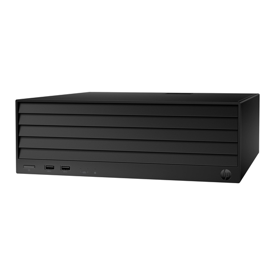
Table 1-1 Identifying the front panel components Front panel components Optical drive with eject button (optional) Network interface card activity lights (2) Power button Drive light USB 5 Gbps ports (2) NOTE: The light on the power button is normally white when the power is on. If the light blinks red, the computer displays a diagnostic code to indicate a problem. - Page 10 Identifying the rear panel components Rear panel components PCIe® x16 expansion slot (optional) USB 5 Gbps ports (3) PCIe x4 expansion slot (optional)* USB 5 Gbps port with HP Sleep and Charge Audio-out (headphone)/Audio-in (microphone) Flex Port 2 combo jack ®...
-
Page 11: Serial Number Location
You can disable the system board graphics by changing settings in the Computer Setup (F10) Utility. NOTE: To access the Computer Setup (F10) Utility, restart the computer and press the F10 key as soon as the HP logo screen is displayed, before the computer boots to the operating system. -
Page 12: Changing From Desktop To Tower Orientation
You can use the computer in a tower orientation with an optional tower stand that you can purchase from HP. NOTE: To stabilize the computer in a tower orientation, HP recommends the use of the optional tower stand. Remove or disengage any security devices that prohibit opening the computer. -
Page 13: Connecting External Wi-Fi Antennas
Reconnect the power cord and any external devices, and then turn on the computer. NOTE: Be sure that at least 10.2 centimeters (4 inches) of space on all sides of the computer remains clear and free of obstructions. Lock any security devices that you disengaged before you moved the computer. Connecting external Wi-Fi antennas Read this section to learn how to connect external Wi-Fi antennas to your computer. -
Page 14: Illustrated Parts Catalog
Use this information to determine the spare parts that are available for the computer. NOTE: HP continually improves and changes product parts. For complete and current information about supported parts for your computer, go to https://partsurfer.hp.com/partsurfer/, select your country or region, and then follow the on-screen instructions. - Page 15 Table 2-1 Computer major components and their descriptions (continued) Item Description Heat sink Processor Intel® Core® i5-13500TE processor Intel Core i5-13500E processor Intel Core i3-13100TE processor Intel Core i3-13100E processor System board NOTE: System boards are available for computers with a non-Windows® operating system, Windows IoT, and Windows.
-
Page 16: Miscellaneous Parts
Table 2-1 Computer major components and their descriptions (continued) Item Description Power serial adapter Dual-powered USB-to-serial port Cash drawer 24 V powered port (15) Hood sensor (16) Graphics card NVIDIA® T1000 NVIDIA RTX® A2000 (17) Fan duct (18) (19) Hard drive (3.5 inch) 4 TB, 7200 rpm, SATA-3 2 TB, 7200 rpm, SATA-3 1 TB, 7200 rpm, SATA-3... - Page 17 USB-C®-to-USB 3.0 Mini DisplayPort-to-DisplayPort DisplayPort-to-VGA USB-to-serial port USB-C-to-DisplayPort DisplayPort-to-HDMI 2.0 Mouse HP 125 antimicrobial wired mouse HP 125 wired mouse HP 128 laser wired mouse Keyboard USB keyboard HP 125 wired keyboard 2.5 in drive adapter 5.25 in-to-3.5 in hard drive adapter...
- Page 18 Table 2-2 Miscellaneous parts and their descriptions (continued) Description Optical drive adapter Optical drive bezel Computer chassis rear bracket Plastic WLAN antenna cover Low profile bracket for P600/P1000 graphics cards External wireless antenna Access panel plastic latch Power cord (C13, 1.83 m [6 ft]) Miscellaneous parts...
-
Page 19: Routine Care, Drive Guidelines, And Disassembly Preparation
Routine care, drive guidelines, and disassembly preparation This information provides general service information for the computer. Adherence to the procedures and precautions is essential for proper service. IMPORTANT: When the computer is plugged into an AC power source, DC voltage is always applied to the system board. -
Page 20: Preventing Electrostatic Damage To Equipment
Table 3-1 Static electricity occurrence based on activity and humidity (continued) Relative humidity Walking across carpet 7,500 V 15,000 V 35,000 V Walking across vinyl floor 3,000 V 5,000 V 12,000 V Motions of bench worker 400 V 800 V 6,000 V Removing DIPs (dual in-line packages) from plastic tube 400 V... -
Page 21: Grounding The Work Area
● Use field service tools, such as cutters, screwdrivers, and vacuums, that are conductive. Recommended materials and equipment HP recommends these materials and equipment to prevent static electricity. ● Antistatic tape ● Antistatic smocks, aprons, or sleeve protectors ●... -
Page 22: Operating Guidelines
● Opaque shielding bags ● Transparent metallized shielding bags ● Transparent shielding tubes Operating guidelines This information details how to prevent overheating and to help prolong the life of the computer. ● Keep the computer away from excessive moisture, direct sunlight, and extremes of heat and cold. ●... -
Page 23: Cleaning The Computer Case
● Disconnect the keyboard before cleaning it. ● Wear safety glasses equipped with side shields when cleaning the keyboard. Cleaning the computer case Follow all safety precautions before cleaning the computer case. To clean the computer case, follow these procedures: NOTE: You can also use these procedures to clean the tops of the keys, keyboard body, monitor body, or mouse body. -
Page 24: Cleaning The Monitor
The screws used in the computer are not interchangeable. They could have standard or metric threads and might be of different lengths. If you use an incorrect screw during the reassembly process, it can damage the unit. HP strongly recommends that you keep all screws that you remove during disassembly with the removed part and then return them to their proper locations. -
Page 25: Hard Drives
HP, their authorized partners, or their agents. SATA hard drives The Self Monitoring Analysis and Recording Technology (SMART) ATA drives for the HP Personal Computers have built-in drive failure prediction that warns the user or network administrator of an impending failure or crash of the hard drive. -
Page 26: Cable Management
Data transfer rate 6.0 Gbps Always use an HP-approved SATA 6.0 Gbps cable because it is fully backwards compatible with the SATA 1.5 Gbps drives. Current HP desktop products ship with SATA 6.0 Gbps hard drives. SATA data cables are susceptible to damage if overflexed. Never crease a SATA data cable and never bend it tighter than a 30 mm (1.18 in) radius. -
Page 27: Removal And Replacement Procedures
Not all features listed in this guide are available on all computers. NOTE: HP continually improves and changes product parts. For complete and current information about supported parts for your computer, go to https://partsurfer.hp.com/partsurfer/, select your country or region, and then follow the on-screen instructions. -
Page 28: Access Panel
■ Pull the dust filter straight off the outside of the front bezel. To install the dust filter, reverse the removal procedure. Access panel To remove the access panel, use this procedure and illustration. Before removing the access panel, prepare the computer for disassembly (see Preparation for disassembly on page 20). -
Page 29: Battery
Do not disassemble, crush, puncture, short external contacts, or dispose of in fire or water. ● Replace the battery only with the HP spare part that is designated for this product. IMPORTANT: Before replacing the battery, back up the computer CMOS settings. When the battery is removed or replaced, the CMOS settings are cleared. -
Page 30: Optical Drive
Slide the replacement battery into position, positive side up. The battery holder automatically secures the battery in the proper position. Optical drive To remove the optical drive, use this procedure and illustration. Before removing the optical drive, follow these steps: Prepare the computer for disassembly (see Preparation for disassembly on page 20). - Page 31 If the bezel is locked with a security screw, remove the screw from the top of the bezel. If a USB cap is installed, use a flat pry tool to release the cap from the bezel. Lift the three tabs (1) at the top of the bezel. Chapter 4 Removal and replacement procedures...
-
Page 32: Extra Screw Locations
Rotate the top of the bezel outward (2), and then pull the bezel (3) away from the computer. To remove the blank from the bezel, press the release tabs (1) on the inside of the bezel, and then rotate the blank (2) off the outside of the bezel. To install the front bezel, reverse the removal procedure. -
Page 33: Rotating The Drive Cage
Table 4-1 Extra screw locations Item Expansion slot Four silver 6/32 inch component screws One silver security screw Four black M3 drive screws Rotating the drive cage To rotate the drive cage upright, use this procedure and illustration. Before rotating the drive cage, follow these steps: Prepare the computer for disassembly (see Preparation for disassembly on page 20). -
Page 34: Memory Modules (Dimms)
■ Lift the green tab on the back of the drive cage to rotate it to the upright position. Memory modules (DIMMs) To remove the memory modules, use this information and procedures. The memory sockets on the system board are populated with at least one preinstalled memory module. To achieve the maximum memory support, you can populate the system board with up to 128 GB of memory configured in a high-performing dual-channel mode. - Page 35 Detected multi-bit errors cause the system to immediately reboot and halt with an F1 prompt error message. NOTE: Although HP does support non-ECC memory on this platform, non-ECC memory does not fully detect or correct single-bit or multi-bit errors, which can cause instability or corruption of data in the platform.
- Page 36 Static electricity can damage the electronic components of the computer or optional cards. Before beginning these procedures, be sure that you are discharged of static electricity by briefly touching a grounded metal object. For more information, see Electrostatic discharge information on page When handling a memory module, be careful not to touch any of the contacts.
-
Page 37: Expansion Cards
To install a memory module, open both latches (1) of the memory module socket, and insert the memory module into the socket (2). Press the module down into the socket so that the module is fully inserted and properly seated. Be sure that the latches (3) are in the closed position. NOTE: A memory module can be installed in only one way. -
Page 38: Expansion Cards
Table 4-3 Expansion slot locations Item Expansion slot PCI Express ×16 PCI Express ×4 PCI Express ×2 Riser card slot PCI Express ×2 IMPORTANT: The riser card expansion slot is specifically designed for the riser card for this product only. Do not attempt to plug any other type of card into this slot. Expansion cards To remove expansion cards, use these procedures and illustrations. - Page 39 Release the slot cover retention latch that secures the slot covers by lifting the green tab on the latch and rotating the latch to the open position. NOTE: Before removing an installed expansion card, disconnect any cables that may be attached to the expansion card.
-
Page 40: Riser Assembly
To remove a PCI card, pull the expansion card straight up and then away from the inside of the chassis to release it from the chassis frame. Be sure not to scrape the card against other components. CAUTION: After removing an expansion card, you must replace it with a new card or expansion slot cover for proper cooling of internal components during operation. - Page 41 Pull the expansion card out of the socket on the riser assembly. Different expansion cards might require a different bracket. The following illustration provides an example of removing a bracket from an expansion card by removing two screws (1) and pulling the bracket (2) off the card.
- Page 42 Release the slot cover retention latch that by lifting the green tab on the latch and rotating the latch to the open position. Lift the riser assembly out of the riser card slot. Riser assembly...
- Page 43 To disassemble the riser assembly, remove two screws that secure the bracket to the assembly, and then remove the bracket. To install an expansion card into the riser assembly: Pull back the tab on the expansion card retention latch to open the latch. Chapter 4 Removal and replacement procedures...
- Page 44 If installed, rotate an expansion slot cover to remove it from the riser assembly. Insert the end of the expansion card into an empty slot (1), and then press the other end against the chassis (2). NOTE: A powered serial port is shown. The expansion card can vary. If necessary, connect one end of the included cable into the card and the other end to the system board.
-
Page 45: Solid-State Drive
Solid-state drive To remove the solid-state drive, use these procedures and illustrations. For a list of available solid-states drives, see Computer major components on page Before removing the solid-state drive, follow these steps: Prepare the computer for disassembly (see Preparation for disassembly on page 20). - Page 46 Remove the Phillips screw (1) that secures the drive. Rotate the drive upward (2), and then pull the drive out of the socket (3). To remove the heat sink from the drive, pull all four heat sink arms (1) down slightly, and then pull the arms out of the slots (2) in the bracket.
-
Page 47: Front I/O Assembly
When installing a solid-state drive, be sure thermal pads are installed on the bottom of the heat sink (1) and the inside of the bracket (2). To install the solid-state drive, reverse the removal procedure. Front I/O assembly To remove the front I/O assembly, use these procedures and illustrations. Before removing the front I/O assembly, follow these steps: Prepare the computer for disassembly (see Preparation for disassembly on page... - Page 48 Remove one Torx screw (1) from the front grill, and then rotate the grill (2) from right to left and off the front of the computer. Disconnect the cable from the PB/LED connector (1) on system board. Disconnect the cable from the FRONT USB3 connector (2) on system board. From the front of the computer, remove the Torx screw (3) from the front I/O assembly.
-
Page 49: Speaker
Pull the assembly and cables (4) out of the front of the computer. To install the front I/O assembly, reverse the removal procedure. Speaker To remove the speaker, use this procedure and illustration. Before removing the speaker, follow these steps: Prepare the computer for disassembly (see Preparation for disassembly on page 20). -
Page 50: Optical Drive Cage
Remove the speaker from the connectors (3). To install the speaker, reverse the removal procedure. Optical drive cage To remove the optical drive cage, use this procedure and illustration. Before removing the optical drive cage, follow these steps: Prepare the computer for disassembly (see Preparation for disassembly on page 20). -
Page 51: Rotating The Power Supply
Slide the cage (2) toward the back of the computer, and then lift the cage (3) up and out of the computer. To replace the optical drive cage, reverse this procedure. Rotating the power supply To rotate the power supply upright, use this procedure and illustration. Before rotating the power supply, follow these steps: Prepare the computer for disassembly (see Preparation for disassembly on page... -
Page 52: Wlan Module
WLAN module To remove the WLAN module, use these procedures. Before removing the WLAN module, follow these steps: Prepare the computer for disassembly (see Preparation for disassembly on page 20). Remove the access panel (see Access panel on page 21). Rotate the power supply to the upright position (see Drive cage on page 44). -
Page 53: Hard Drive
If the WLAN antenna is not connected to the terminal on the WLAN module, a protective sleeve must be installed on the antenna connector, as shown in the following illustration. To install the WLAN module, reverse the removal procedure. NOTE: WLAN modules are designed with a notch to prevent incorrect insertion. -
Page 54: Fan Duct
Remove the secondary hard drive from the drive cage: Remove the optical drive cage from the rotating drive cage (see Optical drive cage on page 43). Disconnect the power and data cables (1) from the back of the drive. Press the release button (2), and then slide the drive (3) out of the drive cage. To install the hard drives, reverse the removal procedure. -
Page 55: Fan
Prepare the computer for disassembly (see Preparation for disassembly on page 20). Remove the access panel (see Access panel on page 21). Remove the fan duct: Remove the cable from the clip (1) on the duct. Lift the duct (2) straight up and out of the computer. To install the fan duct, reverse the removal procedure. -
Page 56: Heat Sink
Remove the fan (3) from the computer. To install the fan, reverse the removal procedure. Heat sink To remove the heat sink, use this procedure and illustration. Before removing the heat sink, follow these steps: Prepare the computer for disassembly (see Preparation for disassembly on page 20). -
Page 57: Processor
Thoroughly clean and replace the thermal grease from the surfaces on the system board and heat sink each time the heat sink is removed. Be sure that thermal grease is installed on the heat sink as shown in the following illustration. To install the heat sink, reverse the removal procedures. -
Page 58: Flex Card
To install the processor, reverse the removal procedures. NOTE: After installing a new processor onto the system board, update the system ROM to ensure that the computer using the latest version of the BIOS. Flex card To remove the flex card, use this procedure and illustration. Before removing the flex card, follow these steps: Prepare the computer for disassembly (see Preparation for disassembly on page... -
Page 59: Audio Board
Remove the flex card and cable (3) from the computer. To install the flex card, reverse the removal procedure. Audio board To remove the audio board, use this procedure and illustration. Before removing the audio board, follow these steps: Prepare the computer for disassembly (see Preparation for disassembly on page 20). -
Page 60: Serial Port
To install the audio board, reverse the removal procedure. Serial port To remove the serial port, use this procedure and illustration. Before removing the serial port, follow these steps: Prepare the computer for disassembly (see Preparation for disassembly on page 20). -
Page 61: Wlan Antennas And External Connectors
Remove the two Phillips screws (1) from the port. Lift the port (2) up to disconnect it from the connector on the system board. To install the rear expansion port, reverse this procedure. WLAN antennas and external connectors To remove the WLAN antennas and external connectors, use this procedure and illustration. Before removing the WLAN antennas and external connectors, follow these steps: Prepare the computer for disassembly (see Preparation for disassembly on page... -
Page 62: Power Supply
Remove the connector assembly and cables (5) from the computer. To install the WLAN antennas and external connectors, reverse the removal procedure. Power supply To remove the power supply, use these procedures. Before removing the power supply, follow these steps: Prepare the computer for disassembly (see Preparation for disassembly on page 20). -
Page 63: System Board
Rotate the power supply (1) up approximately 90°. Slide the power supply forward (2), and then lift it up and out of the computer (3). To install the power supply, reverse the removal procedures. System board To remove the system board, use this procedure and illustration. NOTE: All system board spare part kits include replacement thermal material. - Page 64 Rotate the drive cage to the upright position (see Rotating the drive cage on page 26). Rotate the power supply to the upright position (see Rotating the power supply on page 44). Remove the fan baffle (see Fan duct on page 47).
- Page 65 Remove the eight Torx screws (1) from the board. Slide the system board (2) toward the front of the computer enough to remove the connectors from the back of computer, and then lift the system board (3) out of the computer. To install the system board, reverse the removal procedure.
-
Page 66: Computer Setup (F10) Utility
Computer Setup (F10) Utility This information provides details of the Computer Setup Utility. ● Change settings from the defaults or restore the settings to default values. ● View the system configuration, including settings for processor, graphics, memory, audio, storage, communications, and input devices. ●... -
Page 67: Computer Setup Main
A choice of four headings appears in the Computer Setup Utilities menu: Main, Security, Advanced, and UEFI Drivers. NOTE: If you do not press at the appropriate time, you must restart the computer and again repeatedly press when the power button light turns white to access the utility. NOTE: Selecting UEFI Drivers restarts the computer into the third-party option ROM management application. - Page 68 Table 5-1 Computer Setup Main Option Description System Information Lists all information in following list if Advanced System Information is selected. Lists smaller subset if Basic System Information is selected. ● Product name ● Installed memory size ● Processor type ●...
- Page 69 Description System Diagnostics If the hard drive has the HP Advanced Diagnostics installed, the application launches. If HP Advanced Diagnostics is not installed, a basic version that is built into the BIOS provides the capability to perform the following functions: ●...
- Page 70 Check for Update on Next Reboot: Default is disabled. ● BIOS Source: Lets you select either HP.com or a custom URL. If Custom URL is selected, Edit Custom URL becomes active. HP recommends using a custom URL only for a managed IT environment.
-
Page 71: Computer Setup Security
Update BIOS Using Local Media Lets you access files on either USB storage or the hard drive. The HP BIOS Update and Recovery application included in BIOS Softpaqs at www.hp.com copies the BIOS file to the correct location on the hard drive or USB device. - Page 72 Table 5-2 Computer Setup Security Option Description Create BIOS Lets you set and enable a BIOS administrator password, which controls access to the following Administrator Password features: Setup Menu (F10) ● ● Third-Party Option ROM Management (F3) ● Update system ROM ●...
- Page 73 Manual recovery is intended only for situations when you want forensic analysis before HP Sure Start recovery. When this policy is set to manual, HP Sure Start will not correct any issues that are found until the local user enters the manual recovery key sequence. This can result in a computer that cannot boot until the manual recovery key sequence is entered.
- Page 74 HP firmware, while the operating system is running. – Log Event Only: HP Sure Start will log all critical security events in the HP Sure Start audio log within the HP Sure Start nonvolatile (flash) memory.
- Page 75 ● SPM Current State: Displays the current state. Also lets you change the state. ● Unprovision SPM: Deprovisions SPM, which causes HP Sure Run to revert to the inactive state and return HP Sure Recover to default settings. ● HP Sure Run Current State: Displays the current state. Also lets you change the state.
- Page 76 Table 5-2 Computer Setup Security (continued) Option Description Utilities Hard Drive Utilities ● Save/Restore GPT of System Hard Drive Enabling this feature saves the GUID Partition Table (GPT) of the system hard drive. If the GPT is subsequently changed, the user is prompted to choose whether to restore GPT. Default is disabled.
-
Page 77: Computer Setup Advanced
Computer Setup Advanced This table provides information about the Computer Setup Advanced menu. NOTE: Support for specific Computer Setup options can vary, depending on the hardware configuration. Table 5-3 Computer Setup Advanced (for advanced users) Option Heading Display Language Lets you select the language of the menus in F10 Setup and the keyboard layout. Scheduled Power-On This feature wakes the system when it is off at a specified date and time. - Page 78 Recover before Boot Failure Recovery If enabled and HP Sure Recover is launched because of a boot failure, the user is notified of the boot failure and asked to choose whether to start or cancel HP Sure Recover. This setting is displayed only if Recover after Boot Failure is selected.
- Page 79 Table 5-3 Computer Setup Advanced (for advanced users) (continued) Option Heading System Options Configure storage controller for Intel Optane™ (Intel products only) Enables the Intel Optane™ memory module. Configure storage controller for RAID Enables RAID. Default is enabled. Limit PCIe Speed (workstation models only) Lets you restrict the maximum speed of the PCI Express devices to previous generations.
- Page 80 Provides ACPI structure to enable HP common software application framework. The driver is provided in the latest HP support software that you can download from the web. NOTE: Device Manager shows an alert if this setting is enabled without the HP application driver installed. AMD DASH Lets you enable AMD Remote system management capability.
- Page 81 Table 5-3 Computer Setup Advanced (for advanced users) (continued) Option Heading Built-In Device Options Embedded LAN Controller (select products only) Select to show the device in the operating system. Default is enabled. Wake On LAN Lets you either disable the Wake On LAN feature or configure where the computer boots, including the network or hard drive.
- Page 82 Increase Idle Fan Speed (%) Increases the minimum fan speeds over the normal settings while still enabling normal control using the internal thermal sensors. Force enable HP Sure View Enables the HP Sure View privacy panel by changing the screen brightness. Computer Setup Advanced...
- Page 83 Table 5-3 Computer Setup Advanced (for advanced users) (continued) Option Heading Port Options USB ports (varies by model) Lets you enable specific USB ports. Default is enabled. USB Legacy Port Charging Lets you enable USB charging port capability when the computer is in hibernate or shutdown mode. Default is enabled.
- Page 84 Table 5-3 Computer Setup Advanced (for advanced users) (continued) Option Heading Power Management Runtime Power Management Options Allows certain operating systems to reduce processor voltage and frequency when the current software load does not require the full capabilities of the processor. Default is enabled. Extended Idle Power States Allows certain operating systems to decrease the processors power consumption when the processor is idle.
- Page 85 Table 5-3 Computer Setup Advanced (for advanced users) (continued) Option Heading Remote Management Active Management Technology (AMT) Options (Intel only) Allows you to discover, repair, and protect networked computing devices. Default is enabled. USB Key Provisioning Support Enables AMT provisioning using a USB storage device. Default is disabled. USB Redirection Support USB redirection allows USB devices plugged into a client computer to be transparently redirected to the guest operating system.
- Page 86 Sets the configuration for Remote HP PC Hardware Diagnostics, including the URLs used for download and upload and scheduled execution frequency. Execute Remote HP PC Hardware Diagnostics Select to immediately execute Remote HP PC Hardware Diagnostics based on the how settings are configured. Any unsaved BIOS settings will be lost. Computer Setup Advanced...
-
Page 87: Post Error Messages
POST error messages This section lists the error codes, error messages, and the various indicator light and audible sequences that you may encounter during Power-On Self-Test (POST) or computer restart, the probable source of the problem, and steps you can take to resolve the error condition. POST Message Disabled suppresses most system messages during POST, such as memory count and non-error text messages. - Page 88 Table 6-1 POST numeric codes and text messages (continued) Control panel message Description Recommended action 005-Real-Time Clock Power Loss Invalid time or date in configuration Reset the date and time under Control memory. RTC (real-time clock) battery Panel (Computer Setup can also be might need to be replaced.
- Page 89 Table 6-1 POST numeric codes and text messages (continued) Control panel message Description Recommended action 00D-Setup Error during MEBx Execution MEBx selection or exit resulted in a setup Reboot the computer. failure. Unplug the power cord, reseat the memory modules, and reboot the computer.
- Page 90 Drive Protection System test under using F2 Diagnostics when booting the computer. Apply hard drive firmware patch if applicable. (Available at http://www.hp.com/support.) Back up contents and replace hard drive. 302-Hard Disk 2: SMART Hard Drive Hard drive will soon fail. (Some hard...
- Page 91 Table 6-1 POST numeric codes and text messages (continued) Control panel message Description Recommended action 3F1–Hard Disk 1 Error Hard disk 1 error. Check and/or replace cables. Clear CMOS. Replace the hard disk drive. 3F2–Hard Disk 2 Error Hard disk 2 error. Check and/or replace cables.
- Page 92 Table 6-1 POST numeric codes and text messages (continued) Control panel message Description Recommended action 500–BIOS Recovery A system BIOS recovery has occurred. Not applicable. 70x-Wireless Mode Not Supported The system has detected a wireless Replace with a supported module. module installed in the system that is not supported and has been disabled.
-
Page 93: Interpreting Post Diagnostic Front Panel Lights And Audible Codes
Table 6-1 POST numeric codes and text messages (continued) Control panel message Description Recommended action 910–Filter Warning Airflow filter is dirty. Replace the airflow filter. 911–Graphics Module Fan Not Detected Graphics card fan is not connected or Reseat graphics card fan. might have malfunctioned. - Page 94 Table 6-2 Beep pattern error identification Number of long beeps/blinks Error category Not used BIOS Hardware Thermal System board Patterns of blink/beep codes are determined by using the following parameters: ● 1 second pause occurs after the last major blink. ●...
- Page 95 Table 6-3 Interpreting POST diagnostic front panel lights and audible codes (continued) Category Major/minor code Description Thermal A processor over temperature condition has been detected.* An ambient temperature over temperature condition has been detected. An MXM over temperature condition has been detected. System board The embedded controller cannot find valid firmware.
-
Page 96: Password Security And Resetting Cmos
Back up the BIOS settings or save them as custom defaults in case you need them later. You can back up in Computer Setup or with the BiosConfigUtility tool available from www.hp.com. See Computer Setup (F10) Utility on page 59 for information about backing up the BIOS settings. - Page 97 Turn on or restart the computer. To delete the Setup password, go to step 2. To delete the Power-on password, go to step 3. To delete the Setup password, as soon as the computer turns on: - Press while the “Press the ESC key for Startup Menu” message is displayed. - Press to enter Computer Setup.
-
Page 98: Backing Up, Restoring, And Recovering
Backing up, restoring, and recovering You can use Windows tools or HP software to back up your information, create a restore point, reset your computer, create recovery media, or restore your computer to its factory state. Performing these standard procedures can return your computer to a working state faster. -
Page 99: Restoring And Recovering Your System
HP recommends that you follow the Restoring and recovery methods on page 92 to restore your computer before you obtain and use the HP recovery discs. Using a recent backup can return your Chapter 8 Backing up, restoring, and recovering... -
Page 100: Changing The Computer Boot Order
HP recovery discs. After the system is restored, reinstalling all the operating system software released since your initial purchase can be a lengthy process. Changing the computer boot order If your computer does not restart using the HP Recovery media, you can change the computer boot order, which is the order of devices listed in BIOS for startup information. -
Page 101: Using Hp Pc Hardware Diagnostics
After HP PC Hardware Diagnostics Windows is installed, follow these steps to access it from HP Support Assistant: Complete one of the following tasks: ● Select the Search icon in the taskbar, type support in the search box, and then select the HP Support Assistant app. ● Select the question mark icon in the taskbar. -
Page 102: Accessing Hp Pc Hardware Diagnostics Windows From The Start Menu (Select Products Only)
To stop a diagnostic test, select Cancel. Accessing HP PC Hardware Diagnostics Windows from the Start menu (select products only) After HP PC Hardware Diagnostics Windows is installed, follow these steps to access it from the Start menu: Select the Start button, and then select All apps. -
Page 103: Installing Hp Pc Hardware Diagnostics Windows
HP UEFI support environment because only .exe files are provided. For more information, Downloading HP PC Hardware Diagnostics UEFI to a USB flash drive on page If your PC does not start in Windows, you can use HP PC Hardware Diagnostics UEFI to diagnose hardware issues. -
Page 104: Only)
Application. Proceed with the troubleshooting tests. Downloading HP PC Hardware Diagnostics UEFI to a USB flash drive Downloading HP PC Hardware Diagnostics UEFI to a USB flash drive can be useful in some situations. ● HP PC Hardware Diagnostics UEFI is not included in the preinstallation image. -
Page 105: Downloading The Latest Hp Pc Hardware Diagnostics Uefi Version
Find out more. Downloading Remote HP PC Hardware Diagnostics UEFI Remote HP PC Hardware Diagnostics UEFI is also available as a SoftPaq that you can download to a server. Downloading the latest Remote HP PC Hardware Diagnostics UEFI version You can download the latest Remote HP PC Hardware Diagnostics UEFI version to a USB flash drive. -
Page 106: Customizing Remote Hp Pc Hardware Diagnostics Uefi Settings
Set the location for downloading the diagnostic tools. This feature provides access to the tools from the HP website or from a server that has been preconfigured for use. Your computer does not require the traditional local storage, such as a hard drive or USB flash drive, to run remote diagnostics. -
Page 107: Statement Of Memory Volatility
No applications, features, or functionality were added to or installed on the system. Following system shutdown and removal of all power sources from an HP business computer system, personal data can remain on volatile system memory (DIMMs) for a finite period of time and also remains in nonvolatile memory. - Page 108 If an asset or ownership tag is set, select the Security menu and scroll down to the Utilities menu. Select System IDs, and then select Asset Tracking Number. Clear the tag, and then make the selection to return to the prior menu. If a DriveLock password is set, select the Security menu, and scroll down to Hard Drive Utilities under the Utilities menu.
-
Page 109: Nonvolatile Memory Usage
System boot ROM (BIOS) Non-volatile memory, 128 Mbit Download the latest BIOS (16 MB) socketed, removable for your model from the HP website and follow the instructions to flash the BIOS that are on the website RTC (CMOS) RAM Volatile memory, 256 bytes... - Page 110 HP has provided options in Computer Setup (BIOS) to allow you to run in legacy BIOS, if required by the operating system. Examples of this requirement would be if you upgrade or downgrade the OS.
-
Page 111: Using Hp Sure Start (Select Products Only)
Those select computer models ship with HP Sure Start configured and enabled. HP Sure Start is configured and already enabled so that most users can use the HP Sure Start default configuration. Advanced users can customize the default configuration. -
Page 112: Power Cord Set Requirements
Power cord set requirements The power supplies on some computers have external power switches. The voltage select switch feature on the computer permits it to operate from any line voltage of 100 V AC to 120 V AC or 220 V AC to 240 V AC. Power supplies on those computers that do not have external power switches are equipped with internal switches that sense the incoming voltage and automatically switch to the proper voltage. - Page 113 Table 11-1 Power cord country-specific requirements Country Accrediting Agency Country Accrediting Agency Australia (1) EANSW Italy (1) Austria (1) Japan (3) METI Belgium (1) CEBC Norway (1) NEMKO Canada (2) Sweden (1) SEMKO Denmark (1) DEMKO Switzerland (1) Finland (1) SETI United Kingdom (1) France (1)
-
Page 114: Specifications
Specifications This section provides specifications for your computer. Table 12-1 Specifications Metric U.S. Dimensions Height 337 mm 13.27 in Width 384 mm 15. 1 2 in Depth 100 mm 3.94 in Approximate weight 4.7 kg 10.4 lb Temperature range Operating 10°C to 40°C 50°F to 104°F Nonoperating... -
Page 115: Index
9 illustrated 7 hood sensor removal and replacement 20 removal and replacement 52 illustrated 9 HP PC Hardware Diagnostics UEFI downloading 97 failure ID code 96 electrostatic discharge (ESD) 12 backup, creating 91 HP Hotkey Support preventing damage 12, 13... - Page 116 USB flash drive 92 screws, correct size 12, 17 miscellaneous parts 9 recovery media 91 Security menu, Computer mouse creating using HP Cloud Setup 64 cleaning 12, 15, 17 Recovery Download Tool 91 serial number location 4 creating using Windows...
- Page 117 ventilation, proper 12, 15 Windows backup 91 recovery media 91 system restore point 91 Windows tools, using 91 WLAN antennas removal and replacement 54 WLAN module illustrated 8 removal and replacement 45 Index...
Need help?
Do you have a question about the Engage Flex Pro G2 and is the answer not in the manual?
Questions and answers