SilverStone Grandia Series, GD10, GD10B Manual
- Manual (36 pages) ,
- Manual (28 pages) ,
- Installation instructions manual (42 pages)
Advertisement
Product Overview
Introduction
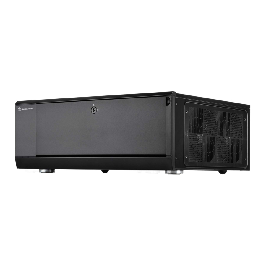
The Grandia GD10, along with GD09, is a culmination of SilverStone's decade-long experience in HTPC case design and manufacturing into a product that every PC enthusiast can enjoy. The incredible efficiency in which it utilizes all available space results in a case that is close in size externally to Micro-ATX based GD04 and GD05, yet capable of fitting most important full size standard components including wider ATX motherboards (SSI-CEB) such as ROG or other gaming-centric models. All drive cages have been designed similarly to those from the popular ML03 case to provide maximum flexibility in drive configuration without the need for additional adapters. For cooling, all positive pressure and smooth airflow designs were retained from previous Grandia models while improvements were made to filter access for even easier maintenance. With the addition of a lockable front door, the GD10 offers an attractively sized case that is capable and user-friendly for those interested in building a system with extra security and application that exceeds typical PC or HTPC environments.

Specification
| Material | Aluminum door with plastic front panel, 0.8mm steel body | |
| Model | SST-GD10B (black) | |
| Motherboard | SSI CEB, ATX, Micro ATX* | |
| Drive Bay | Exposed | 5.25" x 1 (compatible with 3.5" x 1 or 2.5" x 2) |
| Internal | 3.5" x 2 (one compatible with 2.5"), 2.5" x1 | |
| Cooling System | Right | 2 x 120mm intake fan, 900rpm, 18dBA |
| Rear | 2 x 80mm fan slot | |
| Top | Expansion card vent | |
| Left | 1 x 120mm fan, 900rpm, 18dBA, compatible with 80mm fan | |
| Expansion Slot | 7 + 1 | |
| Front I/O Port | USB 3.0 x 2, audio x 1, MIC x 1 | |
| Power Supply | Standard PS2 (ATX) 170mm maximum, 160mm recommended | |
| Expansion Card | Support cards up to 12.2 inches, width restriction 5.25" | |
| Limitation of CPU cooler | 138mm | |
| Net Weight | 4.8kg | |
| Dimension | 442mm (W) x 171mm (H) x 362mm (D), 27.4 liters | |
| Extra | Support Kensington lock, door lock | |
Disassemble Chart

| PICTURE | ITEM | PURPOSE |
 | SHOCK TANT - RING - YEL - GRAY | Anti-vibration rings |
 | KEY | KEY |
 | STANDOFF - 6 - 32 X 6.5H - 6 - 32 | Motherboard standoff |
 | SCREW - I - 6 - 32 X 5 - BK | Secure motherboard, PSU, 3.5" drives |
 | SCREW - P / W - M3 X 6 - BK | Secure 3.5" hard drive tray |
 | SCW - M3 X 4 - FLAT - BK | Secure 2.5" drives |
 | SCREW - PAN - 4 X 4.8H - 6 - 32 X 3.4 - NI | Secure 3.5" drives |
 | BUNCH - WIRE - TIES | Cable management |
Installation Guide
Before you begin, please make sure that you
- have all components collected
- check that all components do not have compatibility problems with each other or with the case
- if possible, assemble the components outside the case first to make sure they are working
- keep the motherboard manual ready for reference during installation
- prepare a Philips screwdriver.
- Unscrew screws from the rear of the chassis then remove the top cover

- Unscrew four screws from the optical drive bracket to remove it

- Unscrew two screws from the center brace to remove it

- Install power supply into the case. If you use a power supply with 120mm fan or bigger, we recommend installing it with the fan facing left (outwards). If the power supply itself is over 160mm or more in depth, you may need to remove the left case fan first before installation. For more information regarding power supply size limitations, please refer to the component guide

- Insert the I/O shield included with your motherboard into the rear I/O slot on the case

- If required, install additional motherboard standoffs onto the motherboard tray, then install the motherboard into the case and secure with SCREW C

- We recommend at this point to start thinking about routing the cables cleanly before connecting them to the motherboard, cables include fan cables, power supply 24pin cable, CPU ATX 4pin/EPS12V 8pin, front panel connectors, and front I/O connectors

- Install 2.5" drive onto the floor of the case and secure with screws. Make sure drive connectors are facing the rear of the case

- Use small bracket included in the accessories box to install 3.5" drive beneath the optical drive area

- Depending on your configuration, pre-connect any SATA cables to your motherboard before installing expansion cards

- Remove expansion slot covers as required, install expansion cards and secure with screws

- Install hard drive and optical drive to optical drive bracket as required. For more details on installation of this bracket, please refer to the guides in the later pages

- Remove 5.25" drive bay cover if needed

- Reinstall the center brace back into the case

- Reinstall the optical drive bracket back into the case

- Connect all data and power cables for installed drives. 90 degree angled connectors are recommended for better space saving

- Reinstall top cover back onto the case to complete installation


Connector definition
- Front panel connector installation no polarity, so they can be connected in any orientation
Power switch and reset switch installation guide:
Please refer to the motherboard manuals for the motherboard's "Front Panel Connector" or "System Panel Connector" pin definition Power switch and reset switch have no polarity, so they can be connected in any orientation.

- LED indicators installation guide
Please refer to the motherboard manuals for the motherboard's "Front Panel Connector " or "System Panel Connector" pin definition.; the white/black wires are negative while other colors are positive wires. The Power LED wires are separate pins for compatibility with different motherboard pin definition so please make sure they are connected in the right polarity by referring to your motherboard manual.

- Front I/O connector guide
Below are the front I/O connectors pin definition, please also check your motherboard manual to cross reference with motherboard's front I/O pin headers. SilverStone's I/O connectors are in block type to simplify installation.


Component size limitations
The GD10 was designed to be compatible with standard sized or some larger components, please refer to the following guidelines for component selection and future upgrade considerations.
CPU cooler height limitation


- The GD10 has 138mm height limitation for CPU cooler and clearance of 8mm beyond the motherboard. If no optical drive is installed, there is 170mm of room from the front panel to the motherboard edge.
- The clearance below the optical drive is 88mm.
The total distance from the front optical drive opening to the rear of the motherboard is 348mm, so if you know how long the optical drive is, then you can easily calculate the available area with the optical drive installed. - The illustration shows a SilverStone AR02 CPU cooler installed on a LGA115X platform with a 170mm long optical drive mounted. AR02's fan had to be installed on the rear of the heatsink to exhaust air toward the back of the case. If no optical drive was installed, then the fan can be installed facing the front drawing air into the heatsink. For both fan configurations, GD10's center brace barely clears AR02's heatsink.
Power supply limitations
- Depth limitation
The maximum PSU depth is 160mm if 120mm fan on the left side of the case and bottom 2.5" drives are installed. If no fan or 2.5" drives are required, then longer PSUs can be installed.

- Cable length recommendations
Below is a table of recommend cable length based off of common retail power supplies. Please make sure that the power supply you want to use has long enough cables to fit the below recommendations or you can also choose to purchase additional power cable extensions:

| Cable type and location | Minimum length |
| EPS 8pin/ATX4pin (from left side of PSU) | 500mm |
| ATX 24Pin (from left side of PSU) | 300mm |
| SATA 15Pin to optical drive | 450mm |
| SATA 15Pin to right 3.5" drive | 400mm |
| PCIe 8/6pin to first expansion slot | 400mm |
Graphics card/expansion card length limitation and relationship with center drive
- Length limitation
GD10 supports maximum of 12.2 inches long graphics cards - Drive connector
If graphics card is installed in the first expansion slot and there is a drive installed to the right, we recommend using 90 degree angled SATA connector with a height of no more than 16mm
![]()

| Graphic card length reference: | |
| AMD Radeon HD 7990 – 12" AMD Radeon HD 7970 NVIDIA GeForce GTX690 – 11" NVIDIA GeForce GTX780/TITAN - 10.5" NVIDIA GeForce GTX680/770 10" |
Motherboard width limitation

- Illustration: ASUS Rampage III Extreme is wider than standard ATX size of 9.6 inches
Although GD10 does not support true Extended ATX (SSI-EEB) motherboards, it does support ATX models up to 11 inches wide. Motherboard standoff holes are included to support SSI-CEB so high-end enthusiasts ATX boards such as ASUS Rampage III Extreme or EVGA X58 SLI Classified, which are up to 10.6 inches wide, can fit comfortably inside GD10. - Illustration: New generation of SSI-CEB server or workstation motherboards no longer require CPU cooler mounting holes on the motherboard tray.
Coolers can now be installed directly on the motherboard. As a result, we eliminated support for SSI-CEB CPU cooler mounting holes and instead increased the large gap on the motherboard tray to support CPU cooler back plates swapping with more LGA 115X motherboards. The GD10 chassis' support for new and future SSI-CEB motherboards should be unaffected by this change.
Recommended cooling device setup and selection
CPU cooler recommendation
- If you are installing a tower-style CPU cooler such as SilverStone's AR02, we recommend mounting its fan to blow into the heatsink and toward the rear of the case if there is no interference.
![]()
- If there is additional budget, choosing SilverStone's NT01-PRO is an alternative for quieter operation.
![]()
- When choosing a graphics card, we recommend models that have fan blowing exhaust air to the rear slot, this will ensure smooth and efficient airflow within the GD10 for maximum cooling performance.


Cable routing
There are lots of cable tie down loops around the motherboard area, in front of the PSU, on the drive cage, and in front of the expansion card area for use to securing cables as required.
Recommendation for fan installation
By default, GD10 includes 3 fans to nearly all cooling requirements. If you like to replace or add more fans, we recommend installing them as intake fans in the remaining fan slots except the rear.
Below are fan positions in relation to the components they provide cooling for:


| Right side fan, rear | CPU and components around CPU socket |
| Right side fan, front | Hard drive and CPU |
| Left side fan | Graphics cards |
| Rear fan | Assist in exhausting air |
SilverStone provides a selection of retail 120mm fans for upgrade or replacement
Upgrade and maintenance
Fan filter removal steps

Illustration: An example of a GPU cooler that is filled with dust and has lost most of its cooling performance GD10's positive air pressure design is an effective configuration that will reduce dust buildup inside the case. Small air particles or lint will accumulate over time on intake filters instead of on the components inside the case. To maintain excellent cooling performance for years to come, we recommend to clean all fan filters regularly every three months or half a year (depending on your environment). Below are steps to remove fan filters.

Illustration A: Right side filter can be removed

Illustration B: Left side filter for PSU can be removed
Extra expansion slot
GD10 has an extra expansion slot for use with device or short expansion card such as extra motherboard I/O, fan controller, SilverStone's ClearCMOS, or daughter board (e.g. ASUS Xonar HDAV1.3), Please refer to the following illustration for installation.

Multi-purpose drive cage design
Below illustrations shows corresponding mounting points for each drive slot:
There is no installation order if a 5.25" device is installed on top of the optical drive cage with 3.5" drive installed underneath. However, there are recommended orders when installing drive sizes smaller than original, please refer to the following table for more information:

| Bottom | ||
| Top | 3.5" | 2.5" |
| 5.25" | No order | Install bottom drive first |
| 3.5" | Install top drive first | Install bottom drive first |
| 2X2.5" | Install top drive first | Install top drive first |
Protect Your Device
Kensington Security Slot
A lock and cable can be purchased on the market for use with the Kensington security slot located on rear of GD10 to prevent removal of the entire computer or top cover.

Please check for compatibility before purchasing the lock and cable for use with GD10's Kensington security slot.
Q&A
I found that the GD10 is too large to fit in my home theater cabinet after installing the display output adapter. How can I solve this problem?
Please use the adapter cable as a replacement for the display output adaptor. The cable can be bent in any direction to ensure that the GD10 fits comfortably inside your home theater cabinet.

Additional info & contacts
For Noth America (usasupport@silverstonetek.com)
SilverStone Technology in North America may repair or replace defective product with refurbished product that is not new but has been functionally tested. Replacement product will be warranted for remainder of the warranty period of thirty days, whichever is longer. All product should be sent back ot the place of purchase if it is within 30 days of purchase, after 30 days, customers need to initiate RMA procedure with SilverStone Technology in USA by first downloading the "USA RMA form for end-users" form from the below link and follow its instructions.
http://silverstonetek.com/contactus.php
For Australia only (support@silverstonetek.com)
Our goods come with guarantees that cannot be excluded under the Australian Consumer Law.
You are entitled to a replacement or refund for a major failure and for compensation for any other reasonaly foreseeable loss or damage.
You are also entitled to have the goods repaired or replaced if the goods fail to be acceptable quality and the failure does not amount to a major failure.
SilverStone Technology Co., Ltd. 12F No. 168 Jinakang Rd., Zonghe Dist., New Taipei City 235 Taiwan R.O.C. +886-2-8228-1238
For Europe (support.eu@silverstonetek.de)
For China (support@silverstonetek.com.cn)
For all other regions (support@silverstonetek.com)
www.silverstonetek.com
support@silverstonetek.com
Documents / Resources
References
Download manual
Here you can download full pdf version of manual, it may contain additional safety instructions, warranty information, FCC rules, etc.
Advertisement


Need help?
Do you have a question about the Grandia Series and is the answer not in the manual?
Questions and answers