Table of Contents
Advertisement
Available languages
Available languages
Quick Links
LOVATO ELECTRIC S.P.A.
24020 GORLE (BERGAMO) ITALIA
VIA DON E. MAZZA, 12
TEL. 035 4282111
E-mail
info@LovatoElectric.com
Web
www.LovatoElectric.com
WARNING!
– This equipment is to be installed by qualified personnel, complying to current standards, to avoid
damages or safety hazards.
– The manufacturer cannot be held responsible for electrical safety in case of improper use of the equipment.
– Products illustrated herein are subject to alteration and changes without prior notice. Technical data and descriptions
in the documentation are accurate, to the best of our knowledge, but no liabilities for errors, omissions or
contingencies arising there from are accepted.
ATTENTION !
– Ces appareils doivent être installés par un personnel qualifié, conformément aux normes en vigueur en
matière d'installations, afin d'éviter de causer des dommages à des personnes ou choses.
– Le constructeur n'assume aucune responsabilité quant à la sécurité électrique en cas d'utilisation impropre du
dispositif.
– Les produits décrits dans ce document sont susceptibles d'évoluer ou de subir des modifications à n'importe quel
moment. Les descriptions et caractéristiques techniques du catalogue ne peuvent donc avoir aucune valeur
contractuelle.
ACHTUNG!
– Zur Vermeidung von Personen- und Sachschäden dürfen diese Geräte nur von qualifiziertem
Fachpersonal und unter Befolgung der einschlägigen Vorschriften installiert werden.
– Bei zweckwidrigem Gebrauch der Vorrichtung übernimmt der Hersteller keine Haftung für die elektrische Sicherheit.
– Die in dieser Broschüre beschriebenen Produkte können jederzeit weiterentwickelt und geändert werden. Die im
Katalog enthaltenen Beschreibungen und Daten sind daher unverbindlich und ohne Gewähr.
ADVERTENCIA
– Este dispositivo debe ser instalado por personal cualificado conforme a la normativa de instalación
vigente a fin de evitar daños personales o materiales.
– El fabricante no se responsabilizará de la seguridad eléctrica en caso de que el dispositivo no se utilice de forma
adecuada.
– Los productos descritos en este documento se pueden actualizar o modificar en cualquier momento.
Por consiguiente, las descripciones y los datos técnicos aquí contenidos no tienen valor contractual.
UPOZORNĚNÍ
– Tato zařízení smí instalovat kvalifikovaní pracovníci v souladu s platnými předpisy a normami pro předcházení
úrazů osob či poškození věcí.
– Výrobce nenese odpovědnost za elektrickou bezpečnost v případě nevhodného používání regulátoru.
– Výrobky popsané v tomto dokumentu mohou kdykoli projít úpravami či dalším vývojem. Popisy a údaje uvedené v katalogu
nemají proto žádnou smluvní hodnotu.
AVERTIZARE!
– Acest echipament va fi instalat de personal calificat, în conformitate cu standardele actuale, pentru a evita
deteriorări sau pericolele.
– Producătorul nu poate fi considerat responsabil pentru siguranţa electrică în caz de utilizare incorectă a echipamentului.
– Produsele ilustrate în prezentul sunt supuse modificărilor şi schimbărilor fără notificare anterioară. Datele tehnice şi descrierile
din documentaţie sunt precise, în măsura cunoştinţelor noastre, dar nu se acceptă nicio răspundere pentru erorile, omiterile
sau evenimentele neprevăzute care apar ca urmare a acestora.
I
MODULI DI SICUREZZA
GB SAFETY RELAYS
SRB...
ATTENZIONE!
– Questi apparecchi devono essere installati da personale qualificato, nel rispetto delle vigenti normative
impiantistiche, allo scopo di evitare danni a persone o cose.
– Il costruttore non si assume responsabilità in merito alla sicurezza elettrica in caso di utilizzo improprio del
dispositivo.
– I prodotti descritti in questo documento sono suscettibili in qualsiasi momento di evoluzioni o di modifiche.
Le descrizioni ed i dati a catalogo non possono pertanto avere alcun valore contrattuale.
UWAGA!
– W celu uniknięcia obrażeń osób lub uszkodzenia mienia tego typu urządzenia muszą być instalowane przez
wykwalifikowany personel, zgodnie z obowiązującymi przepisami.
– Producent nie przyjmuje na siebie odpowiedzialności za bezpieczeństwo elektryczne w przypadku niewłaściwego użytkowania
urządzenia.
– Produkty opisane w niniejszym dokumencie mogą być w każdej chwili udoskonalone lub zmodyfikowane. Opisy oraz dane
katalogowe nie mogą mieć w związku z tym żadnej wartości umownej.
ПРЕДУПРЕЖДЕНИЕ!
– Во избежание травм или материального ущерба монтаж должен существляться только
квалифицированным персоналом в соответствии с действующими нормативами.
– Производитель не несет ответственность за обеспечение электробезопасности в случае ненадлежащего
использования устройства.
– Изделия, описанные в настоящем документе, в любой момент могут подвергнуться изменениям или
усовершенствованиям. Поэтому каталожные данные и описания не могут рассматриваться как действительные с
точки зрения контрактов
DİKKAT!
– Bu aparatlar kişilere veya nesnelere zarar verme ihtimaline karşı yürürlükte olan sistem kurma normlarına göre
kalifiye personel tarafından monte edilmelidirler
– Üretici aparatın hatalı kullanımından kaynaklanan elektriksel güvenliğe ait sorumluluk kabul etmez.
– Bu dokümanda tarif edilen ürünler her an evrimlere veya değişimlere açıktır. Bu sebeple katalogdaki tarif ve değerler herhangi
bir bağlayıcı değeri haiz değildir.
UPOZORENJE!
– Ovaj uređaj mora instalirati, u skladu s važećim normama, obučena osoba kako bi se izbjegle štete ili sigurnosne
opasnosti.
– Proizvođač ne snosi odgovornost za električnu sigurnost u slučaju nepravilnog korištenja opreme.
– Ovdje prikazan uređaj predmet je stalnog usavršavanja i promjena bez prethodne najave. Tehnički podaci i opisi u ovim
uputama su točni, ali ne preuzimamo odgovornost za možebitne nenamjerne greške.
1
Advertisement
Chapters
Table of Contents

Related Manuals for LOVATO ELECTRIC SRB Series


Summary of Contents for LOVATO ELECTRIC SRB Series
- Page 1 MODULI DI SICUREZZA GB SAFETY RELAYS LOVATO ELECTRIC S.P.A. 24020 GORLE (BERGAMO) ITALIA VIA DON E. MAZZA, 12 TEL. 035 4282111 E-mail info@LovatoElectric.com SRB... www.LovatoElectric.com WARNING! ATTENZIONE! – This equipment is to be installed by qualified personnel, complying to current standards, to avoid –...
-
Page 2: Table Of Contents
Table of contents Introduction ..............................5 Safety ................................6 2.1 Functional safety ..........................................6 2.2 Lift safety standards..........................................6 Installation and environmental conditions .......................7 Wiring ................................8 4.1 Power supply............................................8 4.2 Wiring ..............................................8 Devices ................................9 5.1 Dimensions ............................................9 SRBES20 ...............................10 6.1 Terminal layout ............................................10 6.2 Operating modes ..........................................10 6.2.1 Manual start ..........................................10 6.2.2 Automatic start ..........................................11 6.2.3 Monitored manual start ........................................11... - Page 3 SRBEM41 ..............................26 8.1 Terminal layout ............................................26 8.2 Application ............................................26 8.2.1 Extension relay in single channel mode ..................................26 8.2.2 Extension relay in double channel mode ..................................27 8.3 Technical data ............................................28 8.3.1 Timing specification ........................................28 8.3.2 Safety specification ........................................28 8.3.3 Safety parameters ..........................................28 8.3.4 Power supply ..........................................28 8.3.5 Inputs ............................................28 8.3.6 Outputs.............................................29...
-
Page 4: Safety Messages
Service and warranty In the event of malfunction or requests for information please contact the LOVATO Electric branch or distributor in your country. Maintenance and repairs The device contains no parts that require maintenance. -
Page 5: Introduction
The SRB... safety relays are compliant with international standards, designed to provide the most comprehensive protection for equipment and personnel. They enable safety functions, accepting different types of inputs. All rights of this document are reserved by LOVATO Electric S.p.A. Validity of documentation This documentation is valid only for SRB...safety relays and until new documentation is published. -
Page 6: Safety
The device must be installed in accordance with the specific risk analysis of the application and all the applicable standards. LOVATO Electric is not responsible for these operations or for any risks in connection with them. Reference should be made to the manual and to the relative product and/or application standards to ensure correct use of any devices connected to the SRB... -
Page 7: Installation And Environmental Conditions
3. Installation and environmental conditions Warning: SRB... must be installed in a control cabinet with a protection grade of at least IP54, otherwise dampness or dust may lead to malfunction. Warning: Avoid installation during thunderstorms. Danger! If the safety relay is tampered, it can no longer ensure the safety of the operator and the warranty is void. Information: Use the notch on the rear of the unit to attach it to a DIN rail. -
Page 8: Wiring
4. Wiring 4.1 Power supply 24VDC ± 10%; 24VAC -15%/+10%, 50÷60 Hz, Class 2, overvoltage category III. 4.2 Wiring Warning: Max. terminal tightening torque: 0.5Nm (for all connections) Warning: Switch power supply OFF before wiring the device To prevent contact welding, a fuse should be connected on the output contacts. Sufficient fuse protection must be provided on all output contacts with capacitive and inductive loads. -
Page 9: Devices
5. Devices SRB... relays are compliant with international standards, designed to provide the most comprehensive protection for equipment and personnel. They enable safety functions, accepting different types of inputs. SRB... safety relays and expansion unit provide for safety instantaneous relay outputs. SRBES20 SRBES31 SRBEM41... -
Page 10: Srbes20
6. SRBES20 The SRBES20 relay monitors emergency stops, limit switches, magnetic switches according to 2006/42/CE Machinery Directives. The SRBES20 is also used for floor levelling and relevelling of lift cabin, according to the 2014/33/EU Lift Directive, in lift applications. 6.1 Terminal layout X1-X2: manual start / automatic start X1-X3: monitored manual start S11-S12: channel 1 NO input... -
Page 11: Automatic Start
6.2.2 Automatic start Connection between X1 and X2. The safety inputs S12 and S22 are operated: • contact closed between S11 and S12 • contact closed between S21 and S22 The safety outputs switch ON The opening of at least one safety input contact forces immediately the safety outputs to the open state A new operating cycle is possible only after releasing both input contacts and then operating them again... -
Page 12: Technical Data
Information: • The start/restart command must be installed outside the danger area in a position where the concerned danger and entire working area are clearly visible. • It must not be possible to reach the start/restart command from the inside of the danger area. Attention: Use in manual start mode is mandatory where the safety device controls an access protecting a danger zone. -
Page 13: Inputs
6.3.5 Inputs Number of safety channels Safety inputs (contact inputs) S11-S12 and S21-S22 Loop resistance Max. 1 kΩ Input current Typical 5 mA 6.3.6 Outputs Number of NO safety outputs Type Voltage free contact output, relays with forcibly guided contacts Max current rating - single output: @ 60°C (140°F) operating temperature: AC 1: 250V / 6A / 2000 VA - AC 15: 230V / 3A... -
Page 14: Environmental
6.3.8 Environmental IP40 on frontal part of the housing, IP20 on the terminals. The device has to be installed Protection grade in a cabinet with protection degree of IP54. Pollution degree -25 ÷ +60°C (-13 ÷ 140°F), UL: +40°C (104°F); Operating Temperature (tested @ temp 65°C (149 °F) as per lift norm) Storage Temperature... -
Page 15: E-Stop, Safety Limit Switch And Safety Interlocks (Single Channel Mode)
A cross circuit between the two channels will be recognized 6.5.2 E-stop, safety limit switch and safety interlocks (single channel mode) In case of a fault the safety outputs will switch OFF Pwr 24V (+/~) E-STOP Pwr 24V (-/~) Manual start Information: the release time in single channel mode is <... -
Page 16: Lift Levelling Application
6.5.4 Lift levelling application The SRBES20 is designed to be employed in lift plants for floor levelling and relevelling of the cabin, according to the requirements of EN/BS 81-20 and EN/BS 81-50 Standards, and according to the 2014/33/EU Lift Directive. Lift levelling with magnetic sensors The relay monitors the two re-levelling sensors and when the cabin is in the re-levelling zone, it enables the safety outputs. - Page 17 Lift levelling with photosensors The relay monitors the two re-levelling sensors and when the cabin is in the re-levelling zone, it enables the safety outputs. One safety output must be connected to bypass the circuit that monitors the cabin landing and cabin doors, when the lift cabin is inside the re-levelling zone; further to the landing and re-levelling of the cabin at the floor, the safety relay detects eventual faults and the lift controller will stop the lift.
-
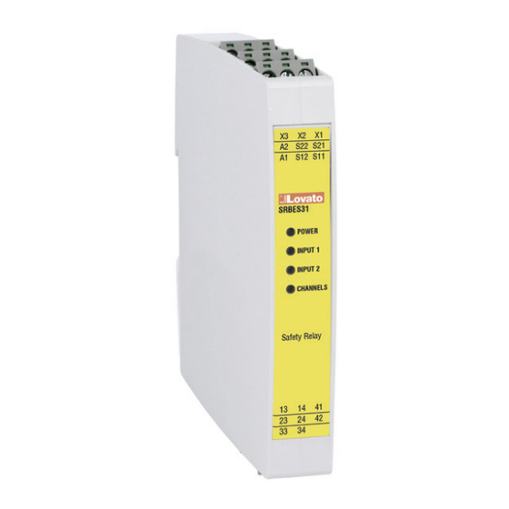
Page 18: Srbes31
7. SRBES31 The SRBES31 relay monitors emergency stops, limit switches, magnetic switches according to 2006/42/CE Machinery Directives. The SRBES31 is also used for floor levelling and relevelling of lift cabin, according to the 2014/33/EU Lift Directive, in lift applications. 7.1 Terminal layout X1-X2: manual start / automatic start X1-X3: monitored manual start S11-S12: channel 1 NO input... -
Page 19: Automatic Start
7.2.2 Automatic start Connection between X1 and X2. The safety inputs S12 and S22 are operated: • contact closed between S11 and S12 • contact closed between S21 and S22 The safety outputs switch ON, while the auxiliary output opens The opening of at least one safety input contact forces immediately the safety outputs to the open state A new operating cycle is possible only after releasing both input contacts... -
Page 20: Technical Data
Information: • The start/restart command must be installed outside the danger area in a position where the concerned danger and entire working area are clearly visible. • It must not be possible to reach the start/restart command from the inside of the danger area. Attention: Use in manual start mode is mandatory where the safety device controls an access protecting a danger zone. -
Page 21: Inputs
7.3.5 Inputs Number of safety channels Safety inputs (contact inputs) S11-S12 and S21-S22 Loop resistance Max. 1 kΩ Input current Typical 5 mA 7.3.6 Outputs Number of NO safety outputs Number of NC auxiliary outputs Type Voltage free contact output, relays with forcibly guided contacts Max current rating - single output: @ 60°C (140°F) operating temperature: AC 1: 250V / 6A / 2000 VA - AC 15: 230V / 3A... -
Page 22: Environmental
7.3.8 Environmental IP40 on frontal part of the housing, IP20 on the terminals. The device has to be installed Protection grade in a cabinet with protection degree of IP54. Pollution degree -25 ÷ +60°C (-13 ÷ 140°F), UL: +40°C (104°F); Operating Temperature (tested @ temp 65°C (149 °F) as per lift norm) Storage Temperature... -
Page 23: E-Stop, Safety Limit Switch And Safety Interlocks (Single Channel Mode)
A cross circuit between the two channels will be recognized 7.5.2 E-stop, safety limit switch and safety interlocks (single channel mode) In case of a fault the safety outputs will switch OFF Pwr 24V (+/~) E-STOP Pwr 24V (-/~) Manual start Information: The release time in single channel mode is <... -
Page 24: Lift Levelling Application
7.5.4 Lift levelling application The SRBES31 is designed to be employed in lift plants for floor levelling and relevelling of the cabin, according to the requirements of EN/BS 81-20 and EN/BS 81-50 Standards, and according to the 2014/33/EU Lift Directive. Lift levelling with magnetic sensors The relay monitors the two re-levelling sensors and when the cabin is in the re-levelling zone, it EN/BS ables the safety outputs. - Page 25 Lift levelling with photosensors The relay monitors the two re-levelling sensors and when the cabin is in the re-levelling zone, it enables the safety outputs. One safety output must be connected to bypass the circuit that monitors the cabin landing and cabin doors, when the lift cabin is inside the re-levelling zone; further to the landing and re-levelling of the cabin at the floor, the safety relay detects eventual faults and the lift controller will stop the lift.
-
Page 26: Srbem41
8. SRBEM41 The SRBEM41 is intended to expand the number of safety outputs of a master safety relay. It must be wired correctly to a master safety relay to reach the needed safety category. It can be used as an extension unit of safety relays with free-of-voltage relay output. 8.1 Terminal layout S11-S12: channel 1 NO input S21-S22: channel 2 NO input... -
Page 27: Extension Relay In Double Channel Mode
Input ch 1 Input ch 2 Safety output Feedback output <60ms <30ms 8.2.2 Extension relay in double channel mode • Connection of NO safety output 1 of the master relay between S11-S12 for input 1 • Connection of NO safety output 2 of the master relay between S21-S22 for input 2 When the safety relay outputs of the master safety relay are activated, the safety outputs of SRBEM41 switch ON, while the NC feedback output opens. -
Page 28: Technical Data
8.3 Technical data 8.3.1 Timing specification Activation time Ta < 60ms Release time Tr < 30ms Simultaneity Ts Infinite Min. start activation time 100ms Recovery time DC supply @ nom conditions < 500ms Recovery time AC supply @ nom conditions <... -
Page 29: Outputs
8.3.6 Outputs Number of NO safety outputs Number of NC feedback output Outputs type Voltage free contact output, relays with forcibly guided contacts Max current rating - single output: @ 60°C (140°F) operating temperature: AC 1: 250V / 6A / 2000 VA - AC 15: 230V / 3A EN/BS 60947-5-1 DC 1: 24V / 6A - DC 13: 24V / 2.5A / 0.1 Hz UL508... -
Page 30: Led Information
9. LED information 4 LEDs on the front panel indicate the status and any errors during operation: Status indicator Colour Status Meaning Power POWER Green SRB... is powered INPUT 1 INPUT 2 CHANNELS Safety Relay The safety devices connected to the inputs 1 and 2 are not IN1, IN2 Input 1 OFF active (e.g. -
Page 31: Total Current Σ Ith²
10. Total current Σ Ith² Quadratic total current [A²] = Output 1 current[A]² + Output 2 current[A]² + Output n current[A]² 11. Annex A: Glossary Term Definition The activation time is the time from the start/reset is activated and until the safety outputs Activation time (Ta) are energized (HIGH state). - Page 32 Indice Introduzione ..............................35 Sicurezza ..............................36 2.1 Sicurezza funzionale (direttiva macchine) ....................................36 2.2 Sicurezza ascensori (direttiva ascensori) .....................................36 Installazione e condizioni ambientali ........................37 Cablaggio ..............................38 4.1 Alimentazione ............................................38 4.2 Cablaggio ............................................38 Dispositivi ..............................39 5.1 Dimensioni ............................................39 SRBES20 ...............................40 6.1 Disposizione terminali .........................................40 6.2 Modalità...
- Page 33 SRBEM41 ..............................56 8.1 Disposizione terminali .........................................56 8.2 Applicazioni............................................56 8.2.1 Modulo di espansione in modalità singolo canale ...............................56 8.2.2 Modulo di espansione in modalità doppio canale ................................57 8.3 Caratteristiche tecniche ........................................58 8.3.1 Specifiche di temporizzazione ......................................58 8.3.2 Specifiche di sicurezza .........................................58 8.3.3 Parametri di sicurezza ........................................58 8.3.4 Alimentazione..........................................58 8.3.5 Ingressi ............................................58...
-
Page 34: Indicazioni Di Sicurezza
Esso deve essere conservato in buone condizioni e in luogo accessibile a tutti gli operatori. Servizio e garanzia In caso di malfunzionamento o richiesta di informazioni si prega di contattare il vostro referente presso LOVATO Electric oppure il distributore del vostro paese. -
Page 35: Introduzione
I moduli di sicurezza SRB...sono conformi agli standards internazionali, progettati per fornire protezione completa per attrezzature e personale. L’abilitazione delle funzioni di sicurezza può essere effettuata attraverso differenti tipologie di segnali di ingresso. Tutti i diritti di questo documento sono riservati a LOVATO Electric S.p.A. Validità del documento Questa documentazione è... -
Page 36: Sicurezza
Il dispositivo deve essere installato in conformità con l’analisi dei rischi specifici dell’applicazione e tutti gli standard applicabili. LOVATO Electric non è responsabile di tali operazioni o di eventuali rischi ad esse collegati. È necessario fare riferimento al manuale e ai relativi standard di prodotto e/o applicazione per garantire un uso corretto di tutti i dispositivi collegati al modulo SRB...all’interno dell’applicazione specifica. -
Page 37: Installazione E Condizioni Ambientali
3. Installazione e condizioni ambientali Avvertenza: Il modulo SRB...deve essere installato in un quadro elettrico con un grado di protezione pari ad almeno IP54, in caso contrario umidità o polvere potrebbero causare malfunzionamenti. Avvertenza: Evitare l’installazione durante i temporali. Pericolo! Se il modulo viene manomesso, non può... -
Page 38: Cablaggio
4. Cablaggio 4.1 Alimentazione 24VDC ± 10%; 24VAC -15%/+10%, 50÷60 Hz, Class 2, categoria di sovratensione III. 4.2 Cablaggio Attenzione: Max. coppia di serraggio dei morsetti: 0,5 Nm (per tutti i collegamenti) Avvertenza: Togliere alimentazione prima di collegare il dispositivo Per evitare la saldatura dei contatti, è... -
Page 39: Dispositivi
5. Dispositivi I moduli SRB...sono conformi agli standard internazionali, progettati per fornire la protezione più completa per attrezzature e personale. Consentono funzioni di sicurezza, accettando diversi tipi di ingressi. I moduli di sicurezza e di espansione SRB...forniscono uscite di sicurezza istantanee. SRBES20 SRBES31 SRBEM41... -
Page 40: Srbes20
6. SRBES20 ll modulo SRBES20 monitora gli arresti di emergenza, i finecorsa, gli interruttori magnetici secondo la direttiva macchine 2006/42 / CE. L’SRBES20 viene utilizzato anche per il livellamento e il rilivellamento della cabina al piano, secondo la Direttiva 2014/33/UE, per applicazioni nel settore ascensori 6.1 Disposizione terminali X1-X2: start manuale / automatico... -
Page 41: Start Automatico
6.2.2 Start Automatico Connessione tra X1 e X2. Gli ingressi S12 e S22 sono azionati: • contatto chiuso tra S11 e S12 • contatto chiuso tra S21 e S22 Le uscite sicure sono attive L’apertura di almeno un contatto di ingresso forza immediatamente l’apertura delle uscite sicure Una nuova attivazione delle uscite sicure è... -
Page 42: Caratteristiche Tecniche
Informazione: • Il comando di start/restart deve essere installato all’esterno dell’area pericolosa in una posizione in cui il potenziale pericolo e l’intera area di lavoro siano chiaramente visibili. • Non deve essere possibile raggiungere il comando di start/restart dall’interno dell’area pericolosa. Attenzione: L’uso in modalità... -
Page 43: Ingressi
6.3.5 Ingressi Numero di canali di ingresso Ingressi S11-S12 e S21-S22 Resistenza linea circuito ingressi Max. 1 kΩ Corrente di ingresso Tipica 5 mA 6.3.6 Uscite Numero delle uscite sicure NA Tipo Contatti liberi da tensione, relè con contatti a guida forzata Corrente max per ciascuna uscita: @ 60°C (140°F) temperatura di funzionamento: CA 1: 250V / 6A / 2000 VA - AC 15: 230V / 3A... -
Page 44: Parametri Ambientali
6.3.8 Parametri ambientali IP40 sul frontale della custodia, IP20 sui terminali. Il dispositivo deve essere installato in Grado di protezione un quadro elettrico con almeno un grado di protezione pari a IP54 Grado di inquinamento -25 ÷ +60°C (-13 ÷ 140°F), UL: +40°C (104°F); Temperatura di funzionamento (testato alla temperatura di 65°C (149°F) come da normative ascensori) Temperatura di immagazzinamento... -
Page 45: E-Stop, Finecorsa Di Sicurezza E Interblocchi Di Sicurezza (Modalità Singolo Canale)
Il cortocircuito tra i due canali di ingresso è rilevato. 6.5.2 E-stop, finecorsa di sicurezza e interblocchi di sicurezza (modalità singolo canale) In caso di guasto, le uscite sicure si disattivano ( il contatto si apre) Pwr 24V (+/~) E-STOP Pwr 24V (-/~) Manual start Informazione: il tempo di disattivazione in modalità... -
Page 46: Livellamento Ascensori
6.5.4 Livellamento ascensori L’ SRBES20 è progettato per essere utilizzato nel settore ascensoristico per il livellamento della cabina, in accordo con le normative EN/BS 81-20 e EN/BS 81-50, e secondo la direttiva ascensori 2014/33/EU. Livellamento ascensori con sensori magnetici Il modulo controlla i sensori di livellamento e quando la cabina si trova nella zona di livellamento, abilita le uscite sicure. - Page 47 Livellamento ascensori con sensori fotoelettrici Il modulo controlla i sensori di livellamento e quando la cabina si trova nella zona di livellamento, abilita le uscite sicure. Un’uscita sicura deve essere collegata al circuito di bypass che controlla il posizionamento al piano e l’apertura porte, quando la cabina è all’interno della zona di livellamento;...
-
Page 48: Srbes31
7. SRBES31 Il modulo SRBES231 monitora gli arresti di emergenza, i finecorsa, gli interruttori magnetici secondo la direttiva macchine 2006/42 / CE. L’SRBES231 viene utilizzato anche per il livellamento e il rilivellamento della cabina al piano, secondo la Direttiva 2014/33/UE, per applicazioni nel settore ascensori 7.1 Disposizione terminali X1-X2: start manuale/automatico... -
Page 49: Start Automatico
7.2.2 Start automatico Il pulsante di start è collegato tra X1 e X2. Gli ingressi S12 e S22 sono azionati: • contatto chiuso tra S11 e S12 • contatto chiuso tra S21 e S22 Le uscite sicure sono attive mentre quella ausiliaria si disattiva L’apertura di almeno un contatto di ingresso forza immediatamente l’apertura delle uscite sicure Una nuova attivazione delle uscite sicure è... -
Page 50: Caratteristiche Tecniche
Informazione: • Il comando di start/restart deve essere installato all’esterno dell’area pericolosa in una posizione in cui il potenziale pericolo e l’intera area di lavoro siano chiaramente visibili • Non deve essere possibile raggiungere il comando di start/restart dall’interno dell’area pericolosa Attenzione: L’uso in modalità... -
Page 51: Ingressi
7.3.5 Ingressi Numero di canali di ingresso Ingressi S11-S12 e S21-S22 Resistenza linea circuito ingressi Max. 1 kΩ Corrente di ingresso Tipica 5 mA 7.3.6 Uscite Numero di uscite sicure NA Numero di uscite ausiliarie NC Tipo Contatti liberi da tensione, relè con contatti a guida forzata Corrente max per ciascuna uscita: @ 60°C (140°F) temperatura di funzionamento: AC 1: 250V / 6A / 2000 VA - AC 15: 230V / 3A... -
Page 52: Parametri Ambientali
7.3.8 Parametri ambientali IP40 sul frontale della custodia, IP20 sui terminali. Il dispositivo deve essere installato in Grado di protezione un quadro elettrico con almeno un grado di protezione pari a IP54 Grado di inquinamento -25 ÷ +60°C (-13 ÷ 140°F), UL: +40°C (104°F); Temperatura di funzionamento (testato alla temperatura di 65°C (149°F) come da normative ascensori) Temperatura di immagazzinamento... -
Page 53: E-Stop, Finecorsa Di Sicurezza E Interblocchi Di Sicurezza (Modalità Singolo Canale)
Il corto circuito tra i due canali di ingresso è rilevato 7.5.2 E-stop, finecorsa di sicurezza e interblocchi di sicurezza (modalità singolo canale) In caso di guasto, le uscite sicure si disattivano (il contatto si apre) Pwr 24V (+/~) E-STOP Pwr 24V (-/~) Manual start Informazione:... -
Page 54: Livellamento Ascensori
7.5.4 Livellamento ascensori L’SRBES31 è progettato per essere utilizzato nel settore ascensoristico per il livellamento della cabina, in accordo con le normative EN/BS 81-20 e EN/BS 81-50, e secondo la direttiva ascensori 2014/33/EU. Livellamento ascensori con sensori magnetici Il modulo controlla i sensori di livellamento e quando la cabina si trova nella zona di livellamento, abilita le uscite sicure. - Page 55 Livellamento ascensori con sensori fotoelettrici Il modulo controlla i sensori di livellamento e quando la cabina si trova nella zona di livellamento, abilita le uscite sicure. Un’uscita sicura deve essere collegata al circuito di bypass che controlla il posizionamento al piano e l’apertura porte, quando la cabina è all’interno della zona di livellamento;...
-
Page 56: Srbem41
8. SRBEM41 Il modulo SRBEM41 ha lo scopo di espandere il numero di uscite sicure di un modulo di sicurezza master. Deve essere collegato correttamente ad un modulo di sicurezza principale per raggiungere la categoria di sicurezza necessaria. Può essere utilizzato come unità... -
Page 57: Modulo Di Espansione In Modalità Doppio Canale
Input ch 1 Input ch 2 Safety output Feedback output <60ms <30ms 8.2.2 Modulo di espansione in modalità doppio canale • Collegamento dell’uscita sicura 1 NA del modulo master tra S11-S12 per l’ingresso 1 (ch1) • Collegamento dell’uscita sicura 2 NA del modulo master tra S21-S22 per l’ingresso 2 (ch2) Quando le uscite sicure del modulo master sono attive, le uscite sicure NA dell’SRBEM41 si attivano, mentre l’uscita di retroazione NC si disattiva L’apertura di almeno un’uscita sicura del modulo master forza l’immediata apertura delle uscite sicure del modulo SRBEM41 e la chiusura... -
Page 58: Caratteristiche Tecniche
8.3 Caratteristiche tecniche 8.3.1 Specifiche di temporizzazione Tempo di attivazione Ta < 60ms Tempo di rilascio Tr < 30ms Simultaneità Ts Infinito Tempo minimo di attivazione 100ms Recovery time in condizioni nominali con < 500ms alimentazione DC Recovery time in condizioni nominali con <... -
Page 59: Uscite
8.3.6 Uscite Numero di uscite sicure NA Numero di uscite di retroazione NC Tipo Contatti liberi da tensione, relè con contatti a guida forzata Corrente max per ciascuna uscita: @ 60°C (140°F) temperatura di funzionamento: AC 1: 250V / 6A / 2000 VA - AC 15: 230V / 3A EN/BS60947-5-1 DC 1: 24V / 6A - DC 13: 24V / 2.5A / 0.1 Hz UL508... -
Page 60: Informazioni Del Led
9. Informazioni del LED 4 I LED sul pannello frontale indicano lo stato e gli eventuali errori durante il funzionamento: Indicatore di stato Colore Stato Significato Alimentazione POWER Verde Il modulo SRB...è alimentato INPUT 1 INPUT 2 CHANNELS Safety Relay I dispositivi di sicurezza collegati agli ingressi 1 e 2 non sono IN1, IN2 Ingresso 1 OFF... -
Page 61: Corrente Totale Σ Ith²
10. Corrente totale Σ Ith² Corrente totale quadratica [A²] = corrente di uscita 1 [A]² + corrente di uscita 2 [A]² + corrente di uscita n [A]² 11. Allegato A: Glossario Termini Definizioni Il tempo di attivazione è il tempo che intercorre dall’attivazione dell’avvio/reset fino Tempo di attivazione (Ta) all’attivazione delle uscite di sicurezza (stato ALTO).
Need help?
Do you have a question about the SRB Series and is the answer not in the manual?
Questions and answers