Honeywell R7284 Series, R7284U1004 Manual
- Operator's manual (30 pages) ,
- Technicianís quick reference manual (8 pages) ,
- Quick reference manual (5 pages)
Advertisement
TECHNICIAN'S QUICK REFERENCE GUIDE
The following service procedures will help you become familiar with the R7284 electronic oil primary controls. For control operation, please refer to the basic control functions described on the back. For further information, wiring instructions and troubleshooting, please refer to the R7284 Installation Instructions, form number 69-2467.
Pump Priming Cycle
To facilitate purging air from the oil lines and filters, the R7284 can be placed in a purge routine by pressing and releasing the up arrow button during the Trial For Ignition.
In the advanced interface "PUMP PRIME" is displayed on the display along with the time left on the Trial for Ignition (TFI). Pressing the up arrow button adds a minute to the TFI time for a maximum of 10 additional minutes (press the up arrow button 10 times). Pressing the down arrow button subtracts a minute from the TFI time.
There is no visual indication for the basic interface control and the purge timing is limited to five minutes.
Home Screens (Advanced Interface)
Pressing the "i" button longer than 2 seconds in states other than Standby Interrupts control operation.
Once the held key is released a 3 second count down begins to restart the cycle if the call for heat is still present.
- Holding all 3 buttons longer than 2 seconds in any state puts the display in the Installer Setup (ISU) mode.
- Pressing "i" in any state enters the Diagnostic screen if diagnostics are enabled outside of the Installer Setup mode.
- Pressing up or down in any screen enters Error History if diagnostics are enabled outside of the Installer Setup mode.
Below is a typical progression of screens through a normal cycle.

Pressing up or down during the Ignition Trial enters pump prime.
Each press of the up button adds a minute, each press of the down button subtracts a minute from the pump prime time.
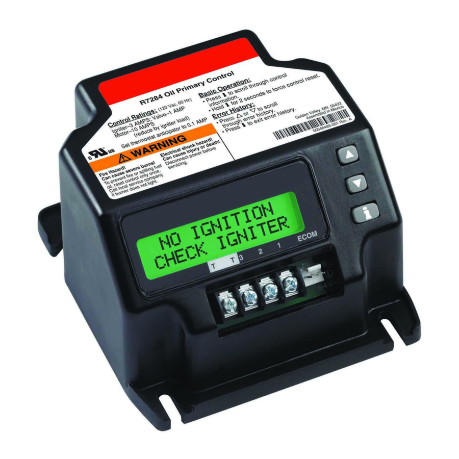
If at any point there is an event generating a lockout, one of the following screens will be displayed.

Control is in Soft Lockout. Control will recover when error clears or after specified time.

Control is in Hard Lockout. Hold "i" for at least 2 seconds to reset.

Hold the "i" button longer than 10 seconds to return to Standby.
Installer Setup (Advanced Interface)
Installer setup is entered by pushing all three buttons simultaneously for 2 seconds.

If QUIT is selected, an "i" button press displays the Re-baseline option.
If CONT is selected, an "i" button press goes to "Installer Setup".
 NOTE: Not all parameters are adjustable in all models. Parameters not available for adjustment will display "Locked" when an attempt is made to modify them.

Select between English, French, or Spanish by using the up or down buttons and the "i" button to select

Adjustment of the Valve On Delay in five second increments.

Ignition (lockout) Time adjustment.
NOTE: The Ignition Time is only available for adjustment during the first 100 cycles of operation. After 100 cycles the Ignition Time is locked in and can no longer be adjusted.

Adjustment of the Burner Off Delay. Burner Off Delay can be adjusted in 15 second increments from 0 to 8 minutes.

Configuration of the TT terminals vs. an "internal jumper." This option allows you to jumper the TT terminals electronically so no physical jumper is needed.

Controls sparking during On Delay period.

Controls sparking during Run mode (Interrupted vs. Intermittent ignition).

Number of resets allowed before Restricted Lockout

Appliance configuration (boiler, furnace, water heater) for EnviraCOM™.

Enable advanced diagnostics mode and error history. Selecting NO allows access to error history and diagnostics only by entering Installer Setup.

Exit installer setup

If "QUIT" is selected, the user is prompted with a screen asking if it is desired to rebaseline the control.
Error History Screens (Advanced Interface)
For all Error History screens, pressing "i" returns to the Normal Screen.

From the home screen, press the up button to display most recent error.

Press the up button again to proceed to the next most recent error or the down button to return to the previous error screen.

These three screens transition every 3 sec.
If no more errors are logged, the display shows "Error History End."
BASIC USER INTERFACE
The basic user interface consists of 3 buttons and an LED. Simple diagnostic information can be obtained through the interaction of the buttons and LED.
R7284 Status (Basic Interface)
Table 1. LED Codes.
| Description | LED Code |
| Standby | Pulse (1/4 sec. ON, 4 sec OFF) |
| Call for Heat | Heartbeat (1/2 sec bright, 1/2 sec dim) * |
| Flame proven | On solid |
| Recycle | 2 second ON, 2 second OFF flashing |
| Lockout | 1/2 second on, 1/2 second OFF flashing |
| Interrupt | OFF |
| "i" button | Flame Strength Indication |
| Up button | Most recent error |
| Down button | Next most recent error |
R7284 Flame Strength (Basic Interface)
During normal operation and when the R7284 is in the Running state, the LED will show CAD cell resistance. See Table 2.
Table 2. Flame Strength Indication.
| Flame Strength Indication | Number of 1/2 sec flashes |
| Cad Cell less than 400Ω | 1 |
| 400Ω < Cad Cell < 800Ω | 2 |
| 800Ω < Cad Cell < 1600Ω | 3 |
| 1600Ω < Cad Cell < 6100Ω | 4 |
| Cad Cell > 6100Ω | None |
Error History (Basic Interface)
The last two errors are available for display on the LED:
- Pressing the up arrow button displays the most recent error.
- Pressing the down arrow button displays the next most recent error.
Once the up or down arrow is pushed, the LED will display the most recent or next most recent alarm by blinking the error code. See Table 3.
R7284 Error Codes (Basic Interface)
Table 3. Error Codes.
| Error Codes | Number of 1/4 sec flashes |
| No ignition / Late ignition | 1 |
| Max flame losses / Cad Cell high while running | 2 |
| Flame out of sequence | 3 |
| Low Voltage / EnviraCOM™ error | 4 |
| Internal Error | 5 |
Documents / ResourcesDownload manual
Here you can download full pdf version of manual, it may contain additional safety instructions, warranty information, FCC rules, etc.
Advertisement


Need help?
Do you have a question about the R7284 Series and is the answer not in the manual?
Questions and answers