Advertisement
Protectorelay™ Primary Control
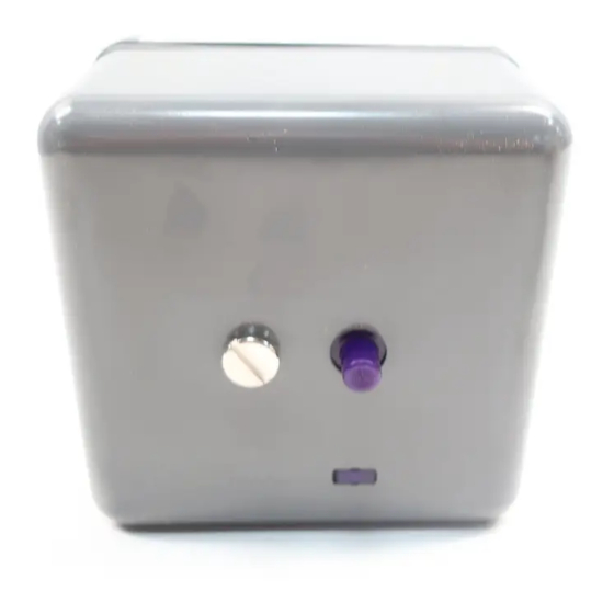
The RA890G Protectorelay™ control provides
solid state electronic safeguard protection for in-
dustrial and commercial gas, oil, or combination
gas-oil burners.
Designed for interrupted ignition with intermittent
pilot for gas burners, and for interrupted or inter-
mittent ignition on oil burners.
Used only with a C7027, C7035, or C7044 Mini-
peeper Ultraviolet Flame Detector.
Either a line voltage or low voltage controller can
be used.
Solid state circuitry eliminates warmup and in-
creases resistance to vibration.
Push-to-reset safety switch button is in dust-resis-
tant enclosure.
Safe start check prevents start if flame or flame
simulating failure is present.
S.Y. • Rev. 1-95 • ©Honeywell Inc. 1995
Automatic safety switch lockout if flame fails on
start or if flame is not re-established after a flame
failure.
When limit control opens, control de-energizes
ignition and fuel valves, but safety switch lockout
will not occur.
Test jack permits readings of flame signal.
Easy mounting and removal through use of captive
mounting screws. Durable thermosplastic mount-
ing base.
-40°F (-40°C) approved model available.
CONTENTS
Specifications ................................................. 2
Ordering Information ..................................... 2
Installation ..................................................... 3
Operation And Checkout ................................ 5
Service ............................................................ 8
Troubleshooting ............................................. 9
1
RA890G
60-2035-9
60-2035-9
Advertisement

Related Manuals for Honeywell RA890G


Summary of Contents for Honeywell RA890G
-
Page 1: Table Of Contents
Safe start check prevents start if flame or flame simulating failure is present. CONTENTS Specifications ..........2 Ordering Information ........2 Installation ............. 3 Operation And Checkout ........ 5 Service ............8 Troubleshooting ..........9 S.Y. • Rev. 1-95 • ©Honeywell Inc. 1995 60-2035—9 60-2035-9... -
Page 2: Specifications
Honeywell Inc., 1885 Douglas Drive North Minneapolis, Minnesota 55422-4386 In Canada—Honeywell Limited/Honeywell Limitée, 35 Dynamic Drive, Scarborough, Ontario M1V 4Z9. International Sales and Service Offices in all principal cities of the world. Manufacturing in Australia, Canada, Finland, France, Germany, Japan, Mexico, Netherlands, Spain, Taiwan, United Kingdom, U.S.A. -
Page 3: Installation
Amplifier or the C7076A Flame Detector with the Vibration R7476A Amplifier as the ultraviolet flame detec- Do not install the RA890G where it could be subject to tion system. excessive vibration. Vibration shortens the life of the elec- tronic components. - Page 4 500°F (260°C) for intermittent use. It was tested to 25,000 volts.) ALARM TERMINALS OPTIONAL. IF LINE VOLTAGE ALARM IS USED. RA890G MUST BE MOUNTED IN SUITABLE ENCLOSURE. ALARM b. For the flame detector F leadwire, use Honeywell TERMINALS ARE ENERGIZED THROUGH THE RA890 SAFETY SWITCH.
-
Page 5: Operation And Checkout
INSTALLATION • OPERATION AND CHECKOUT The use of manual reset limits is desirable with the Fig. 3—Oil-Fired system with interrupted RA890G to prevent the system from cycling off the high ignition. limit and to assure that the condition that causes the limita- tion is detected as soon as possible. - Page 6 2. The flame current is at least 1.5 microamperes for an of pilot before main fuel valve is opened). ultraviolet type detector such as used with the RA890G. Ignition Spark Response Test (all installations). If a satisfactory reading is not obtained, check the power Safe Shutdown Checks—Flame failure, power failure,...
- Page 7 1. Shut off pilot and main fuel manual valves. 2. Connect a W136 Microammeter and 196146 Test The pilot turndown test should be performed only Cable into the test jack on the RA890G. (See Flame Current by qualified personnel, and the instructions should check procedure section.) be followed carefully.
-
Page 8: Service
3. Use extreme care to avoid bending the contacts or that it is mounted securely (see controller instructions). changing the specifications or configuration in any 4. Never use oil on any part of the RA890G. way. 5. When cleaning the burner, clean the flame detector 4. -
Page 9: Troubleshooting
1. Use extreme care while troubleshooting the limit; if the load relay does not pull in, check again for power RA890G; line voltage is present on some termi- at terminal 6 with the controller calling for heat. If there is nals and contacts when power is on. - Page 10 RA890G TROUBLESHOOTING 1) Normal voltage—check valve and valve circuit. REPEATED LOCKOUTS OR CONTROL 2) Zero voltage—clean relay contacts. Replace the FAILURES RA890 if this does not correct problem. The most common causes of repeated failure of this 14. Observe ignition for cutoff when flame relay pulls in if control or flame detector or of repeated lockouts are: connected to terminal 4.
- Page 11 60-2035—9...
- Page 12 Home and Building Control Home and Building Control Helping You Control Your World Honeywell Inc. Honeywell Limited—Honeywell Limitée 1985 Douglas Drive North 740 Ellesmere Road Golden Valley, MN 55422 Scarborough, Ontario M1P 2V9 60-2035—9 Printed in U.S.A. www.honeywell.com/bbc...
Need help?
Do you have a question about the RA890G and is the answer not in the manual?
Questions and answers