
Related Manuals for ABB PCS100 AVC-40 1B


Summary of Contents for ABB PCS100 AVC-40 1B
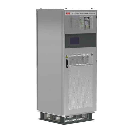
- Page 1 — 2UCD074000E013_B PCS100 AVC-40 1B Active Voltage Conditioner Low Power Range (P≤300 kVA) User Manual © Copyright 2020 ABB, All rights reserved.
-
Page 2: About This Document
We are an established world force in the design and manufacturing of power electronics and power protection equipment. As part of ABB, a world leader in electrical technology, we offer customers application expertise, service, and support worldwide. We are committed to teamwork, high quality manufacturing, advanced technology and unrivalled service and support. -
Page 3: Document Information
ABB Ltd. The hardware and software described in this manual are provided under a license and may be used, copied, or disclosed only in accordance with the terms of such license. -
Page 4: Safety
PCS100 AVC-40 1B User Manual — SAFETY Safety Instructions Attenzione: Tensione pericolosa! Fare riferimento alle istruzioni per l’uso. Prima di intervenire su questo dispositivo, scollegare e isolare tutte le fonti di alimentazione. Attenzione! L’installazione deve essere eseguita esclusivamente da un installatore qualificato. -
Page 5: Safety Notices
PCS100 AVC-40 1B User Manual — Safety Notices This checklist contains important information regarding the operation of the ABB’s PCS100 AVC-40 This checklist provides technical and operational guidance for commissioning engineers. The following safety instructions are to be observed. This manual contains important information regarding the operation of the ABB PCS100 AVC- 40. - Page 6 PCS100 AVC-40 1B User Manual DANGER – Stored Charge Stored charge is present after the device is switched off. DANGER – Protective Covers Normal operation of this product requires any protective covers to be in place and doors secured closed.
-
Page 7: Table Of Contents
PCS100 AVC-40 1B User Manual — Contents About This Document ................................. 2 Introduction ..........................................2 The Company ..........................................2 Quality Control ......................................... 2 For More Information ......................................2 Document Information ......................................3 This Document ......................................... 3 Usage ............................................3 Who Should Read This Manual? .................................... 3 Prerequisites .......................................... - Page 8 Remote Monitoring ..............................81 10.1 Cybersecurity ....................................... 82 10.1.1 Cybersecurity Disclaimer ......................................82 10.1.2 List of User/System accounts in ABB delivery ..............................82 10.2 Remote Web Pages ..................................... 82 10.2.1 Connecting the Network Connection..................................83 10.2.2 Configuring the Network Connection................................... 84 10.2.3...
- Page 9 15.8 Downstream Capacitor Banks ................................. 111 Service and technical support ..........................112 ABB Power Conditioning provide global service and support of installation and commissioning of PCS100 products ....112 16.1 Comprehensive Global Services Portfolio ............................. 112 16.2 Custom Tailored Service Contracts................................ 112 16.3 Life Cycle Management .....................................
-
Page 10: Overview
— 1 OVERVIEW The ABB PCS100 AVC-40 is an inverter-based system that protects sensitive industrial and commercial loads from voltage disturbances. Providing fast, accurate voltage sag and surge correction as well as continuous voltage regulation and load voltage compensation, the PCS100 AVC-40 has been optimally designed to provide downstream equipment immunity from power quality events on the AC supply network. -
Page 11: Functional Description
PCS100 AVC-40 1B User Manual — 2 FUNCTIONAL DESCRIPTION 2.1 How it works The PCS100 AVC-40 is a three-phase low voltage product which corrects voltage sags, phase angle errors, voltage imbalance and surges, while providing continuous voltage regulation. The PCS100 AVC-40 requires no energy storage as it draws the additional current required to make up the correction voltage from the utility supply. - Page 12 PCS100 AVC-40 1B User Manual Utility Supply Problem Input Output Correction Time Single-phase utility swells correction from 115% voltage 100% Continuous Three-phase utility undervoltage to 90% of the nominal supply voltage 100% Continuous Three-phase utility overvoltage up to 110% of the nominal supply voltage...
-
Page 13: Pcs100 Avc-40 Performance Curves
PCS100 AVC-40 1B User Manual 2.3 PCS100 AVC-40 Performance Curves This section explains PCS100 AVC-40 general performance based on relationship between the input voltage and corrected output voltage. Three Phase Balanced Events The performance curves below apply to three phase balanced supply voltage disturbances upstream of the PCS100 AVC-40. -
Page 14: How To Use Performance Curves
PCS100 AVC-40 1B User Manual Single-Line-To-Ground Events The performance curves below apply to single-line-to-ground supply voltage disturbances upstream of the Dyn11 distribution transformer upstream of PCS100 AVC-40. PCS100 AVC-40 Output Voltage (Line to Line) 120% 110% 100% PCS100 AVC-40 Continuous... -
Page 15: Additional Performance Curves
PCS100 AVC-40 1B User Manual 2.4.2 Additional Performance Curves For more information on PCS100 AVC-40 performance curves refer to document 2UCD070000E020 PCS100 AVC Detailed Performance Curves. 2.5 Single Line Diagram The PCS100 AVC-40 consists of a voltage source inverter driving a series connected Injection Transformer (two Injection Transformers are used for larger systems) which is installed between the supply and the load. -
Page 16: Utility Disturbance Occurs
PCS100 AVC-40 1B User Manual Utility Voltage Load Voltage PCS100 AVC-40 Compensating Voltage 3-phase 3-phase Utility Supply Load Bypass OPEN Figure 2-3: PCS100 AVC-40 energy flow in case of utility supply equal to nominal level 2.6.2 Utility Disturbance Occurs When the utility voltage deviates from nominal or set point, due to voltage sags, surges, undervoltage, overvoltage or imbalance, the inverter will inject a correcting voltage via the Injection Transformer. - Page 17 PCS100 AVC-40 1B User Manual PCS100 AVC-40 Load Voltage Utility Voltage Compensating Voltage 3-phase 3-phase Utility Supply Load Bypass OPEN Figure 2-4: PCS100 AVC-40 energy flow in case of utility voltage below the nominal level Utility Voltage PCS100 AVC-40 Load Voltage...
-
Page 18: Internal Bypass Operation
PCS100 AVC-40 1B User Manual 2.6.3 Internal Bypass Operation In the case of a PCS100 AVC-40 fault condition, e.g., an overload or internal fault, the bypass circuit will shunt the inverter side of the Injection Transformer, bypassing the inverter and effectively providing a direct connection from the utility supply to the output, without interruption to the load. -
Page 19: Model Definition
Defines sag correction performance. Correction performance of the PCS100 AVC-40 is 40%. 3.1.4 IEC/UL Standard The PCS100 AVC-40 1B frame size product is certified for both IEC and UL standards. Customer has the option to select what standard he wants. 3.1.5 Termination Side The location of the power terminals when viewed from the front of the transformer enclosure. -
Page 20: Options
PCS100 AVC-40 1B User Manual 3.1.6 Options Options are described in document 2UCD070000E002 PCS100 AVC-40 Technical Catalogue. Following options are available: Plus Code Option Description Roof Kit SideCar Termination Enclosure Redundant Power Supply Unit Table 3-2: PCS100 AVC-40 available options 3.2 Rating label... -
Page 21: Pcs100 Avc-40 Model Range
PCS100 AVC-40 1B User Manual 3.3 PCS100 AVC-40 Model Range Rated power Type Code [kVA] To complete the type code: Place R for right termination side or L for left termination side instead of x 208 V models 208 V... -
Page 22: Technical Specification
± 5 Hz Power system 3 phase center ground referenced (TN-S) (3-wire plus ground input (grounded wye source)) For use in other power systems refer to ABB Document 2UCD070000E025 Overvoltage category Fault capacity Refer to the model tables shown in this document. -
Page 23: Load - Output
PCS100 AVC-40 1B User Manual 4.3 Load – Output To match nominal input voltage Voltage Note: output voltage can be adjusted by ± 10% with 0.1% steps Equivalent series impedance < 4% (model specific) Displacement power factor 0 lagging to 0.9 leading... -
Page 24: Internal Bypass
PCS100 AVC-40 1B User Manual 4.5 Internal Bypass Capacity 100% of model rating (kVA) Maximum overload capacity (in bypass) 125% for 10 minutes 150% for 1 minute 500% for 1 s 2000% for 200 ms Transfer time To bypass < 0.5 ms To Inverter <... -
Page 25: Environmental
PCS100 AVC-40 1B User Manual 4.8 Environmental Operating temperature range 0° C to 50° C (32° F to 122° F) Temperature derating Above 40° C (104° F), derate at 1.25% load per °C to a maximum of 50° C (122° F) Operating altitude <1000 m (3280 ft) without derating... -
Page 26: Power Quality Event Monitor
PCS100 AVC-40 1B User Manual 4.11 Power Quality Event Monitor Events recorded Voltage sags (RMS) Voltage surges (RMS) Event detection Input voltage Sag threshold 90% of utility voltage default setting (user adjustable) Surge threshold 110% of utility voltage default setting (user adjustable) Accuracy Voltage: ±... -
Page 27: Subassemblies
PCS100 AVC-40 1B User Manual — 5 SUBASSEMBLIES The PCS100 AVC-40 consists of a voltage source inverter connected to an Injection Transformer which is installed in series with the supply and load. It monitors the incoming supply voltage and provides almost instantaneous correction for any disturbances. - Page 28 PCS100 AVC-40 1B User Manual Rectifier Auxiliary Master Module Inverter Auxiliary Circuit Breaker (208/220 V supply only) Autotransformer (208/220 V supply only) Supply Termination Injection Transformer Load Terminations Figure 5-2: PCS100 AVC-40 1B frame size...
-
Page 29: Controller Enclosure
PCS100 AVC-40 1B User Manual 5.1 Controller Enclosure DANGER – Hazardous Voltages An Operator must not open doors or panels marked as containing hazardous voltages. Many parts in this product, including printed circuit boards operate at lethal voltages. DO NOT TOUCH components or connections that have voltage present. -
Page 30: Pcs100 Inverter Module
PCS100 AVC-40 1B User Manual 5.1.2 PCS100 Inverter Module The PCS100 Inverter Modules are IGBT based modules that can deliver 150 A continuously. Due to the technology used the PCS100 AVC-40 can respond within milliseconds to power disturbance events with precise control over the correction voltage. -
Page 31: Injection Transformer
PCS100 AVC-40 1B User Manual 5.1.5 Injection Transformer The Injection Transformer is connected in series with the load and injects a correction voltage to the supply voltage. It also converts the inverter output voltage (480V max) to the appropriate correction voltage level and isolates the inverter output from the load. -
Page 32: User Interface
PCS100 AVC-40 1B User Manual — 6 USER INTERFACE 6.1 Graphic Display Module (GDM) The primary user interface for configuration of the PCS100 AVC-40 is via the Graphic Display Module (GDM) which is mounted in the door of the Master Controller Enclosure. It allows local control of the PCS100 AVC-40 and shows the system status and provides access to the operating parameters and event history. -
Page 33: Navigation Panel
PCS100 AVC-40 1B User Manual Navigation & Control Panel Status Bar Page selected in Navigation Panel Figure 6-1: PCS100 AVC-40 GDM showing the status page 6.1.1 Navigation Panel The navigation buttons are displayed at all times. Press the navigation button on the Navigation & Control panel to access to the following 5 pages. - Page 34 PCS100 AVC-40 1B User Manual Navigation Buttons Status Page Event Log Page Product Page Press the Navigation buttons to access the required page 4. Menu Page Summary Page Figure 6-2: PCS100 AVC-40 GDM pages...
-
Page 35: Status Page
PCS100 AVC-40 1B User Manual 6.1.2 Status Page The status page shows the input and output voltages, current and frequency. It is the default page after power Status Bar RMS Voltages �� = �� − �� 1−2 ��1 ��2 RMS Voltages ��... -
Page 36: Status Bar
PCS100 AVC-40 1B User Manual 6.1.3 Status Bar The Status Bar displays the PCS100 AVC-40 status and any warning or fault code (if present). 2. Flashing Warning 1. PCS100 AVC-40 Status 3. Event Description, Fault or Warning Figure 6-5: PCS100 AVC-40 status bar examples PCS100 AVC-40 Status: Refer to Table 6-2 for a complete list of status messages. - Page 37 PCS100 AVC-40 1B User Manual Status Status Bar Color Description Green The PCS100 AVC-40 is functioning normally. The AC load is supplied through the series connected Injection Transformer. When the utility input deviates from nominal, due to voltage sags, surges, undervoltage, overvoltage or imbalance, the inverter will inject a correcting voltage via the Injection Transformer.
- Page 38 PCS100 AVC-40 1B User Manual AUTO Yellow The PCS100 AVC-40 has automatically gone into Bypass as a result BYPASS of an external event (E.g., an overload), but will automatically return to Run after the event has passed. The bypass circuit shunts the inverter side of the Injection Transformer, bypassing the inverter and effectively providing a direct utility supply to the output without interrupting the load.
- Page 39 PCS100 AVC-40 1B User Manual POWERED DOWN POWER DOWN Control FAULT Electronics Power Electronics CLOSED AVC Bypass switch FAULT Control POWER UP AUTO Electronics STOP Power Electronics CLOSED AUTO STOP AVC Bypass RESET LOCAL switch Reset RESET REMOTE BYPASS Control...
-
Page 40: Event Log Page
PCS100 AVC-40 1B User Manual 6.1.4 Event Log Page The PCS100 AVC-40 incorporates a GDM event log page that stores a chronological list of events, which is useful for diagnosing PCS100 AVC-40 operation and power quality events. 5 events per page... -
Page 41: Interpreting The Event Log
PCS100 AVC-40 1B User Manual 6.1.4.1 Interpreting the Event Log Figure 6-7 and Figure 6-8 show typical GDM and Power Quality event log pages, respectively. The events recorded in the GDM event log are divided into 2 categories: System events, i.e., PCS100 AVC-40 faults, warnings etc. - Page 42 PCS100 AVC-40 1B User Manual Origin Description System Events originating from the master module. Rectifier Events originating from rectifier module. Inverter Events originating from inverter module. Table 6-5: System event origins Power Quality Events Each Power Quality Event is displayed on two lines. Each line displays the following information:...
-
Page 43: Additional Event Information
The Recommended Action field is only visible when logged into the GDM at the ‘Tech’ level as it is primarily provided to aid trained ABB service agents resolve the fault. Both the Description and Recommended Action fields are also presented in the Table 9-2. -
Page 44: Menu Page
PCS100 AVC-40 1B User Manual The information displayed on the Product Page: Item Description Site Information Name of Company, Site and Plant Entered during commissioning in Menu 0 General Product Information Product Name and Model Power and Voltage rating SW version and Serial No. -
Page 45: Summary Page
PCS100 AVC-40 1B User Manual 6.1.7 Summary Page The Summary Page shows the running totals of power quality events in various voltage ranges. The totals are cleared via parameter 06 Reset Power Quality. The time the summary was last cleared is shown at the bottom of the page. - Page 46 PCS100 AVC-40 1B User Manual 7 segment LED display Product Status or Description Not powered Module number PCS100 AVC-40 is running L0 and module number Booting. This is normal during start up. FLASH (50% duty, 1sec period) L1 and module number Configuring.
-
Page 47: Operating The Pcs100 Avc-40
PCS100 AVC-40 1B User Manual — 7 OPERATING THE PCS100 AVC-40 7.1 Starting and Stopping the PCS100 AVC-40 The primary method of starting and stopping the PCS100 AVC-40 is via the Graphical Display Module (GDM) which is mounted in the door of the Master Controller Enclosure. This is deemed Local Control. Start/Stop control of the PCS100 AVC-40 via the digital I/O terminals (Section 11.2. - Page 48 PCS100 AVC-40 1B User Manual Start the PCS100 AVC-40 Start Button Figure 7-2: Start button The Start button is visible when the PCS100 AVC-40 status is Bypass (Off). Press the Start button and press “Yes” at the confirmation screen. The PCS100 AVC-40 will transition to RUN operation in approx...
-
Page 49: Remote Control
PCS100 AVC-40 1B User Manual 7.1.2 Remote Control Start, Stop & Reset control via the digital inputs on the front of the Auxiliary Master Module (see Figure 11-3) is deemed “Remote Control.” Control Method Start When the Start input closes (terminals 12 & 13) the PCS100 AVC-40 will start (Online) in approx. - Page 50 PCS100 AVC-40 1B User Manual Figure 7-6: Voltage set point menu page Note: A standard PCS100 AVC-40 only allows adjustment of the output voltage via the GDM (Manual) or Modbus. Remote control via an analogue input is only available with the optional Extended I/O board.
-
Page 51: Parameters
PCS100 AVC-40 1B User Manual — 8 PARAMETERS 8.1 Parameter Setting (Menu Page) Parameter setting is performed by the GDM Menu pages, as shown Figure 8-1. The Menu Page is organized into menus and sub menus which contain the parameters. Each parameter is indexed up to three characters to the left of the name. -
Page 52: Tech Menu
PCS100 AVC-40 1B User Manual 8.1.2.2 Tech Menu Parameters in the Tech menu are suitable for qualified technicians. It is made accessible by entering Tech password to parameter 00 Password. When the Tech menu is accessible “Tech Access” is displayed in the right side of the navigation panel. - Page 53 PCS100 AVC-40 1B User Manual Product_Revision System_Product System_Revision SCM_Boot_Product SCM_Boot_Revision SCM_Product SCM_Revision CGI_Revision Modbus_Revision NTP_Revision Email_Revision Menu number & name Parameter number & name Page References V_Setpoint V_Set_Manual V_Set_Source V_Analog_Gain V_Analog_Offset V_Rate_Limit Thermal_Roll_Off Enable Thermal_Set_Point Rate_Limit...
- Page 54 PCS100 AVC-40 1B User Manual Menu number & name Parameter number & name Page 7 GDM_Service Webserver_Status Vcanserver_Status Modbus_Service Modbus Status Data Write Enable Control Write Enable NTP_Status NTP_Server NTP_Time Zone E-mail_Service SMTP_Server E-mail_Status Status_Log From_Address Cutomer_note_1 Cutomer_note_2 Password PQ_Events...
- Page 55 PCS100 AVC-40 1B User Manual Graphic Display GDM A00 Display GDM Control Enable Screen Saver Time SSH Port Enable Firmware Upload Enable GDM B00 Network Settings Dynamic IP DHCP Static IP gateway Static IP address Apply settings Static IP mask...
-
Page 56: Parameter Listing
PCS100 AVC-40 1B User Manual 8.3 Parameter Listing Note: The parameter adjustment ranges defined in the following section are not necessarily achievable due to system constraints. Note: Some parameter visibility depends on the login level of the user. CAUTION – Trained Operators All operations on the PCS100 AVC-40 must only be carried out by a trained Operator familiar with the contents of this manual. -
Page 57: Menu 0 General
PCS100 AVC-40 1B User Manual 8.3.2 Menu 0 General 0 General The menu contains general system parameters Parameter: 00 Password Function: To enable or disable access to the Operator menu or the Tech menu. Access: Continuous Note Enter 159 to access the Operator menu. - Page 58 PCS100 AVC-40 1B User Manual CAUTION – Trained Operators Damage to the PCS100 AVC-40 may occur if this parameter is set incorrectly Parameter: 08 Set Parameter Function: Provides the ability make a custom adjustment to an internal parameter. Access: Continuous...
-
Page 59: Menu 1 System Electrical
PCS100 AVC-40 1B User Manual 8.3.3 Menu 1 System Electrical 1 System Electrical The menu contains electrical settings for the product Parameter: 10 System Current Function: Set total rated current of system – Line RMS. Access: Tech Range: 0.00 A to 1751.95 A... -
Page 60: Menu 2 Commissioning
PCS100 AVC-40 1B User Manual Note: This parameter adjusts the recording threshold for sag events recorded in the Event Log and on the Summary Page. It does not alter the operation of the PCS100 AVC -40. Parameter: 16 Surge Threshold Function: Power quality meter surge recording threshold. -
Page 61: Menu 3 Product Revision
PCS100 AVC-40 1B User Manual Range: 7 test options Default: Parameter: 25 RMS Line Gnd Test Function: Changes status page voltage readings from L-L to L-G Access: Tech Range: True / False Default: False Note: For calibration of voltage sensors... -
Page 62: Menu 6 References
PCS100 AVC-40 1B User Manual Parameter: 36 CGI Revision Function: Displays the CGI software revision Parameter: 37 Modbus Revision Function: Displays the Modbus software revision Parameter: 38 NTP Revision Function: Displays the NTP (Network Time Protocol) software revision Parameter: 39 Email Revision... -
Page 63: Menu 7 Gdm Services
PCS100 AVC-40 1B User Manual 8.3.7 Menu 7 GDM Services 7 GDM Services The menu contains the status of various GDM services Note: This menu is only visible with Operator or Tech login Parameter: 71 Webserver Status Function: Displays the status of the webserver. -
Page 64: Submenu 73 Modbus Service
PCS100 AVC-40 1B User Manual Parameter: 77 Email Service Function: Sets up the email notification service of power quality and system events. Access Operator Table 8-7: Menu 7 GDM services parameters 8.3.7.1 Submenu 73 Modbus Service 73 Modbus Service The submenu contains parameters for configuring the Modbus status and write access. -
Page 65: Submenu 77 Email Service
PCS100 AVC-40 1B User Manual 8.3.7.2 Submenu 77 Email Service 77 Email Service The submenu contains parameters for configuring for the email notification service for power quality and system events. Note: This menu is only visible with Operator or Tech login... -
Page 66: Menu Graphic Display
PCS100 AVC-40 1B User Manual Setting Up: 7790 Email Address: Destination email address for the system event email notification to be sent to. 7791 Trigger Type: Gives the operator the option to choose the event that will trigger an email. The options include: Trigger notification on Fault, –... -
Page 67: Submenu B00 Network Settings
PCS100 AVC-40 1B User Manual 8.3.8.2 Submenu B00 Network Settings B00 Network Settings This menu contains parameters to setup the GDM Ethernet port. Name: B11 Dynamic IP DHCP Function: Configures the Dynamic Host Configuration Protocol (DHCP). This is displayed on the Product Page. -
Page 68: Submenu C00 Network Status
PCS100 AVC-40 1B User Manual 8.3.8.3 Submenu C00 Network Status C00 Network Status This menu displays the network status for the GDM Name: C11 Actual DHCP active Function: Displays the status of actual DHCP. Range: True / False Access: Read Only Note Useful for debugging network connection problems. -
Page 69: Submenu D00 Product Revisions
PCS100 AVC-40 1B User Manual 8.3.8.4 Submenu D00 Product Revisions D00 Product Revisions This menu displays the various software revisions for the GDM Name: D00 Product Revision Function: Product & revision information about the GDM. Range: D11 GDMIB Boot Product... -
Page 70: Event Codes And Descriptions
Summary of all the events, warning and faults are shown in Table 9-2. If the recommended action does not remedy the warning or fault, then contact ABB for assistance. When contacting ABB, a copy of the downloaded event log or service log will typically be required. - Page 71 PCS100 AVC-40 1B User Manual Code Origin Type GDM Info Description Recommended Action M, R, I Module Start The module failed to start Power down and restart. Failure because of an error with one of the following: (1) NVRAM (2) FPGA (Field Programmable Gate Array) (3) Configuration ID.
- Page 72 PCS100 AVC-40 1B User Manual Code Origin Type GDM Info Description Recommended Action DC Bus DC Bus Voltage Low. No action required. Voltage Low The PCS100 AVC-40 will automatically recover when the input voltage returns to normal. DC Bus DC Bus Undervoltage.
- Page 73 PCS100 AVC-40 1B User Manual Code Origin Type GDM Info Description Recommended Action M, R PLL Unlocked The phase lock loop is not Check the utility supply. locked to the input voltage. If the warning is not resolved, This usually occurs when...
- Page 74 PCS100 AVC-40 1B User Manual Code Origin Type GDM Info Description Recommended Action SDI Cmd The Streaming Data Contact your ABB Service Error Interface error count is too Agent to have the fault high. resolved. SDI Mode Non-recoverable internal Contact your ABB Service Error fault.
- Page 75 PCS100 AVC-40 1B User Manual Code Origin Type GDM Info Description Recommended Action R, I AB/F The long duration current is too Investigate the load for Overcurrent high. This may be caused by a short circuits. short circuit in the load.
- Page 76 PCS100 AVC-40 1B User Manual Code Origin Type GDM Info Description Recommended Action R, I Transistor The inverter’s (or rectifier’s) IGBT Ensure all module fans Case (Insulated Gate Bipolar are operating. OverTemp Transistor) case temperature is Ensure the ambient too hot (over the limit).
- Page 77 PCS100 AVC-40 1B User Manual Code Origin Type GDM Info Description Recommended Action R, I Master Lost The rectifier or inverter lost Ensure all communication communication with master ribbon cables are connected module. and not damaged. If damaged, contact your ABB Service Agent to have the cables replaced.
- Page 78 PCS100 AVC-40 1B User Manual Code Origin Type GDM Info Description Recommended Action IOM Test Commissioning test mode When the test has been mode has been activated. completed switch off the test Setting: 915 Relay Test mode Modes M, I...
- Page 79 PCS100 AVC-40 1B User Manual Code Origin Type GDM Info Description Recommended Action System Info Byp Open The system has tried to Info only Retires open the contactor too Exceeded many times CIOB RS485 CIOB RS485 Repair external RS485 device...
- Page 80 PCS100 AVC-40 1B User Manual Master and the SCM. SCM fault The System configuration See document manager (SCM) has 2UCD200000E430 PCS100 detected a fault in the SCM SCM Diagnostics. or the System. Master Reset The Master has performed a Info only. Caused by a software reset.
-
Page 81: Remote Monitoring
PCS100 AVC-40 is configurable for sending e-mail notifications in case of power quality event or systems internal event as faults and warnings. Figure 10-1: PCS100 AVC-40 remote monitoring diagram Automatic sending of the service logs vie e-mail to ABB Service can also be enabled. -
Page 82: Cybersecurity
ABB and its affiliates are not liable for damages and/or losses related to such security breaches, any unauthorized access, interference, intrusion, leakage and/or theft of data or information. -
Page 83: Connecting The Network Connection
PCS100 AVC-40 1B User Manual 10.2.1 Connecting the Network Connection. To access the web pages, connect your PC to the Ethernet port on the bottom of the GDM using an Ethernet cable. Graphic Display Module (GDM) Touch Screen on door... -
Page 84: Configuring The Network Connection
The Ethernet network is configured using parameters B11 to B15. See section 8.3.8.2. Submenu B00 Network Settings. For a full description on how to configure the network connection see ABB document No. 2UCD20000E001 How to View the GDM Remote Web Pages. -
Page 85: Viewing And Downloading The Event Log
PCS100 AVC-40 1B User Manual Figure 10-7: Languages Page Pressing the selected language button GDM language is instantly changed.to the selected language. To return back to the Menu Page press the Menu button. Note: Change of language on Remote Web Pages does not change the unit’s GDM language. -
Page 86: Service Page
Information useful for the ABB service department such as parameter settings and the event log can be downloaded. The information is contained within a zip file which can be sent to the ABB factory to assist in analyzing problems with the product. To download this information: Click Service Information Download. -
Page 87: Modbus Tcp
PCS100 AVC-40 1B User Manual 10.3 Modbus TCP Modbus TCP connection is provided with PCS100 AVC-40’s fitted with the GDM user interface. Connection is via an Ethernet cable to the Ethernet port on the bottom of the GDM. Read Only access is available to the parameters in Table 10-1. - Page 88 PCS100 AVC-40 1B User Manual Address Name Access Type Raw Value & Scaling Product Read Only 16-bit, 0 – FAULT Status Enum 1 – BYPASS 2 – STARTING 3 – RUN 4 – STOPPING 5 – AUTO BYPASS Warning Read Only 16-bit, 0 –...
- Page 89 PCS100 AVC-40 1B User Manual Address Name Access Type Raw Value & Scaling Auto Read Only 16-bit, Read = Register automatically increments Increment Enum by 1 every time this is read Register Product Code Read Only 16-bit 7300=AVC unsigned SCM Fault...
-
Page 90: Modbus Tcp Error Codes
PCS100 AVC-40 1B User Manual Address Name Access Type Raw Value & Scaling 2001-2039 Cached Read Only As for Same as for registers 1-39 registers 1-39 registers 1- Table 10-1: PCS100 AVC-40 Modbus TCP User Parameters Address Name Access Type Raw Value &... -
Page 91: Email Connectivity
PCS100 AVC-40 is configurable for sending e-mail notifications in case of power quality event or systems internal event as faults and warnings. Automatic sending of the service logs via e-mail to ABB Service can also be enabled. Figure 10-10 highlights the Email Menu Page which shows the parameters that the operator needs to set up as described in Sections 10.4.2 –... -
Page 92: Setting Up Power Quality Notifications
PCS100 AVC-40 1B User Manual 10.4.2 Setting up Power Quality Notifications The menu item “778 PQ Events” under the Email service menu is used to configure and test the PQ event email notifications. Figure 10-11: Setup page for PQ event email notifications 10.4.2.1... -
Page 93: Description Of Power Quality Event Notification
PCS100 AVC-40 1B User Manual 10.4.2.3 Description of Power Quality Event Notification Below is an example of a typical email sent to notify the customer of a power quality event. From: AVC-40@nz.abb.com Sent: Tuesday, 22 September 2015 10:52 a.m. To: Customer <customer@factory.com>... -
Page 94: Setting Up System Event Notifications
PCS100 AVC-40 1B User Manual 10.4.3 Setting Up System Event Notifications The menu item “779 System Events” under the Email service menu is used to configure and test the System Event email notifications. Figure 10-12: Setup page for system event email notifications 10.4.3.1... -
Page 95: Description Of System Event Notification
PCS100 AVC-40 1B User Manual 10.4.3.3 Description of System Event Notification Below is an example of a typical email sent to notify the customer of a system event. From: AVC-40@nz.abb.com Sent: Saturday, 19 September 2015 4:31 p.m. To: Customer <customer@factory.com>... -
Page 96: Service Log Email Notification
PCS100 AVC-40 1B User Manual 10.4.3.4 Service Log Email Notification The purpose of the service log email notification is to email service logs to the factory on the 1 day of every month. The email address “77A0 Email Address” is set up in the factory. The operator must decide if this functionality should be enabled. -
Page 97: Wiring
PCS100 AVC-40 1B User Manual — 11 WIRING The PCS100 AVC-40 utility supply (input) and load (output) connections are connected directly to the Injection Transformer terminals in the Transformer Enclosure(s). The following table defines connection sides. Transformer terminals Connection Top terminals... -
Page 98: Control Connections
PCS100 AVC-40 1B User Manual 11.2 Control Connections PCS100 AVC-40 includes control connections for the need of local control or monitoring of the system. Control connection terminals are located on Auxiliary Master Module at the bottom of the Master Controller Enclosure. -
Page 99: Relay Outputs
PCS100 AVC-40 1B User Manual Isolated thermal switch/24 V /24 V , 1 A/NC Transformer overtemperature information. The transformer is overheating if this circuit opens. This circuit must be monitored, and action taken to reduce the temperature of the transformer if it is overheated. -
Page 100: Stop - Enable Switch
PCS100 AVC-40 1B User Manual 11.3 Stop – Enable Switch A Stop-Enable switch is mounted inside of the Master Controller Enclosure as a failsafe device. In case of any user interface display or remote-control failure this switch can be used to stop the PCS100 AVC-40 operating and put it into BYPASS mode by setting to STOP. -
Page 101: Maintenance
Recommended maintenance intervals and component replacements are based on specified operational and environmental conditions. ABB recommends product inspections according to list below to ensure the highest reliability and optimum performance. More detailed maintenance information can be found in the product manuals and detailed maintenance instructions. -
Page 102: Repairs
12.2 Repairs All repairs must be performed by ABB Service or an authorized service agent. When contacting ABB Service please provide the serial number of the PCS100 AVC-40 and a copy of the Service Log which can be downloaded via the... -
Page 103: Dimensions And Layouts
PCS100 AVC-40 1B User Manual — 13 DIMENSIONS AND LAYOUTS 13.1 Dimensions and Weights The following tables show the dimensions and weights of Controller Enclosure and Injection Transformer Enclosure for 1 B frame size. Note: The frame size 1B enclosure houses both the controller and transformer sub -assemblies. -
Page 104: Enclosure - Plan View
13.2 Enclosure – Plan View The following plan views show the dimensions and required clearances of the enclosures. 200 mm (7.9") recommended minimum clearance 830 mm (32.7") 1500 mm (59.1") recommended minimum clearance Figure 13-1: PCS100 AVC-40 1B enclosure plan view... -
Page 105: Enclosure - Elevations
PCS100 AVC-40 1B User Manual 13.3 Enclosure – Elevations The following front elevations show the height of the enclosures and clearance required above each enclosure. 300.0 mm (11.8") recommended minimum clearance 830.0 mm (32.7") Figure 13-2: PCS100 AVC-40 1B enclosure elevation... -
Page 106: Protection Requirements
ABB Tmax XT series breakers. For 400 V/480 V 1B frame size current limiting molded case circuit breakers (MCCB) or fuses are required to provide very fast clearing of short circuit currents. ABB Tmax XT series or equivalent are suitable. Frame Size... -
Page 107: Overload Protection
Where available for the required load current (typically <1600 A), molded case circuit breakers (MCCBs) are the correct choice for protection of PCS100 AVC-40 systems. MCCBs, such as ABB Tmax series, use magnetic repulsion to clear fault currents of 10 -15 times the nominal current within about 6 ms. But note that below about... -
Page 108: Acbs
Above about 1600 A, air circuit breakers (ACBs) are the only choice. These do not provide any sub-cyclic current limitation in short circuits. Typical ACBs can clear in 60-80 ms, but the ABB Emax2 series is preferred as it can clear in only 40 ms. -
Page 109: Restricted Area
PCS100 AVC-40 1B User Manual 14.2.2.9 Restricted area The equipment must be applied in an area restricted to suitably trained personnel. -
Page 110: Installation Requirements
ABB requires the input and output breakers of a maintenance bypass to be lockable for an ABB service personnel to carry out any work on the PCS100 AVC-40. Please note that ABB LV breakers do not provide this as standard but as an option. -
Page 111: Harmonics
Excessive distortion causes increased component stress leading to reduction in the lifetime of the rectifier and inverter modules. ABB recommends the harmonic contents on the input and the output of the system to meet IEC 61000-2-4 Class 2, THD up to 8%. -
Page 112: Service And Technical Support
ABB product lifetime. 16.3 Life Cycle Management ABB’s life cycle management model maximizes the value of the equipment and maintenance investment by maintaining high availability, eliminating unplanned repair costs, and extending the lifetime of the system. Life cycle management includes: •... -
Page 113: Engineering And Technical Support
PCS100 AVC-40 1B User Manual 16.5 Engineering and Technical Support ABB’s engineering team provides the necessary electrical, protective, and monitoring equipment, delivering a high level of energy continuity and superior power quality in a safe and cost-effective system. The PCS100 AVC-40 is available in several capacities, depending on the scope of application. -
Page 114: Appendices
DC capacitors need selective treatment according to IEC 62635 guidelines. To aid recycling, plastic parts are marked with an appropriate identification code. Contact your local ABB distributor for further information on environmental aspects and recycling instructions for professional recyclers. End of life treatment must follow international and local regulations. -
Page 115: Open-Source Software
Normally closed (Relay) Normally open (Relay) PCS100 A generic range of ABB LV power converter products. Positive Temperature Coefficient temperature sensor. System configuration manager. A small circuit board located inside the master module. When the PCS100 product powers up the SCM checks the SW revisions and the hardware configuration (i.e., the number of inverter and rectifier modules). -
Page 116: Power Termination Details
PCS100 AVC-40 1B User Manual 17.6 Power Termination Details The following table and drawings define the PCS100 AVC-40 Injection Transformer terminations - Customer connections for supply and load. Following aberrations are used in descriptions: TP Standard termination palm – TPI IEC termination palm option –... -
Page 117: Torque Settings And Bolt Order
PCS100 AVC-40 1B User Manual 17.7 Torque settings and Bolt order Following table shows torque settings recommended for the power cable connections. Tightening Torque for Standard Bolts and Nuts Bolt Pitch Torque Flat Washer Bolt Size [mm (inch)] [Nm (ft-lb)] 0.8 (0.03”) -
Page 118: Appendices
PCS100 AVC-40 1B User Manual — 18 APPENDICES Document Number Document Name 2UCD070000E012 PCS100 AVC Component Failure Simulation 2UCD074000E002 PCS100 AVC-40 Technical Catalogue 2UCD070000E401 PCS100 AVC Service Guide 1B 2UCD070000E402 PCS100 AVC Service Guide 2B 2UCD070000E403 PCS100 AVC Service Guide 3B... - Page 119 — ABB Ltd. 111 Main North Road 4110, Napier New Zealand abb.com/ups © Copyright 2020 ABB. All rights reserved. Specifications subject to change without notice.
Need help?
Do you have a question about the PCS100 AVC-40 1B and is the answer not in the manual?
Questions and answers