Table of Contents
Advertisement
Quick Links
Advertisement
Table of Contents

Related Manuals for ABB PVS980-MWS


Summary of Contents for ABB PVS980-MWS
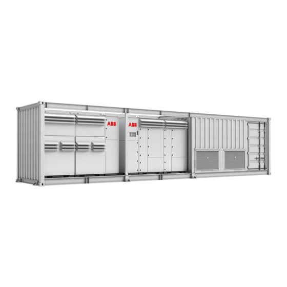
- Page 1 — ABB SOLAR INVERTERS PVS980-MWS megawatt station Hardware manual...
- Page 2 — List of related manuals Hardware manuals and guides Code (English) PVS980 central inverters hardware manual 3AXD50000026013 PVS980 central inverters commissioning and maintenance manual 3AXD50000046782 Firmware manuals and guides PVS central inverters firmware manual 3AXD50000026271 Option manuals and guides ACS-AP-x Assistant control panels user’s manual 3AUA0000085685 Start-up and maintenance PC tool Drive composer user’s manual 3AUA0000094606...
- Page 3 Hardware manual PVS980-MWS megawatt stations Table of contents 1. Safety instructions 5. Mechanical installation 6. Electrical installation 10. Technical data 2018 ABB Oy. All Rights Reserved. 3AXD50000293537 Rev A EFFECTIVE: 2018-07-05...
-
Page 5: Table Of Contents
Table of contents 1. Safety instructions Contents of this chapter ..........9 Use of warnings . - Page 6 Safety ............. . . 33 Required tools .
- Page 7 To clean or replace the intake air filters of the transformer ..... . . 54 To remove the technical floor ..........54 Inverter maintenance .
-
Page 9: Safety Instructions
Safety instructions 9 Safety instructions Contents of this chapter This chapter contains the safety instructions which you must obey when you install and operate the megawatt stations and do maintenance on the megawatt station. Obey these safety instructions to prevent injury or death, or damage to the equipment. Use of warnings Warnings tell you about conditions which can cause injury or death, or damage to the equipment. -
Page 10: Installation, Start-Up And Maintenance Safety
10 Safety instructions Installation, start-up and maintenance safety Obey these safety instructions which when you install, commission and do maintenance on the megawatt station. If ignored, physical injury or death, or damage to the equipment may occur. Only authorized electricians can install, start-up and maintain the megawatt station. The working methods, tools and components must obey the IEC regulations. -
Page 11: Personal Protective Equipment (Ppe)
Safety instructions 11 Personal protective equipment (PPE) Obey all local installation safety standards and rules. This can require the use of arc-proof clothing, arc-proof masks, protective footwear, protective gloves, eye protection and hearing protection. High-power inverter installations have high fault currents. Use appropriate arc-proof clothing (for example, in the US, a rating of 40 cal/cm is required). - Page 12 12 Safety instructions connected to parallel stations, make sure that you also turn the applicable earthing switches to the “earthed” position. • Temporarily ground the switchgear terminals at all possible external power supplies (grid and parallel stations). Refer to the user's manual of the feeding/switchgear device.
-
Page 13: Safety Instructions For The Inverter And Ac Cabinet Compartment
Safety instructions 13 Safety instructions for the inverter and AC cabinet compartment WARNING! Do the procedure before you start the work on the inverter. Ignoring the instructions can cause physical injury or death, or damage to the equipment. 1. Identify the inverter that you need to work on. Read the inverter safety instructions in the PVS980 central inverters hardware manual (3AXD50000026013 [EN]). -
Page 14: Safe Operation
14 Safety instructions Safe operation These warnings are for all personnel who commission, plan the operation, or operate the megawatt station. WARNING! Obey these instructions to prevent injury or death, or damage to the equipment. • Keep all doors of the megawatt station closed during operation. Give the keys only to authorized personnel. -
Page 15: Introduction To The Manual
Contents of this chapter This chapter describes the intended audience and contents of the manual. Applicability This manual is applicable to PVS980-MWS megawatt stations. Target audience This manual is intended for persons who do the work on the megawatt station as follows: •... -
Page 16: Contents Of The Manual
16 Introduction to the manual Contents of the manual Safety instructions – Safety instructions for installation, commissioning, operation and maintenance. Introduction to the manual – Introduction to the manual. Hardware description – The operation principle and construction of the megawatt station. Storing, lifting and transporting –... -
Page 17: Hardware Description
This chapter gives a short description of the PVS980-MWS megawatt station. Product overview The PVS980-MWS megawatt station includes the equipment needed for the connection of a solar power generator to the medium voltage power grid. The station is into a steel structure that can be transported to a site as a sea container. -
Page 18: Layout Drawing (Dry-Type Variant)
18 Hardware description Layout drawing (dry-type variant) 11 12 Compartments Sec. Description Inverter section Transformer enclosure Low-voltage enclosure Medium-voltage enclosure... -
Page 19: Main Components
Hardware description 19 Main components Sec. Description Inverters Lead-through holes for DC cabling from solar generator Terminal for the external DC earthing Transformer Transformer enclosure air inlet Transformer enclosure air outlet Auxiliary cabinet Communication cabinet (optional) Uninterruptible power supply (UPS) (optional) Lead-through holes for external low-voltage cables Lead-through holes for external communication cables Medium-voltage switchgear... -
Page 20: Layout Drawing (Oil-Type Variant)
20 Hardware description Layout drawing (oil-type variant) Compartments Sec. Description Inverter section Transformer enclosure Low-voltage enclosure Medium-voltage enclosure... -
Page 21: Main Components
Hardware description 21 Main components Sec. Description Inverters Lead-through holes for DC cabling from solar generator Terminal for the external DC earthing Transformer Auxiliary cabinet Communication cabinet (optional) Uninterruptible power supply (UPS) (optional) Lead-through holes for external low-voltage cables Lead-through holes for external communication cables Medium-voltage switchgear Lead-through holes for medium-voltage power grid cables... -
Page 22: Main Circuit Diagram
22 Hardware description Main circuit diagram The general single-line diagram depends on the configuration and options of the unit. Refer to drawing 3AES-SH_4600-01-DW01. Description Inverters Transformer Switchgear Auxiliary transformer AC cabinet fan AC cabinet heating External fan 1 (transformer) External fan 2 (transformer) Spare Power socket 1 &... -
Page 23: Switchgear
Hardware description 23 Switchgear The unit is always equipped with medium-voltage switchgear. Type CCV switchgear is used as standard and consists of three modules: • The first C module is the grid-side module with the grid cable terminals, and a disconnecting and earthing switch. -
Page 24: Type Designation Label
24 Hardware description Type designation label The type designation label contains the basic data of the unit. It is located on the inside of the low-voltage compartment door. PVS980-MWS-xxxx-y-zz+options SERIAL NUMBER: NNNN MADE IN SPAIN MANUFACTURED IN 201x Sec. Item... -
Page 25: Option Codes
For more details, see PVS980 Commissioning and maintenance manual and Phoenix contact documentation. Remote monitoring K486 ABB remote Inverter is equipped with an adapter for remote monitoring. The used adapter monitoring is called NETA-21. The adapter is mainly intended for small scale power plants. - Page 26 26 Hardware description Code Name Description F304 The DC potential (positive or negative) grounding is equipped with parallel grounding bypass resistor. This resistor provides back-up higher impedance grounding if with the normal functional grounding would break down. grounding bypass resistor (only with F282 and F283) 8H382...
- Page 27 Hardware description 27 Code Name Description Auxiliary power options G429 Terminals for Protected 3-phase output terminals for connecting an external auxiliary power external transformer. The voltage level for connection is inverter output voltage level. auxiliary The connection is protected with 32 A/30 A (IEC/UL) fuses. Different fuses are transformer available as an engineered option (+P902).
- Page 28 28 Hardware description Code Name Description Testing (inverters only) P945 Full power Inverter is operated with nominal power. burn-in factory test P954 Grid Grid protection factory tests (OV, UV, OF, UF) protection factory tests (OV, UV, OF, P957 Extended Extended grid protection factory tests (OV, UV, OF, UF, regulations) grid protection factory tests...
-
Page 29: Storing, Lifting And Transporting
Storing, lifting and transporting 29 Storing, lifting and transporting Contents of this chapter This chapter tells you how to store, lift, and move the megawatt station. WARNING! Obey these instructions to prevent physical injury or death, or damage to the equipment: •... -
Page 30: Storing The Megawatt Station
30 Storing, lifting and transporting Storing the megawatt station WARNING! To prevent damage to the megawatt station, keep the delivery packaging and protection canvas on for as long as possible until you install the unit. • Always store the megawatt station in the upright position. •... -
Page 31: Lifting The Megawatt Station
Storing, lifting and transporting 31 Lifting the megawatt station • Protect the corners of the megawatt station against shock. • Lift the megawatt station from the four lifting eyes in the upper corners or bottom corners, according to ISO 3874 for HQ 40' type A. •... -
Page 32: Transporting The Megawatt Station
Incoming inspection at arrival Examine the megawatt station for transportation damage. Mark and record any damage and tell the local ABB or ABB sales contact immediately. To prevent corrosion, repair surfaces with damaged paint. Refer to To repair the painted surfaces on page 58. -
Page 33: Mechanical Installation
Mechanical installation 33 Mechanical installation Contents of this chapter This chapter describes the mechanical installation of the megawatt station, and gives instructions on how to select the location and build the foundation for the megawatt station. Always obey the local regulations. Safety Refer to Safety instructions... -
Page 34: Constructing The Foundation
Take into account the required cable bending radius and installation room. • ABB recommends that the service platform around the megawatt station is at least one meter (40 in) wide. Support the megawatt station from the points marked in the footprint layout drawing (refer Dimension drawings on page 63) by using concrete or steel column foundations. -
Page 35: Preparation Of The Ground
Mechanical installation 35 Preparation of the ground 1. Make a hole for the foundation and cabling. 2. Use geotextile to prevent mixing of the installation gravel with the surrounding soil. 3. Put coarse gravel at the bottom of the hole and fine gravel at the top. 4. -
Page 36: Placing The Mws On The Foundations
36 Mechanical installation Placing the MWS on the foundations WARNING! Before you lift the megawatt station onto the foundations, make sure the foundations are well aligned, hardened and stable. 1. Measure the level of the foundation and the tilting of the surface of the surrounding ground around the foundation. -
Page 37: Filling The Pit And Finalizing The Surroundings
Mechanical installation 37 Filling the pit and finalizing the surroundings 1. If required for local frost conditions, add insulation around the column foundations. 2. Fill the hole with fine gravel with a 5 cm/m tilting angle. Leave a 15 cm air gap underneath the megawatt station. -
Page 38: Adding Weather Protection Hoods
38 Mechanical installation Adding weather protection hoods 1. Remove the temporary protectors (1). 2. Add the weather protection hoods (2). -
Page 39: Electrical Installation
Electrical installation 39 Electrical installation Contents of this chapter This chapter has general instructions on earthing and cabling the megawatt station. Obey all local regulations. Refer to the applicable related documentation, such as, the inverter hardware manuals. WARNING! Only an authorized electrician is permitted to install the cabling to the MWS. -
Page 40: Routing The Cables
Make sure that there is at least 500 mm (20 in.) of separation between the power cables and the control cables. • If you need to put extra cables through the megawatt station, speak to your ABB representative. Item Description... -
Page 41: Protective Earthing (Grounding) Inside The Megawatt Station
Electrical installation 41 Protective earthing (grounding) inside the megawatt station The protective earth (PE) terminals or frames of all of the main components in the megawatt station are connected to the two main PE busbars located at the corners of the building. -
Page 42: Connecting The Communication And Auxiliary Cabling (If Equipped)
42 Electrical installation Connecting the communication and auxiliary cabling (if equipped) Refer to the wiring diagrams for communications and the AC cabinet that are delivered with the megawatt station. To connect the cabling: 1. Remove the covers of the cable entries. 2. -
Page 43: Finalizing The Installation
Finalizing the installation 43 Finalizing the installation Contents of this chapter This chapter tells you how to finalize and check the installation of the megawatt station. Obey all local regulations. WARNING! Only an authorized electrician is permitted to install the cabling to the MWS. -
Page 44: Landscaping The Megawatt Station
44 Finalizing the installation Landscaping the megawatt station You can plant suitable bushes around the megawatt station to landscape it. Do not plant trees near the megawatt station. If there are bushes, make sure that the compost base is at least two meters from the megawatt station, and that the fully-grown bushes cannot prevent maintenance access. -
Page 45: Start-Up And Operation
Start-up and operation 45 Start-up and operation Contents of this chapter This chapter describes the start-up procedure of the megawatt station. WARNING! Only an authorized electrician can install the cabling to the MWS. Obey the safety instructions. Refer to Safety instructions on page 9, and the local safety regulations. -
Page 46: Prerequisites For The Start-Up
46 Start-up and operation Prerequisites for the start-up 1. Remove the transportation canvas. Use the protection plates if there is a thunderstorm warning. 2. Remove the sling of the medium-voltage switchgear. 3. Remove silica gel bags from the transformer compartment and auxiliary compartment. Remove silica gel bags also from the inverters. -
Page 47: Start-Up Procedure
Start-up and operation 47 Start-up procedure Task Information Safety WARNING! Obey the safety instructions during the installation and start-up procedure. Refer to chapter Safety instructions on page 9. Only qualified electricians can install and start-up the megawatt station. Pre-check for the switchgear (No voltage) ... -
Page 48: Start-Up Procedure For The Ups (Optional)
48 Start-up and operation Turn the earthing switch at the grid side of the switchgear to the “not earthed” position. Ask the power grid owner to connect the Only authorized personnel are permitted to make the station to the power grid. Wait until the station connection. -
Page 49: Start-Up Procedure For The Ac Cabinet
Start-up and operation 49 Start-up procedure for the AC cabinet Refer to the electrical diagrams of the AC cabinet (3AES-SH-4600-14-SP01) that are delivered with the unit. Start-up procedure: 1. Make sure that all switches and breakers are in the OFF or open position (downstream of the X0 terminal). - Page 50 50 Start-up and operation...
-
Page 51: Maintenance
This chapter contains the preventive maintenance instructions for the megawatt station. The instructions given here are intended for personnel who are trained and certified by ABB to perform these tasks. WARNING! Only an authorized electrician is permitted to do maintenance work on the MWS. -
Page 52: Tightening Torques
52 Maintenance Tightening torques Unless specified otherwise, use the torques given in the tables. Electrical connections Torque Bolts and nuts Steel: A2-70/A4-70/8.8 Brass 0.9 N·m 2.3 N·m 4.5 N·m 8.0 N·m 5.0 N·m 20 N·m 12 N·m 40 N·m 25 N·m 70 N·m 40 N·m 110 N·m... -
Page 53: Maintenance Intervals
For more information on maintenance, contact your local ABB Service representative. Recommended annual maintenance actions ABB recommends that you do these annual inspections to ensure the highest reliability and optimum performance of the unit. Action Description Visually inspect and do maintenance if it is necessary. -
Page 54: To Clean Or Replace The Intake Air Filters Of The Transformer
54 Maintenance To clean or replace the intake air filters of the transformer 1. Loosen and remove the external screws of the ventilation grille. 2. To open the ventilation grille, pull the top edge. 3. Carefully pull the air filter frame from the ventilation grille. -
Page 55: To Clean The Ac Cabinet
Maintenance 55 To clean the AC cabinet WARNING! Do the steps in section Safety instructions for the inverter and AC cabinet compartment on page 13. Ignoring the instructions can cause physical injury or death, or damage to the equipment. 1. Clean the floor plates with a vacuum cleaner. 2. -
Page 56: To Replace The Transformer Room Fans (Dry-Type Transformer Only)
56 Maintenance To replace the transformer room fans (dry-type transformer only) 1. Set the circuit breaker for the fans and signaling to OFF. Prevent accidental closing of the circuit breaker during the maintenance procedure. 2. Disconnect the supply and signaling cabling. -
Page 57: To Replace The Transformer Room Circulation Fan
2. Clean the damaged area and its surroundings. 3. Coat the damaged area with the zinc coat. ABB recommeds Würth Zinc 300 due to the thicker coat. On large areas, you can use Würth Zinc Spray Perfect to ease the work... -
Page 58: To Repair The Painted Surfaces
58 Maintenance To repair the painted surfaces To repair the painted surfaces, you need: • Sand paper • Cleaning towels and liquids (Würth Pro-Clean 0893 140 or equivalent) • Primer below paint on rusted or deeply scratched surfaces: Hempadur Mastic 45880 12170 of 280 microns when wet •... -
Page 59: To Examine And Clean The Grounding Bars And Points
Maintenance 59 To examine and clean the grounding bars and points To clean the grounding components, you need: • Steel wool • Ensto SR1 joint compuond (or equivalent) • 42839 Würth Protective Wax (or equivalent) To examine and clean the grounding bars and points: •... -
Page 60: To Replace The Door Limit Switch
60 Maintenance To replace the door limit switch 1. Open the main circuit breaker of the auxiliary panel. Make sure that the circuit breaker cannot be closed accidentally during the maintenance procedure. 2. Measure to make sure that no voltage is connected to the limit switch door and light line. -
Page 61: Technical Data
@ 50 °C (122 °F) Maximum operational DC voltage 1500 V DC, max Protected DC inputs (parallel) 2x 8 (up to 24 as option) MPPT trackers Output data (AC) Inverter type (2x ABB central PVS980-58- PVS980-58- PVS980-58- PVS980-58- inverter) 1818kVA-I 1909kVA-J... - Page 62 < 3% Power factor compensation (cos φ) Transformer type ABB Vacuum cast coil dry type (AF) or ABB Oil immersed type (ONAN) Medium voltage switchgear type ABB SafeRing, SF6-insulated, DeV, CV or CCV Enclosure Painted steel outdoor enclosure, IP54, C4 corrosion protection...
-
Page 63: Dimension Drawings
Dimension drawings 63 Dimension drawings Contents of this chapter This chapter contains dimension drawings with dimensions in millimeters. -
Page 64: External Grounding Connections
64 Dimension drawings External grounding connections... -
Page 65: Foot Print
Dimension drawings 65 Foot print... -
Page 66: General Layout
66 Dimension drawings General layout... -
Page 67: Typical Single-Line Diagram
Dimension drawings 67 Typical single-line diagram... - Page 68 68 Dimension drawings...
-
Page 69: Further Information
— Further information For more information on ABB products and services for solar applications, navigate to www.abb.com/solarinverters. - Page 70 © Copyright 2018 ABB. All rights reserved. Specifications subject to change without notice.
Need help?
Do you have a question about the PVS980-MWS and is the answer not in the manual?
Questions and answers