Table of Contents
Advertisement
Quick Links
SERVICE MANUAL
CONTENTS
HOW TO USE
WIRING DIAGRAM
BLOCK DIAGRAM
BASIC MODE
AUTO SWING FUNCTION
SERVICE CALL Q & A
Instruction manual
To obtain the best performance, please read this instruction manual completely.
คู ่ ม ื อ การใช ้ ง าน
เพื อได ้รั บ การทํ า งานที ดี ท ี สุ ด โปรดอ่ า นคู ่ ม ื อ อย่ า งละเอี ย ด
<PM NO:0801E>
INDOOR UNIT
RAK-DJ10PCASVX
RAK-DJ13PCASVX
OUTDOOR UNIT
Page 9
Page 11
Page 37
Page 39
Page 41
Page 43
Page 49
Page 52
Page 53
Page 59
Page 60
Page 61
Page 72
Page 111
Page 1~26
หน ้า 27~54
Advertisement
Table of Contents

Related Manuals for Hitachi airHome 400 RAK-DJ10PCASVX


Summary of Contents for Hitachi airHome 400 RAK-DJ10PCASVX
-
Page 1: Table Of Contents
SERVICE MANUAL INDOOR UNIT RAK-DJ10PCASVX RAK-DJ13PCASVX OUTDOOR UNIT CONTENTS SPECIFICATIONS Page 9 HOW TO USE Page 11 CONSTRUCTION AND DIMENSIONAL DIAGRAM Page 37 MAIN PARTS COMPONENT Page 39 WIRING DIAGRAM Page 41 CIRCUIT DIAGRAM Page 43 RAC-DJ10PCASVX PRINTED WIRING BOARD LOCATION DIAGRAM Page 49 RAC-DJ13PCASVX BLOCK DIAGRAM... -
Page 2: Safety During Repair Work
SAFETY DURING REPAIR WORK 1. In order to disassemble and repair the unit in question, be sure to disconnect the power cord plug from the power outlet before starting the work. 2. If it is necessary to replace any parts, they should be replaced with respective genuine parts for the unit, and the replacement must be effected in correct manner according to the instructions in the Service Manual of the unit. - Page 3 WORKING STANDARDS FOR PREVENTING BREAKAGE OF SEMICONDUCTORS 1. Scope The standards provide for items to be generally observed in carrying and handling semiconductors in relative manufacturers during maintenance and handling thereof. (They apply the same to handling of abnormal goods such as rejected goods being returned). 2.
- Page 4 (6) Use a three wire type soldering iron including a grounding wire. Metal plate (of aluminium, stainless steel, etc.) Bare copper wire (for body earth) Working table Resistor 1 M (1/2W) Staple Earth wire Fig. 3. Grounding of the working table Soldering iron Grounding wire Screw stop at the screwed...
- Page 5 CAUTION Slight fl owing noise of refrigerant in the refrigerating cycle is expected to be heard occasionally in quiet or stop operation and it is normal. When it thunders near by, it is recommend to stop the operation and to disconnect the power cord plug from the power outlet for safety.
- Page 6 – 6 –...
- Page 7 – 7 –...
- Page 8 – 8 –...
-
Page 9: Specifications
SPECIFICATIONS (WALL TYPE) TYPE INDOOR UNIT OUTDOOR UNIT INDOOR UNIT OUTDOOR UNIT MODEL RAK-DJ10PCASVX RAC-DJ10PCASVX RAK-DJ13PCASVX RAC-DJ13PCASVX POWER SOURCE 1 PHASE, 50 Hz, 220 -240V 1060 (350 - 1,350) TOTAL INPUT 700 (210 ~ 1,190) TOTAL AMPERES 3.54 - 3.24 5.07 - 4.65 3.5 (0.9 - 4.2) (kW) - Page 10 Direction of Piping Figure showing the Installation of Indoor and Outdoor Unit. CAUTION In case the pipe length is more than the recommended length for chargeless, add refrigerant R32 as below. Do not exceed the maximum pipe length. There are 6 directions allowed, namely, horizontally Factory Chargeless...
-
Page 11: Safety Precaution
SAFETY PRECAUTION Please read the “Safety Precaution” carefully before operating the unit to ensure correct usage of the unit. ● ● Pay special attention to signs of “ Warning” and “ Caution”. The “Warning” section contains matters which, if not observed strictly, may cause death or serious injury. - Page 12 PRECAUTIONS DURING OPERATION The product shall be operated under the manufacturer specifi cation and ● not for any other intended use. Do not attempt to operate the unit with wet hands, this could cause fatal ● accident. When operating the unit with burning equipments, regularly ventilate the ●...
-
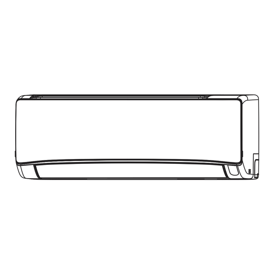
Page 13: Names And Functions Of Each Part
NAMES AND FUNCTIONS OF EACH PART INDOOR UNIT Pre-fi lter To prevent dust from coming into the indoor unit. (Refer page 33) Front panel (Refer page 34) Indoor unit indicators Light indicator showing the operating condition. (Refer page 14) Horizontal defl ector, Vertical defl ector (Air Outlet) Remote controller Send out operation signal to the indoor unit. - Page 14 NAMES AND FUNCTIONS OF EACH PART INDOOR UNIT INDICATIONS Timer Lamp (Orange) Operation Lamp (Yellow) This lamp lights when the timer This lamp lights during operation. is working. Wi-Fi Lamp (Blue) Optional Clean Function Lamp (Green) This lamp uses for FrostWash, Mold Guard, Filter Sign.
- Page 15 NAMES AND FUNCTIONS OF REMOTE CONTROLLER ■ This remote controller controls the operation and timer setting of the room air conditioner. The operating range of the remote controller from the indoor unit is 7m. If indoor lighting is used, the range may be shorter.
-
Page 16: Various Functions
VARIOUS FUNCTIONS ■ Auto Restart Control If there is a power failure, operation will be automatically restarted when the power is resumed with ● previous operation mode and airfl ow direction. (As the operation is not stopped by remote controller.) If you intend not to continue the operation when the power is resumed, switch off the power supply. -
Page 17: Dry Mode
Dry Mode Use the room air conditioner for dehumidifying when the room temperature is over 16°C. When it is under 15°C, the dehumidifying function does not work. Press the Mode Selector button so that the display indicates (Dry). The fan speed is set at Auto. Press (Fan Speed) button to select Silent, Low or Auto fan speed. -
Page 18: Fan Mode
Fan Mode User can use the device simply as an air circulator. Press the Mode Selector button so that the display indicates (Fan) . Press the (Fan Speed) button. (Silent) (Low) (Medium) (Super High) (High) Press the (On/Off) button. Fan operation starts with a beep. START Press the button again to stop operation. -
Page 19: Timer Reservation
Timer Reservation ■ ON Timer and OFF Timer are available. Timer Reservation ■ Operation stops at set time Off Timer setting Select the Off Timer by pressing the Button. ● ● Setting time will change according to the below sequence when you press the button. -
Page 20: Powerful Operation
Powerful Operation By pressing (Powerful) button during Cool, Dry, Fan or Air Circulation, the air conditioner performs at ● maximum power. During Powerful operation, cooler air blows out from the indoor unit for COOLING operation. ● Press the (Powerful) button during operation. “... - Page 21 FrostWash Operation ● The dust and dirt adhere to indoor heat exchanger are some of the causes of the odor. They are washed away by freezing and thawing of the heat exchanger. FrostWash operation can work when the outdoor temperature is 21° to 43°C. ●...
- Page 22 Mold Guard Operation ● After the cooling operation is stopped, the fan of the indoor unit is dried by fan mode to suppress the generation of mold inside the indoor unit. – Mold Guard Operation period is about 1 hour. –...
- Page 23 Refresh Mode Operation To slightly reduce air blow temperature of air conditioner and room humidity if unit has been operating for a long period of time for the day. (a) During COOLING operation, press the to allow unit to start REFRESH Operation.
- Page 24 Power Safe (Max Current Switching) This function limit the maximum current during the operation of air conditioner. It will help to avoid breaker trips if maximum current reaches the breaker limits. In summary, this function limit the electrical current during operation. ■...
-
Page 25: Silent Operation
Silent Operation By pressing the (SILENT) button during Cool, Dry, Fan & Air Circulation operation, the fan speed changes to the silent fan speed When button is pressed, ● START “ ” is displayed on the LCD. ● Fan speed changes to silent ●... - Page 26 GoodSleep Timer Setting Press the button, and the display changes as shown below. Mode Indication 1 hour interval GoodSleep Timer (Cancel GoodSleep Timer) GoodSleep Timer: The device will continue working for the GoodSleep Timer designated number of hours and then turn off. Point the signal window of the remote controller toward the indoor unit, and press the GoodSleep button.
-
Page 27: Adjusting The Air Flow Direction
Adjusting the Airfl ow Direction Adjust the airfl ow upward and downward. According to operation, the horizontal air defl ector is automatically set to the proper angle suitable for each operation. The defl ector can be swings up and down and also set to the desired angle using the “... - Page 28 Initialization of the Built-in airCloud Home Module You can reset the internal settings (restore the factory settings) by remote controller. This operation is valid only for indoor unit with Built-in airCloud Home module. It is invalid when in use with Adapter WiFi module. ■...
- Page 29 How to Exchange the Batteries in the Remote Controller Remove the cover as shown in the fi gure and take out the old batteries. Push and pull to the direction of arrow Batteries Install the new batteries. The direction of the batteries should match the marks in the case. CAUTION 1.
- Page 30 How to Reset Filter Sign on the indoor unit Filter sign on the indoor unit will blink with 1s On and 4s OFF. Because cleaning of Air fi lter has not been done for a long time. Clean the Air fi lter. Press Filter button at Off Mode pointing the remote controller towards the indoor unit to reset Filter Sign.
- Page 31 THE IDEAL WAYS OF OPERATION Suitable Room Temperature Install curtain or blinds It is possible to reduce Warning heat entering the room Freezing temperature is bad for health through windows. and a waste of electric power. Ventilation Do Not Forget To Clean The Pre-Filter Dusty air fi...
- Page 32 ATTACHING THE AIR PURIFYING FILTERS Open the front panel Pull up the front panel by holding it at both sides ● with both hands. Remove the Pre-fi lter Push upward to release the claws and pull out the ● Pre-fi lter. Air purifying fi...
-
Page 33: Maintenance
MAINTENANCE CAUTION Before cleaning, stop operation and switch off the power supply. PRE-FILTER Clean the Pre-fi lter, as it removes dust inside the room. In case the Pre-fi lter is full of dust, the air fl ow will decrease and the cooling capacity will be reduced. Further, noise may occur. Be sure to clean the Pre-fi... -
Page 34: Cleaning Of Front Panel
CLEANING OF FRONT PANEL Remove the front panel and wash with clean water. ● Wash it with a soft sponge. After using neutral detergent, wash thoroughly with clean water. When front panel is not removed, wipe it with a soft dry cloth. ●... -
Page 35: Regular Inspection
■ The following phenomena do not indicate unit FROSTWASH OPERATION failure. It does not wash when outside Refrigerant fl ow noise in the pipe or valve Hissing or fi zzy temperature is less than about 21°C or sounds sound generated when fl ow rate is adjusted. more than 43°C. - Page 36 If the unit still fails to operate normally after performing the Please contact your sales agent immediately if the air above inspections, turn the circuit breaker off and contact conditioner still fails to operate normally after the above your sales agent immediately. inspections.
-
Page 37: Construction And Dimensional Diagram
CONSTRUCTION AND DIMENSIONAL DIAGRAM FOR INDOOR INDOOR UNIT MODEL RAK-DJ10PCASVX, RAK-DJ13PCASVX Unit: mm Indoor unit service space Mounting plate Front Cover Horizontal air deflector Discharge grill About 73 About 270 About 162 V-Deflector – 37 –... - Page 38 MODEL RAC-DJ10PCASVX, RAC-DJ13PCASVX – 38 –...
-
Page 39: Main Parts Component
MAIN PARTS COMPONENT THERMOSTAT Thermostat Specifi cations RAK-DJ10PCASVX, RAK-DJ13PCASVX MODEL THERMOSTAT MODEL OPERATION COOL 16.7 (62.1) INDICATION 16.0 (60.8) TEMPERATURE °C 24.7 (76.5) INDICATION 24.0 (75.2) 32.7 (90.9) INDICATION 32.0 (89.6) FAN MOTOR Fan Motor Specifi cations RAC-DJ10PCASVX RAC-DJ13PCASVX RAK-DJ10PCASVX, RAK-DJ13PCASVX MODEL RATED VOLTAGE DC340V... - Page 40 RAC-DJ10PCASVX, RAC-DJ13PCASVX ASD088CKPA6JK6B 2M = 2.084 ± 7% – – – CAUTION When the Air Conditioner has been operated for a long time with the capillary tubes clogged or crushed or with too little refrigerant, check the color of the refrigerant oil inside the compressor. If the color has been changed conspicuously, replace the compressor.
- Page 41 – 41 –...
-
Page 42: Circuit Diagram
CIRCUIT DIAGRAM Remote controller – 43 –... - Page 43 CIRCUIT DIAGRAM MODEL: RAK-DJ10PCASVX, RAK-DJ13PCASVX – 45 –...
- Page 44 CIRCUIT DIAGRAM RAC-DJ10PCASVX, RAC-DJ13PCASVX MODEL RAC-DH10PCAST RAC-DH13PCAST – 47 –...
-
Page 45: Printed Wiring Board Location Diagram
PRINTED BOARD LOCATION DIAGRAM MODEL: RAK-DJ10PCASVX, RAK-DJ13PCASVX – 49 –... - Page 46 MODEL: RAC-DJ10PCASVX, RAC-DJ13PCASVX Control P.W.B. Marking on P.W.B. (Component side) – 50 –...
- Page 47 MODEL: RAC-DJ10PCASVX, RAC-DJ13PCASVX – 51 –...
- Page 48 – 52 –...
- Page 49 – 53 –...
- Page 50 Notes: (1) Condition for entering into Cool Dashed mode. When fan set to “Hi” or “Auto mode” and temperature difference between indoor temperature and set temperature has a corresponding compressor rpm (calculated value in Table 2) larger than CMAX. (2) Cool Dashed will release when i) a maximum 25 minutes is lapsed and ii) room temperature is lower than set temperature –3°C (thermo off) and iii) when room temperature has achieved setting temperature –1°C then maximum Cool Dashed time will be revised to 20 minutes.
- Page 51 Notes: (1) If the room temperature is (cooling preset temperature) - (1.33°C) or less after 30 seconds from starting the operation, the operation is done assuming as the preset temperature = (room temperature at the time) - (2°C). (2) The indoor fan is operated in the “Lo/Silent” mode. During thermo OFF indoor fan will be OFF for 5 minutes and ON for 1 minute. Indoor fan will go to FWSS (350 rpm). (3) When the operation is started by the themostat turning ON, the start of the indoor fan is delayed 32 seconds after the start of compressor operation.
-
Page 52: Refrigerating Cycle Diagram
REFRIGERATING CYCLE DIAGRAM MODEL: RAK-DJ10PCASVX / RAC-DJ10PCASVX MODEL: RAK-DJ13PCASVX / RAC-DJ13PCASVX – 59 –... - Page 53 – 60 –...
-
Page 54: Description Of Main Circuit Operation
DESCRIPTION OF MAIN CIRCUIT OPERATION MODEL RAK-DJ10PCASVX, RAK-DJ13PCASVX – 61 –... - Page 55 – 62 –...
- Page 56 – 63 –...
- Page 57 – 64 –...
- Page 58 – 65 –...
- Page 59 (Not applicable for this model) – 66 –...
- Page 60 – 67 –...
- Page 61 DESCRIPTION OF MAIN CIRCUIT OPERATION MODEL: RAC-DJ10PCASVX,/ RAC-DJ13PCASVX – 68 –...
- Page 62 – 69 –...
- Page 63 ± ± ± – 70 –...
- Page 64 – 71 –...
- Page 65 – 72 –...
-
Page 66: Procedure For Disassembly And Reassembly
Procedure for Disassembly and Reassembly – 73 –... - Page 67 – 74 –...
- Page 68 MODEL: RAC-DJ10PCASVX/RAC-DJ13PCASVX – 75 –...
-
Page 69: Troubleshooting
TROUBLE SHOOTING MODEL: RAC-DJ10PCASVX RAC-DJ13PCASVX – 76 –... - Page 70 – 77 –...
- Page 71 – 78 –...
- Page 72 – 79 –...
- Page 73 – 80 –...
- Page 74 SELF-DIAGNOSIS LIGHTING MODE MODEL: RAC-DJ10PCASVX, RAC-DJ13PCASVX ± %) ± %) – 81 –...
- Page 75 – 82 –...
- Page 76 – 83 –...
- Page 77 – 84 –...
- Page 78 < > ・ ・ < > ・ ※ – 85 –...
- Page 79 – 86 –...
- Page 80 – 87 –...
- Page 81 Service Setting Item used for GRAC SEA model Category 1: Installation HHRC LCD Display Layer1 Layer2 Layer3 Category Function Name Value Category Function Value Disable Card Key Input - A enable Card Key Card Key Input - B enable Installation reserve 04-99 Auto restart Changeover Disable...
- Page 82 Category 6: HHRC HHRC LCD Display Layer1 Layer2 Layer3 Category Function Name Value Category Function Value Operation Disable selection on HHRC Enable Selection on HHRC Mode: Air Cir Auto Fan Speed Disable selection on HHRC Enable/Disable Enable Selection on HHRC Enable Selection on HHRC Super-Hi Fan HHRC...
- Page 83 – 90 –...
- Page 84 INDOOR INDEPENDENT MODE ONLY – 91 –...
- Page 85 – 92 –...
- Page 86 – 93 –...
- Page 87 – 94 –...
- Page 88 – 95 –...
- Page 89 – 96 –...
- Page 90 – 97 –...
- Page 91 – 98 –...
- Page 92 – 99 –...
- Page 93 – 100 –...
- Page 94 – 101 –...
- Page 95 – 102 –...
- Page 96 – 103 –...
- Page 97 – 104 –...
- Page 98 – 105 –...
- Page 99 – 106 –...
- Page 100 – 107 –...
- Page 101 – 108 –...
- Page 102 – 109 –...
- Page 103 RAC-DJ10PCASVX, RAC-DJ13PCASVX – 110 –...
-
Page 104: Parts List And Diagram
PARTS LIST AND DIAGRAM INDOOR UNIT MODEL : RAK-DJ10PCASVX, RAK-DJ13PCASVX – 111 –... -
Page 105: Parts Name
MODEL RAK-DJ10PCASVX, RAK-DJ13PCASVX PART NO. Q’TY / UNIT PARTS NAME PMK-DJ10PCASV PWB MAIN (RAK-DJ10PCASVX) PMK-DJ13PCASV PWB MAIN (RAK-DJ13PCASVX) PMK-DJ10PCASV PWB RECEIVER PMRAS-EH10CKT CYCLE ASSY PMK-DJ10PCASV FAN MOTOR PMK-DJ10PCASV FRONT COVER ASSY PMK-DJ10PCASV FRONT PANEL PMRAS-EH10CKT AIR FILTER PMK-DJ10PCASV AUTO SWEEP MOTOR PMK-DJ10PCASV TANGENTIAL FAN PMK-DJ10PCASV... - Page 106 PARTS LIST AND DIAGRAM OUTDOOR UNIT MODEL : RAC-DJ10PCASVX – 113 –...
-
Page 107: Rac-Dj10Pcasvx
RAC-DJ10PCASVX MODEL Q’TY / UNIT PART NO. PARTS NAME PMRAC-PH10CMT COMPRESSOR PMRAC-SH10CKT FAN MOTOR PMRAC-XH10CKT SUPPORT (FAN MOTOR) PMC-DH10PCAST CONDENSER PMRAC-X18CGT TERMINAL BOARD (3P) PMRAC-F10CJ PROPELLER FAN PMC-DH10PCAST CABINET PMRAC-EH10CKT D-GRILL PMRAC-EH10CKT TOP COVER PMRAC-EH10CKT SIDE PLATE (R) PMRAC-EH10CKT SIDE PLATE (L) PMRAC-EH10CKT VALVE 3S PMRAC-X13CX... - Page 108 PARTS LIST AND DIAGRAM OUTDOOR UNIT MODEL : RAC-DJ13PCASVX – 115 –...
-
Page 109: Rac-Dj13Pcasvx
RAC-DJ13PCASVX MODEL Q’TY / UNIT PART NO. PARTS NAME PMRAC-PH10CMT COMPRESSOR PMRAC-SH10CKT FAN MOTOR PMRAC-EH10CKT SUPPORT (FAN MOTOR) PMC-DH13PCAST CONDENSER PMRAC-X18CGT TERMINAL BOARD (3P) PMRAC-F10CJ PROPELLER FAN PMC-DH10PCAST CABINET PMRAC-EH10CKT D-GRILL PMRAC-EH10CKT TOP COVER PMRAC-EH10CKT SIDE PLATE (R) PMRAC-EH10CKT SIDE PLATE (L) PMRAC-EH10CKT VALVE 3S PMRAC-X13CX... - Page 110 RAK-DJ10PCASVX / RAC-DJ10PCASVX PM NO. 0801E RAK-DJ13PCASVX / RAC-DJ13PCASVX Printed in Malaysia SPECIFICATIONS AND PARTS ARE SUBJECT TO CHANGE FOR IMPROVEMENT ROOM AIR CONDITIONER INDOOR UNIT + OUTDOOR UNIT Refrigeration & Air-Conditioning Division MARCH 2023...
Need help?
Do you have a question about the airHome 400 RAK-DJ10PCASVX and is the answer not in the manual?
Questions and answers