Table of Contents
Advertisement
Quick Links
INSTALLATION MANUAL
VRF system indoor unit (Cassette type)
For authorized service personnel only.
MANUEL D'INSTALLATION
Appareil intérieur à système VRF (type cassette)
Pour le personnel agréé uniquement.
MANUAL DE INSTALACIÓN
Unidad interior del sistema VRF (Tipo casete)
Únicamente para personal de servicio autorizado.
AUUB12TLAV2
AUUB14TLAV2
AUUB18TLAV2
AUUB24TLAV2
AUUB30TLAV2
AUUB36TLAV2
AUUB48TLAV2
PART No. 9371022666-04
Advertisement
Table of Contents

Related Manuals for Fujitsu AUUB12TLAV2


Summary of Contents for Fujitsu AUUB12TLAV2
- Page 1 For authorized service personnel only. MANUEL D’INSTALLATION Appareil intérieur à système VRF (type cassette) Pour le personnel agréé uniquement. MANUAL DE INSTALACIÓN Unidad interior del sistema VRF (Tipo casete) Únicamente para personal de servicio autorizado. AUUB12TLAV2 AUUB14TLAV2 AUUB18TLAV2 AUUB24TLAV2 AUUB30TLAV2 AUUB36TLAV2 AUUB48TLAV2...
-
Page 2: Table Of Contents
INSTALLATION MANUAL 1.2. SPECIAL PRECAUTIONS PART No. 9371022666-04 VRF system indoor unit (Cassette type) When Wiring ELECTRICAL SHOCK CAN CAUSE SEVERE PERSONAL INJURY OR DEATH. ONLY A Contents QUALIFIED, EXPERIENCED ELECTRICIAN SHOULD ATTEMPT TO WIRE THIS SYSTEM. SAFETY PRECAUTIONS ..................1 •... -
Page 3: About This Product
Washer For installing indoor unit. 2. ABOUT THIS PRODUCT 2.1. Precautions for using R410A refrigerant Insulation For installing drain pipe WARNING Do not introduce any substance other than the prescribed refrigerant into the refrigera- Drain hose For installing drain pipe. tion cycle. -
Page 4: Installation Work
Discharge direction setting 3. INSTALLATION WORK • The discharge direction can be selected as shown below. 4 direction 3 direction Correct initial installation location is important because it is difficult to move unit after it is installed. 3.1. Selecting an installation location Decide the mounting position together with the customer as follows. -
Page 5: Pipe Installation
• Distribution ducts and fresh air inlet positions. 3.3.4. Leveling Unit: in (mm) • Using a level, or vinyl hose filled with water, fine adjust so that the body is level. Distribution duct connecting port Detailed diagram of distribution • Inclined installation so as the drain pipe side is higher may cause a malfunction of the duct connecting port (4 sides) Fresh air inlet float switch, and may cause water leakage. -
Page 6: Flare Connection (Pipe Connection)
4.3. Flare connection (pipe connection) 4.4. Installing heat insulation WARNING CAUTION Tighten the flare nuts with a torque wrench using the specified tightening method. Other- After checking for gas leaks (refer to the Installation Manual of the outdoor unit), perform wise, the flare nuts could break after a prolonged period, causing refrigerant to leak and this section. -
Page 7: Electrical Wiring
Working procedure 6. ELECTRICAL WIRING (1) Install the attached drain hose to the drain port of the body. Install the hose band from the top of the hose within the graphic display area. Secure firmly with the hose WARNING band. (2) Use vinyl adhesive agent to glue the drain piping (PVC pipe VP25) which is prepared Electrical work must be performed in accordance with this Manual by a person certified on site or elbow socket. -
Page 8: Wiring Method
• MAX. CKT. BKR: Maximum Circuit • Before attaching the cable to terminal block. (Fuse capacity) Breaker 6.3.1. Power supply cable AUUB12TLAV2 0.33 A When the power crossover wiring is Conduit connector done, make it so that the total of the... -
Page 9: Connection Of Wiring
6.3.2. Transmission and Remote controller cable (2) Please firmly tighten Connection cable and Remote controller cable with the attached cable tie. Transmission cable Remote controller cable 1-3/16 in (30 mm) 1-3/16 in (30 mm) X1, X2: Transmission cable Shield cable (no film) 1-3/4 in (45 mm) -
Page 10: Optional Parts Wiring
6.5. Optional parts wiring 6.6. External input and external output (optional parts) 6.5.1. Connector and DIP switch position 6.6.1. External input • Indoor unit can be Operation/Stop, Emergency stop or Forced stop by using indoor unit CN67 CNA03 CNB01 CN820 CN65 Controller PCB PCB CNA01 or CNA02. - Page 11 When connected to Dry contact terminals of multiple indoor units with a connected unit, ● Forced thermostat off function (“Edge” input only) insulate each indoor unit with relay, etc. as shown on below example. *If function setting “60” is set to “00” P.C.B Input Connector...
-
Page 12: Field Setting
• Custom code setting for indoor unit 7. FIELD SETTING IU AD REF AD RC AD Set the DIP switch SET3 SW1, 2, referring to the figure and table below. There are 3 methods for address setting by FIELD SETTING as follows. ×10 ×1 ×10... - Page 13 Function Function Function Setting number Default Details Function Setting number Default Details number number When set to 01, the fan stops when Follow the (Prohibited) Fan set- the thermostat is OFF in cooling setting on ting when Standby 00 Disable operation.
-
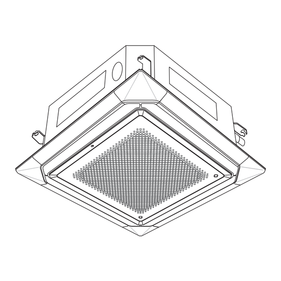
Page 14: Cassette Grille Installation
8. CASSETTE GRILLE INSTALLATION 11. ERROR CODES • Operate according to the installation manual of the Cassette grille. If you use a wired type remote controller, error codes will appear on the remote controller • Be sure to confirm there is no gap between the cassette grille and main unit after install- display.
Need help?
Do you have a question about the AUUB12TLAV2 and is the answer not in the manual?
Questions and answers