
Related Manuals for ROBLIN GRAPHIC MURALE 900


Summary of Contents for ROBLIN GRAPHIC MURALE 900
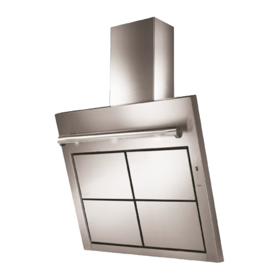
- Page 1 Libretto Istruzioni Instructions Booklet Mode d’emploi Bedienungsanleitung Gebruiksaanwijzing Graphic Murale 900...
- Page 2 Dear Customer, If you follow the recommendations contained in this Instruction Manual, your appliance will give you constant high performance and will remain efficient for many years to come. CONTENTS RECOMMENDATIONS AND SUGGESTIONS CHARACTERISTICS INSTALLATION MAINTENANCE...
-
Page 3: Recommendations And Suggestions
RECOMMENDATIONS AND SUGGESTIONS INSTALLATION • The manufacturer will not be held liable for any damages resulting from incorrect or improper installation. • The minimum safety distance between the cooker top and the extractor hood is 650 mm. • Check that the mains voltage corresponds to that indicated on the rating plate fixed to the inside of the hood. - Page 4 CHARACTERISTICS Dimensions Components Ref. Q.ty Product Components Hood Body, complete with: Controls, Light, Blower, Filters Upper Section (optional) Lower Section (optional) Directional Air Outlet grille Flange (optional) Angle iron (optional) Filter cover Ref. Q.ty Installation Components Upper Chimney Section Fixing Brackets 7.2.1 (optional) Wall Plugs ( 4 optional )
-
Page 5: Installation
INSTALLATION Wall drilling and bracket fixing On the wall, draw • a Vertical line up to the ceiling or upper limit, at the centre of the area in which the Hood is to be fitted; • a Horizontal line at a minimum of 960 mm above the Cooker Top. •... -
Page 6: Mounting The Hood Body
Mounting the hood body • Open the ducting panels. • Disconnect the panel from the hood canopy by sliding the fixing pin lever.(A) • Remove the metal grease filters by turning the handles provided. • Adjust the two screws Vr, on brackets 11a, to a minimum.(B) •... -
Page 7: Flue Assembly
Flue assembly The chimney can only be installed with exhausting hood • Fasten the angle iron 15 to the hood canopy using the screws 12d (2,9 x 9,5) provided. Upper exhaust flue • Slightly widen the two sides of the upper flue and hook them behind the brackets 7.2.1, making sure that they are well seated. -
Page 8: Control Panel
Control Panel The hood can be switched on pushing directly onto the requested speed without firstly having to select 0/1 button. FUNCTIONS 0/1 Light Turns lighting on and off. 0/1 Motor First speed. When pressed for about 1 seconds the motor is switched off. -
Page 9: Maintenance
REMOTE CONTROL (OPTIONAL) The appliance can be controlled using a remote control powered by a 1.5 V carbon-zinc alkaline batteries of the standard LR03-AAA type. • Do not place the remote control near to heat sources. • Used batteries must be disposed of in the proper manner. -
Page 10: Activated Charcoal Filter (Recirculation Version)
Activated charcoal filter (Recirculation version) REPLACING THE ACTIVATED CHARCOAL FILTER • The filter is not washable and cannot be regenerated. It must be replaced when led S1 flashes or at least every 4 months. The alarm signal will only light up when the extractor motor is switched on. - Page 11 Chère Madame, Cher Monsieur, Si vous suivez attentivement les recommandations contenues dans ce mode d’emploi, votre hotte restera toujours efficace, et fournira constamment les mêmes performances. SOMMAIRE CONSEILS ET SUGGESTIONS CARACTERISTIQUES INSTALLATION UTILISATION ENTRETIEN...
-
Page 12: Conseils Et Suggestions
CONSEILS ET SUGGESTIONS INSTALLATION • Le fabricant décline toute responsabilité en cas de dommage dû à une installation non correcte ou non conforme aux règles de l’art. • La distance minimale de sécurité entre le plan de cuisson et la hotte doit être de 650 mm au moins. - Page 13 CARACTERISTIQUES Encombrement Composants Réf. Q.té Composants de Produit Corps Hotte équipé de:Comandes, Lumière,Groupe Ventilateur,Filtres Cheminée Supérieure (si fournie) Cheminée Inférieure (si fournie) Grille orientée Sortie de l’Air Flasque (si fournie) Cornière (si fournie) Couvercle filtrant Réf. Q.té Composants pour l ’installation Brides Fixation Cheminée Supérieure (si 7.2.1 fournies)
- Page 14 INSTALLATION Perçage Paroi et Fixation Brides Tracer sur la Paroi : • une ligne Verticale jusqu’au plafond ou à la limite supérieure, au centre de la zone prévue pour le montage de la Hotte ; • une ligne Horizontale à 960 mm. min. au-dessus des Plaques de Cuisson. •...
- Page 15 Montage Corps Hotte • Ouvrir les panneaux aspirants. • Décrocher le panneau du corps de la hotte, en faisant coulisser le levier du goujon de fixation spécialement prévu.(A) • Enlever les filtres Anti-graisse, en intervenant sur les poignées spécialement prévues. •...
-
Page 16: Branchement Electrique
Montage Cheminée La Cheminée peut être installée uniquement en version aspirante • Fixer la cornière 15 au corps de hotte avec le vis 12d (2,9 x 9,5) fournies. Cheminée supérieure • Elargir légèrement les deux bords latériaux, et les accrocher derrières les brides 7.2.1 ; refermer jusqu’à... - Page 17 UTILISATION Tableau des commandes Il est possible d’allumer la hotte directement à la vitesse demandée en pressant la touche sans devoir d’abord utiliser la touche 0/1. TOUCHE FUNCTIONS 0/1 éclairage Allume et éteint l'éclairage. 0/1 Moteur Allumé Première vitesse. Cette touche permet d’éteindre la hotte en y pressant pour environ 1 secondes.
-
Page 18: Entretien
TELECOMMANDE (FOURNIE SUR DEMANDE) Il est possible de commander cet appareil au moyen d’une télécommande, alimentée avec des piles alcalines zinc- charbon 1,5 V du type standard LR03-AAA. • Ne pas ranger la télécommande à proximité de sources de chaleur. •... - Page 19 Filtre anti-odeur (Version filtrante) REMPLACEMENT FILTRE AU CHARBON ACTIF • Il n’est ni lavable ni régénérable, il faut donc le remplacer quand la del S1 clignote ou bien au moins tous les 4 mois. La signalisation d’Alarme a lieu uniquement lorsque le Moteur d’aspiration est actionné.
- Page 20 Quest’apparecchio è conforme alla norma europea sulla bassa tensione C.E.E. 73/23 relativa alla sicurezza elettrica e alle norme europee: C.E.E. 89/336 relativa alla compatibilità elettromagnetica e C.E.E. 93/68 relativa alla marcatura CE. This appliance conforms to European Low Voltage Directive 73/23/CEE governing electrical safety, European Directive 89/ 336/CEE on Electromagnetic Compatibility and Directive 93/68/CEE regarding CE Marking.
Need help?
Do you have a question about the GRAPHIC MURALE 900 and is the answer not in the manual?
Questions and answers