Table of Contents
Advertisement
Quick Links
Advertisement
Table of Contents

Related Manuals for Nibe CLIMACOOL UWCS30


Summary of Contents for Nibe CLIMACOOL UWCS30
- Page 1 Water-Source MoDuLar cHILLerS INSTALLATION, OPERATION & MAINTENANCE MANUAL Part#: C97B0004N03 | Revised: October 7, 2024 Chillers, Heat Pumps, Heat Recovery, and SHC Heat Pumps & Heat Recovery UW Models: 30-80 Tons 60Hz – R-454B DEMAND ® SIMULTANEOUS HEATING AND COOLING 95B0059N01...
-
Page 2: Table Of Contents
Water-Source MoDuLar cHILLerS – IoM Table of Contents uW Models Introduction Electrical Connections Warnings & Cautions Communications Wiring Model Nomenclature Power Distribution Drawing Physical Data Electrical Data Operating Limits Wiring Diagram Matrix Dimensional Data and Drawings Example Wiring Diagrams Pre-Installation Pre-Startup Rigging and Lifting Procedures Pre-Startup Checklist Form... -
Page 3: General Description
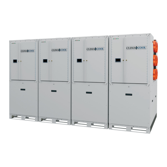
Water-Source MoDuLar cHILLerS – IoM Introduction uW Models GENERAL DESCRIPTION ClimaCool’s Water-Source Modular Chillers, models UWC, UWH, UWT, UWU, & UWW are available in 30, 50, 70, and 80 tons. They can be configured in banks of 1 (one) to 12 (twelve) units (30-960 tons), and can satisfy future incremental growth needs by simply adding modules. -
Page 4: Warnings And Cautions
Water-Source MoDuLar cHILLerS – IoM Warnings & Cautions uW Models WARNING WARNING Do not use means to accelerate the defrosting process Disconnect power supply(ies) before servicing. Refer to clean, other than those recommended by the servicing to qualified service personnel. Electric shock manufacturer. -
Page 5: Model Nomenclature
Water-Source MoDuLar cHILLerS – IoM Model Nomenclature Digits 1-15 uW Models PRODUCT LINE COMPRESSOR SOUND BLANKETS U = Ultimate Chiller 0 = No 1 = Yes SOURCE SCCR W = Water 0 = 5 kAIC APPLICATION 1 = 65 kAIC C = Cooling Only CONTROL OPTIONS H = Heat Recovery... - Page 6 Water-Source MoDuLar cHILLerS – IoM Model Nomenclature Digits 16-30 uW Models HOT GAS SPECIAL INCREMENT BYPASS S = Standard 0 = No 1 = Yes JUNK DRAWER 0 = Off HEAT X = On TRACE 0 = No FUTURE USE COATED COIL FUTURE USE 0 = No...
-
Page 7: Physical Data
Water-Source MoDuLar cHILLerS – IoM Physical Data UWC, UWT, UWH – IP Units uW Models Table 1: UW Series (Imperial Units) Chillers UWC Heat Pumps UWT Heat Recovery UWH Model UW Capacity ( tons ) 30.86 48.12 60.82 76.75 30.33 47.58 60.68 71.31... - Page 8 Water-Source MoDuLar cHILLerS – IoM Physical Data UWU, UWW – IP Units uW Models Table Continued from Previous Page Heat Pumps UWU Heat Recovery UWW Model UW Capacity ( tons ) 30.33 47.58 60.68 71.31 30.33 47.26 59.82 71.31 EER ( Cooling Mode ) 15.830 16.295 15.940...
- Page 9 Water-Source MoDuLar cHILLerS – IoM Physical Data UWC, UWT, UWH – SI Units uW Models Table 2: UW Series (Metric Units) Chillers UWC Heat Pumps UWT Heat Recovery UWH Model UW Capacity ( kW ) 108.53 169.23 213.89 269.92 106.67 167.33 213.40 250.77...
- Page 10 Water-Source MoDuLar cHILLerS – IoM Physical Data UWU, UWW – SI Units uW Models Table Continued from Previous Page Heat Pumps UWU Heat Recovery UWW Model UW Capacity ( kW ) 106.67 167.33 213.40 250.77 106.67 166.21 210.38 250.77 EER ( Cooling Mode ) 15.830 16.295 15.940...
-
Page 11: Operating Limits
Water-Source MoDuLar cHILLerS – IoM Operating Limits uW Models Table 3: Flow and Water Temperature Data – UW 4- & 6-Pipe Heat Pumps & Heat Recovery Cooling Mode Minimum Load Water Flow – gpm [m3/min] 31 [0.12] 48 [0.18] 61 [0.23] 65 [0.25] Maximum Load Water Flow –... - Page 12 Water-Source MoDuLar cHILLerS – IoM Operating Limits uW Models Table 4: Flow and Water Temperature Data – UW 4-Pipe Chillers Evaporator Minimum Chilled Water Flow – gpm [m3/min] 30 [0.11] 47 [0.18] 60 [0.23] 78 [0.30] Maximum Chilled Water Flow – gpm [m3/min] 121 [0.46] 192 [0.73] 244 [0.92]...
-
Page 13: Dimensional Data And Drawings
Water-Source MoDuLar cHILLerS – IoM Dimensional Data and Drawings uW Models 4-Pipe Chillers UWC & Heat Pumps UWT 30, 50, & 70 Ton Control Hot or Hot or Source Source Water Water Outlet Inlet Chilled Chilled Water Water Module Outlet Inlet HMI Screen (Optional) - Page 14 Water-Source MoDuLar cHILLerS – IoM Dimensional Data and Drawings uW Models 4-Pipe Heat Recovery UWH 30, 50, & 70 Ton Water Outlet Water Inlet Chilled Water Chilled Outlet Module Water HMI Screen Control Inlet (Optional) VFD Unit (Optional) Front View Right View 80 Ton Water...
- Page 15 Water-Source MoDuLar cHILLerS – IoM Dimensional Data and Drawings uW Models 6-Pipe SHC Heat Pumps UWU & SHC Heat Recovery UWW 30, 50, & 70 Ton Water Outlet Water Inlet Source Water Source Outlet Water Inlet Chilled Water Chilled Outlet Water Module Inlet...
-
Page 16: Pre-Installation
Water-Source MoDuLar cHILLerS – IoM Pre-Installation uW Models INSPECTION HANDLING OF MODULES Upon receipt of equipment, carefully check the Carefully remove the module’s packaging. The shipment against the bill of lading and inspect each chiller’s steel base cutouts provide maneuverability by chiller for any damage incurred during shipment. -
Page 17: Rigging And Lifting Procedures
Water-Source MoDuLar cHILLerS – IoM Rigging and Lifting Procedures uW Models RIGGING Each module should be lifted by using lift straps threaded through the steel base cutouts and the use of a spreader bar. NOTE: If no spreader bar is used, damage to the unit may occur. Lifting Strap Spreader Bar Spreader Bar... -
Page 18: Recommended Service Clearances
Water-Source MoDuLar cHILLerS – IoM Recommended Service Clearances uW Models Figure 1: Recommended Service Clearance for Sizes 30/50/70/80 Top View Rear Service Access [ 76.2 ] [ 76.2 ] Required Required for Field for Field Piping Piping CoolLogic Touch [ 91.44 ] [ 91.44 ] Control Panel Front Service Access... -
Page 19: Mounting Rails And Vibration Isolation
Water-Source MoDuLar cHILLerS – IoM Mounting Rails and Vibration Isolation uW Models Actual area is 7.25” w x 8.875”h ClimaCool recommends bolting the chiller to a concrete base or two (2) 4-inch (10.16 cm) base mounting rails using the six (6) bolt holes in each base pan. Due to the modules' low vibration, ClimaCool does not require Guides indicate .125”... - Page 20 Water-Source MoDuLar cHILLerS – IoM Mounting Rails and Vibration Isolation uW Models Figure 4: Spring Vibration Isolators Option 4” (10.16 cm) Rail Minimum Recommended (by others) Spring Vibration Isolators (by others) Concrete/Pad (by others) Concrete/Pad (by others) Figure 3: Vibration Isolation Pads Option 4”...
-
Page 21: Assembling Modules
Water-Source MoDuLar cHILLerS – IoM Unit Installation uW Models FOUNDATION FOR UNIT PLACEMENT Field installing the mounting hardware kit will assist in aligning the modules in a bank and eliminate The minimum foundation requirement for the offset inconsistencies. ClimaCool chiller is a level surface capable of bearing Inspect the pipe ends to ensure they are free the combined operating weight of the modules. -
Page 22: Water Piping
Water-Source MoDuLar cHILLerS – IoM Water Piping uW Models PRESSURE DIFFERENTIAL FLOW SENSOR As with any water system, it is important that the system be clean. The pipe work installer must remove It is imperative that minimum and maximum water weld scale, rust and contamination during pipe work flow rates, as defined in the Operating Limits, are not fabrication. - Page 23 Water-Source MoDuLar cHILLerS – IoM Water Piping uW Models PRESSURE TAPS The installing contractor must provide access ports for the ship loose DP Flow and Temperature sensors. UW 4-pipe models require 4-1/4 inch (10.80 cm) pressure taps and 6-pipe models require 6-1/4 inch (15.88 cm) taps.
-
Page 24: Stainless Steel Strainer Option
Water-Source MoDuLar cHILLerS – IoM Stainless Steel Strainer Option uW Models TORQUE SPECIFICATIONS Figure 7: Stainless Steel Strainer Clamped Lid Models: CS strainer models 3CS and 4CS have “over-center latch clamp” lid designs. The over-center clamp does not require adjustment when installing or removing the lid. - Page 25 Water-Source MoDuLar cHILLerS – IoM Stainless Steel Strainer Option uW Models STRAINER OPERATION Step 2. Lift the strainer element (conical screen) out of the strainer body. Periodically, it will be necessary to flush out the Figure 8: Recommended Torquing Sequence debris that is collected and settled at the bottom of the strainer reservoir.
- Page 26 Water-Source MoDuLar cHILLerS – IoM Stainless Steel Strainer Option uW Models ATF OPERATION INSTRUCTIONS Figure 9: Timer Based Valve Controller Flush valve line must be piped to atmospheric pressure such as an open floor drain. The flush line Red Pointer Outer Ring should not undergo any changes in elevation and (Time Between Flushes) should be sloped downward in the direction of...
-
Page 27: Control Switch
Water-Source MoDuLar cHILLerS – IoM Stainless Steel Strainer Option uW Models CONTROL SWITCH ATF WATER RESISTANCE Control switch flushing is initiated by pressing and The valve and controller are water-resistant, not holding down the manual control switch located water-proof. Do not install below ground level on the front of the controller (see Electric Ball Valve where the component can be submerged in on previous page). -
Page 28: Auxiliary Contacts
Water-Source MoDuLar cHILLerS – IoM Stainless Steel Strainer Option uW Models PDA WATER RESISTANCE AUXILIARY CONTACTS The Pressure Differential Alarm Controller is water- The PDA option is equipped with a remote alarm resistant, not water proof. Do not install below ground feature. -
Page 29: Pre-Installation Checklist
Water-Source MoDuLar cHILLerS – IoM WYE Strainer Option uW Models Figure 14: WYE Strainer - Flanged Ends The correct size of the WYE Strainer is determined by its job function, not by the size of the pipeline. PRE INSTALLATION CHECKLIST Ensure working conditions (pressure/temperature) are within the specified capacity of the product being installed. -
Page 30: Maintenance
Water-Source MoDuLar cHILLerS – IoM WYE Strainer Option uW Models MAINTENANCE Figure 15: Bolting Sequence Pattern WYE strainers require little monitoring once they are properly installed. The pressure differential across the strainer should be checked periodically to determine if the screen needs to be cleaned or replaced. - Page 31 Water-Source MoDuLar cHILLerS – IoM WYE Strainer Option uW Models SCREEN REMOVAL/ CLEANING/REPLACEMENT Isolate the strainer by closing the inlet and outlet valve connections on either side of the WYE strainer. Make sure valves are bubble tight. 2. Open vent to relieve pressure inside and drain fluid from the strainer.
-
Page 32: Basket Strainer Option
Water-Source MoDuLar cHILLerS – IoM Basket Strainer Option uW Models The correct size of Basket Strainer is determined by Figure 17: Bolting Sequence Pattern its job function, not by the size of the pipeline. Figure 16: Installed Basket Strainer with Bolted Cover NOTE: Excessive bolt torque may damage flanges. - Page 33 Water-Source MoDuLar cHILLerS – IoM Basket Strainer Option uW Models MAINTENANCE STRAINER ELEMENT CLEANING Basket strainers require little monitoring once they Before removing the cover of the basket strainer, are properly installed. The pressure differential the pressure inside the vessel must be reduced to across the strainer should be checked periodically atmospheric via suction or venting.
-
Page 34: Chiller Header Bypass Kits
Water-Source MoDuLar cHILLerS – IoM Chiller Header Bypass Kits uW Models CHILLER/HEATER SYSTEM WATER HEADER BYPASS A bypass is required for any for any variable flow application per loop. The chiller-bank bypass must be piped in such a way that the temperature and pressure differential flow sensors are still sensing active flow. The purpose of the chiller/heater system bypass is to prevent deadheading of the pumps when all of the internal unit valves go closed as well as allow temperature and differential pressure sensors to sense active flow. - Page 35 Water-Source MoDuLar cHILLerS – IoM Chiller Header Bypass Kits uW Models Middle Pipes (4-pipe Cooling Only; Bottom Pipes (All Applications): 6-pipe heat recovery; 4- & 6-pipe heat pump): Using a 3-inch grooved coupling (C29B0003N04), Using a 3-inch grooved coupling (C29B0003N04), connect 90°...
-
Page 36: Water Piping Configurations
Water-Source MoDuLar cHILLerS – IoM Water Piping Configurations uW Models Figure 19: Field Piping Direct Return – 1 to 5 Modules LEGEND A. Sensor Location 36”–60“ Temp Sensor Well Flow C. Isolation Valve D. Pump Strainer Flow Header Bypass Valve G. -
Page 37: Filling The Water System
Water-Source MoDuLar cHILLerS – IoM Filling the Water System uW Models CLEANING THE SYSTEM It is imperative that the water systems are free from debris prior to initial operation. See Water Quality The following method is recommended to properly Parameters for a comprehensive list of precautions. clean the water systems: FILLING, PURGING AND Before cleaning the system, install a temporary... - Page 38 Water-Source MoDuLar cHILLerS – IoM Filling the Water System uW Models STARTING THE PUMPS Follow the manufacturer’s recommendations when starting the pumps for the first time. The system should be checked for leaks and air purged with the pumps in operation. The pressure drop across the heat exchangers will give a good indication of flow through the system (see project selection print- out or contact local representative).
-
Page 39: Water Treatment & Temperature Requirements
Water-Source MoDuLar cHILLerS – IoM Water Treatment & Temperature Requirements uW Models Water quality is of the utmost importance for the proper care and maintenance of the modular chiller system. Proper water treatment is a specialized industry and it is recommended to consult an expert in this field to analyze the water for compliance with the water quality parameters listed. -
Page 40: Electrical Connections
Water-Source MoDuLar cHILLerS – IoM Electrical Connections uW Models FIELD CONNECTIONS TO THE The power for all modules is taken from a suitable circuit breaker/fused disconnect power supply within COOLLOGIC TOUCH CONTROL SYSTEM the main panel. Proper grounding of the module is Field integration with CoolLogic Touch Control mandatory. -
Page 41: Module Controller
Water-Source MoDuLar cHILLerS – IoM Electrical Connections uW Models MODULE CONTROLLER PROPER VOLTAGE BALANCE The module controller LS1628 directly senses the Occasionally, in three phase circuits, a voltage control parameters that govern the specific module’s imbalance occurs between phases. It is not operation, such as evaporator and condenser recommended to operate equipment when an leaving temperatures, suction and discharge... -
Page 42: Communications Wiring
Water-Source MoDuLar cHILLerS – IoM Communications Wiring uW Models AVOIDING NOISE CHARACTERISTICS OF CAT 5e Avoid running communication wires or sensor input The use of balanced lines helps preserve a high wires next to AC power wires or the controller’s relay signal-to-noise ratio despite interference from both output wires. -
Page 43: Power Distribution Drawing
Water-Source MoDuLar cHILLerS – IoM Power Distribution Drawing Actual area is 7.25” w x 8.875”h uW Models Guides indicate .125” bleed all around Figure 22: Power Distribution Drawing 115V 1PH Typical Module Power Feed (15.0 Amps Minimum) Breaker Control 460V 3PH Panel Panel Main Power Feed... -
Page 44: Electrical Data
Water-Source MoDuLar cHILLerS – IoM Electrical Data uW Models Voltage Limitations The following voltage limitations are absolute and operation beyond these limitations may cause serious damage to the compressor. Nominal Voltage Minimum Voltage Maximum Voltage 208/230-3-60 460-3-60 575-3-60 Power Wiring per Module ClimaCool Voltage Rated Load... -
Page 45: Wiring Diagram Matrix
Water-Source MoDuLar cHILLerS – IoM Wiring Diagram Matrix Including All Electrical Options uW Models Chillers (UWC) Single Auto Wire Diagram Number kaIC Voltage VFD Module Stand Rating 30 Tons 70 Tons 70 Tons 80 Tons Controls Alone 5 kAIC 65 kAIC 5 kAIC 65 kAIC 5 kAIC... - Page 46 Water-Source MoDuLar cHILLerS – IoM Wiring Diagram Matrix Including All Electrical Options uW Models Heat Recovery (UWH) Single Auto Wire Diagram Number kaIC Voltage VFD Module Stand Rating 30 Tons 50 Tons 70 Tons 80 Tons Controls Alone 5 kAIC 65 kAIC 5 kAIC 65 kAIC...
- Page 47 Water-Source MoDuLar cHILLerS – IoM Wiring Diagram Matrix Including All Electrical Options uW Models Heat Pumps (UWT) Single Auto Wire Diagram Number kaIC Voltage VFD Module Stand Rating 30 Tons 70 Tons 70 Tons 80 Tons Controls Alone 5 kAIC 65 kAIC 5 kAIC 65 kAIC...
- Page 48 Water-Source MoDuLar cHILLerS – IoM Wiring Diagram Matrix Including All Electrical Options uW Models SHC Heat Pumps (UWU) Single Auto Wire Diagram Number kaIC Voltage VFD Module Stand Rating 30 Tons 70 Tons 70 Tons 80 Tons Controls Alone 5 kAIC 65 kAIC 5 kAIC 65 kAIC...
- Page 49 Water-Source MoDuLar cHILLerS – IoM Wiring Diagram Matrix Including All Electrical Options uW Models SHC Heat Recovery (UWW) Single Auto Wire Diagram Number kaIC Voltage VFD Module Stand Rating 30 Tons 70 Tons 70 Tons 80 Tons Controls Alone 5 kAIC 65 kAIC 5 kAIC 65 kAIC...
-
Page 50: Example Wiring Diagrams
Water-Source MoDuLar cHILLerS – IoM Example Wiring Diagrams uW Models UWU, SHC Heat Pumps, 208/230V-3PH with Lead VFD PA G E : 5 0 r e v i s e d : o c t o b e r 7, 2 0 2 4 w w w. - Page 51 Water-Source MoDuLar cHILLerS – IoM Example Wiring Diagrams uW Models UWT, Heat Pumps, 208/230V-3PH w w w. c l i m a c o o l c o r p . c o m r e v i s e d : o c t o b e r 7, 2 0 2 4 PA G E : 5 1...
- Page 52 Water-Source MoDuLar cHILLerS – IoM Example Wiring Diagrams uW Models UWUW SHC Heat Recovery with Lead VFD & KAIC, 208/230V-3PH PA G E : 5 2 r e v i s e d : o c t o b e r 7, 2 0 2 4 w w w.
- Page 53 Water-Source MoDuLar cHILLerS – IoM Example Wiring Diagrams uW Models CoolLogic Touch w w w. c l i m a c o o l c o r p . c o m r e v i s e d : o c t o b e r 7, 2 0 2 4 PA G E : 5 3...
-
Page 54: Pre-Startup
Water-Source MoDuLar cHILLerS – IoM Pre-Startup uW Models All startups must be performed by ClimaCool factory Verify that a separate 115 volt power supply is trained personnel. Prior to chiller startup, there are used to power the CoolLogic Touch Bank Control certain essential checks which must be completed. -
Page 55: Water System
Water-Source MoDuLar cHILLerS – IoM Pre-Startup uW Models WATER SYSTEM WARNING Confirm installation of the mandatory field Disconnect power supply(ies) before servicing. Refer installed chilled water strainer with minimum of servicing to qualified service personnel. Electric shock hazard. May result in injury or death! 40 mesh screen. -
Page 56: Pre-Startup Checklist Form
Water-Source MoDuLar cHILLerS – IoM Pre-Startup Checklist Packaged Water-Source Modular Chillers Model: uW Pre-Startup Checklist Form uW Models E-mail: technicalsupport@climacoolcorp.com • Phone: 800.299.9747, Option 2, then Option 3 Project Name: Date: Address/Phone: Are modules connected properly per Codes and Installation Manual? (Installation, Operation &... -
Page 57: Startup Documentation
Water-Source MoDuLar cHILLerS – IoM Mechanical Startup uW Models All startups must be performed by ClimaCool factory 5. Use refrigerant gauge set suitable for the high trained personnel. pressure R-454B, and hook up to the suction and discharge ports of each module’s compressor STARTUP DOCUMENTATION stages separately. -
Page 58: Controller Startup
Water-Source MoDuLar cHILLerS – IoM Controller Startup uW Models CONTROL SYSTEM STARTUP Verify the communication with the Cat5e or 6. For Constant Flow Cooling applications, set higher Ethernet home run cabling is wired to each modules to CV Cooling and confirm that valves unit to and from the CoolLogic Touch Control travel to 100% open. -
Page 59: Electronic Expansion Valves Startup
Water-Source MoDuLar cHILLerS – IoM Electronic Expansion Valves Startup uW Models INSTALLATION 2. Press UP/DOWN to move to the between parameters for Driver A, indicated by the letter at Remove EXV controller face plate. the top right. 2. Install EVO display. a. - Page 60 Water-Source MoDuLar cHILLerS – IoM Electronic Expansion Valves Startup uW Models 8. Check that the electrical connections are correct for Valve A Actual area is 3.5313” w x 8.875”h Guides indicate .125” bleed all around 12. Set Power Supply Mode to 24VDC Parameter/Description Def.
-
Page 61: Startup And Warranty Registration
Water-Source MoDuLar cHILLerS – IoM Startup and Warranty Registration Water-Source Modular Chillers Model: uW Startup and Warranty Registration Sign date and E-mail to: technicalsupport@climacoolcorp.com • For any questions, call 800.299.9747, Option 2, then Option 3 uW Models NOTE: Please fi ll out this form and include the required screenshots for each module in the bank. Project Name: Ambient Temp: Address:... - Page 62 Water-Source MoDuLar cHILLerS – IoM Startup and Warranty Registration uW Models TAKING SCREENSHOTS ON THE COOLLOGIC TOUCH Insert a USB drive into the USB port on the back of the touchscreen. Go to the screens displayed on this page and press the Camera icon to take screenshots of each screen.
-
Page 63: Operation And Maintenance
Water-Source MoDuLar cHILLerS – IoM Operation and Maintenance uW Models PRESSURE AND TEMPERATURE LOG QUARTERLY A log of temperatures and pressures should be taken Check controller operating parameters and setpoints. regularly. Periodically conduct a visual inspection Check temperature drop/rise on heat exchanger.* of the chiller to identify problems before they reach Check compressor oil level. - Page 64 Water-Source MoDuLar cHILLerS – IoM Operation and Maintenance uW Models WINTER SHUTDOWN: WARNING AT THE END OF THE COOLING SEASON WATER AND REFRIGERANT SYSTEMS UNDER PRESSURE Isolate/Lockout source and relieve pressure Drain the fluid from the cooler, hydronic package (if BEFORE servicing equipment.
-
Page 65: Heat Exchangers
Water-Source MoDuLar cHILLerS – IoM Heat Exchangers uW Models DRAINING CHEMICAL CLEAN IN PLACE WASHING WITH WATER ISOLATION VALVES When performing standard maintenance procedures such as flushing a heat exchanger, it will be necessary Chemical Clean in place washing will typically to close off a section of a module. -
Page 66: Cleaning Arrangements
Water-Source MoDuLar cHILLerS – IoM Cleaning Arrangements uW Models Figure 23: City Water Cleaning Arrangement Service Port (3/4”, 1.91 cm) Connection to City Water To Cooling Tower or Source Loop Refrigerant Circuit #1 Header Pete’s Ports Isolation Ball Valves (2, 2-1/2, 3”; 5.08, 6.35, 7.62 cm) Header From Cooling Tower or Source Loop Refrigerant... -
Page 67: Troubleshooting Guide
Water-Source MoDuLar cHILLerS – IoM Troubleshooting Guide uW Models WARNING! WARNING The troubleshooting guidelines recommended in this section could result in exposure to electrical safety Disconnect power supply(ies) before servicing. Refer hazards. Please refer to the safety warnings provided in servicing to qualified service personnel. - Page 68 Water-Source MoDuLar cHILLerS – IoM Troubleshooting Guide uW Models Table continued from previous page. Low discharge pressure Raise and control discharge pressure within design limits. Issue Compressor High Discharge Pressure Alarm: Discharge pressure > 575 psi Possible Cause Solution Use an ample sized cleanable strainer in the condenser water circuit; make certain the strainer is clean to ensure full flow of condenser water (strainer must be 60 mesh Improper condenser water circulation minimum).
- Page 69 Water-Source MoDuLar cHILLerS – IoM Troubleshooting Guide uW Models Table continued from previous page. Bad OAT Sensor Replace sensor. Incorrect wiring to OAT sensor Verify sensor wiring. Issue Invalid Compressor Discharge Temperature Out of Range Alarm: Sensor is reading a value outside of its operating range, while operating inside range Possible Cause Solution Bad discharge temp sensor...
-
Page 70: Refrigerant Recovery, Evacuation, And Charging
Water-Source MoDuLar cHILLerS – IoM Refrigerant Recovery, Evacuation, and Charging uW Models RECOVERY AND EVACUATION CHARGING PROCEDURES When breaking into the refrigerant circuit to make In addition to conventional charging procedures, the repairs - or for any other purpose - conventional following requirements shall be followed. - Page 71 Water-Source MoDuLar cHILLerS – IoM Refrigerant Recovery, Evacuation, and Charging uW Models DECOMMISSIONING RECOVERY Before carrying out this procedure, it is essential When removing refrigerant from a system, that the technician is completely familiar with the either for servicing or decommissioning, it is equipment and all its detail.
-
Page 72: Warranty
Water-Source MoDuLar cHILLerS – IoM Warranty uW Models PA G E : 7 2 r e v i s e d : o c t o b e r 7, 2 0 2 4 w w w. c l i m a c o o l c o r p . c o m... - Page 73 Water-Source MoDuLar cHILLerS – IoM Notes uW Models w w w. c l i m a c o o l c o r p . c o m r e v i s e d : o c t o b e r 7, 2 0 2 4 PA G E : 7 3...
- Page 74 Water-Source MoDuLar cHILLerS – IoM Notes uW Models PA G E : 74 r e v i s e d : o c t o b e r 7, 2 0 2 4 w w w. c l i m a c o o l c o r p . c o m...
- Page 75 Water-Source MoDuLar cHILLerS – IoM Notes uW Models w w w. c l i m a c o o l c o r p . c o m r e v i s e d : o c t o b e r 7, 2 0 2 4 PA G E : 7 5...
-
Page 76: Revision History
Water-Source MoDuLar cHILLerS – IoM Revision History uW Models Date Section Action 10/07/24 Pre-startup Checklist Updated checklist items Updated naming conventions for units and the CoolLogic Touch Control System Chiller Header Bypass Kits Updated Return Header Graphics, Added Header Bypass Kit instructions 09/23/24 Water Piping Configurations Noted some components optional...
Need help?
Do you have a question about the CLIMACOOL UWCS30 and is the answer not in the manual?
Questions and answers