Table of Contents
Advertisement
Quick Links
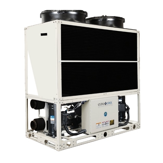
Packaged Air Cooled Modular Chiller
Water Cooled, Heat Pump, Heat Recovery, Free Cooling and
Simultaneous Heating & Cooling Heat Pump
Model UCA: 20, 30, 50 and 70 tons
Installation, Operation & Maintenance Manual
Doc#: 97B0089N01 | Rev: May 5, 2023
•
•
on
DEMAND
SIMULTANEOUS HEATING AND COOLING
95B0059N01
®
Advertisement
Table of Contents

Related Manuals for Nibe CLIMA COOL UCA 20


Summary of Contents for Nibe CLIMA COOL UCA 20
- Page 1 Packaged Air Cooled Modular Chiller Water Cooled, Heat Pump, Heat Recovery, Free Cooling and Simultaneous Heating & Cooling Heat Pump Model UCA: 20, 30, 50 and 70 tons Installation, Operation & Maintenance Manual • • DEMAND ® SIMULTANEOUS HEATING AND COOLING 95B0059N01 Doc#: 97B0089N01 | Rev: May 5, 2023...
-
Page 2: Table Of Contents
Table of Contents Introduction . . . . . . . . . . . . . . . . . . . . . . . . . . . . . . . . . . . . . . . . . 1 Startup . -
Page 3: Introduction
Introduction General Description ATTENTION ClimaCool’s Air Cooled Packaged Modular Chiller, Model Confirm all panels and electrical covers are properly installed/sealed, UCA, are available in 20, 30, 50 and 70 tons and can be including the condenser fan motor cover. configured to provide project turndown and capacity WARNING/ADVERTISSEMENT requirements from 20 to 420 tons . -
Page 4: Pre-Installation
Pre-Installation Inspection Rigging and Lifting Upon receipt of equipment, carefully check the shipment Each module should be lifted by using a fork lift . If it is against the Bill of Lading and inspect each chiller for any necessary to utilize a crane for rigging or lifting each module damage incurred during shipment . -
Page 5: Model Key
Model Key Rev: May 5, 2023 www.climacoolcorp.com... -
Page 6: Physical Data
Physical Data Cooling Only Heat Pump Model UCA Capacity (Tons) 18.4 27.5 17.9 26.7 17.9 26.7 10.3 10.3 9.97 9.97 9.97 9.97 Refrigerant Circuits (quantity) Compressor Type scroll scroll scroll scroll scroll scroll Compressor Quantity Compressor Nominal Hp (per circuit) Refrigerant Charge R-410A (lbs) Module Operating Weight w/Water (lbs) 2,250... - Page 7 Physical Data Cooling Only Heat Pump Model UCA Capacity (Tons) 44.0 62.7 41.4 59.0 41.4 59.0 10.5 10.1 9.88 9.601 9.88 9.601 Refrigerant Circuits (quantity) Compressor Type Scroll Scroll Scroll Scroll Scroll Scroll Compressor Quantity Compressor Nominal Hp (per circuit) Refrigerant Charge R-410A (lbs) Module Operating Weight w/Water (lbs) 4,101...
- Page 8 Physical Data Free Cooling Free Cooling Fans Motor Type T.E. T.E. Quantity Fan Type Axial Axial Diameter 31.5 31.5 Airflow (CFM per circuit) 21,000 42,000 1,100 1,100 Free Cooling Coils Fin Material Aluminum Aluminum Tube Material Copper Copper Dimensions (Quantity) 20”...
-
Page 9: Dimensional Data And Drawings
Dimensional Data and Drawings Figure 1 - Cooling Only, UCA 020 & 030 Discharge Discharge Discharge Air Intake Chilled Water Inlet Control Control Chilled Water Air Intake Outlet UCA 020 UCA 030 Header Model Header Header Voltage Unit Width Unit Height Unit Depth Connection Location... - Page 10 Dimensional Data and Drawings Figure 3 - Simultaneous Heating & Cooling 020 & 030 Discharge Discharge Discharge Chilled Water Air Intake Inlet Chilled Water Outlet Water Outlet Control Control Water Air Intake Inlet UCA 020 UCA 030 Header Model Header Header Header Header...
- Page 11 Dimensional Data and Drawings Figure 5 - Free Cooling, UCF 030 Discharge Discharge Air Intake Chilled Water Inlet Control Chilled Water Air Intake Outlet Header Model Header Header Header Voltage Unit Width Unit Height Unit Depth Connection Location Location Location (in.) (in.) (in.)
-
Page 12: Rigging And Lifting Procedures
Rigging and Lifting Procedures Rigging Each module should be lifted by using lift straps threaded through the steel base cutouts and the use of a spreader bar . NOTE: If no spreader bar is used, damage to the unit may occur. Figure 7 Figure 8 Lifting Strap... -
Page 13: Mounting Rail And Vibration Isolation
Mounting Rail and Vibration Isolation ClimaCool recommends locking down the chiller to a concrete base or with the two (2) 4” base mounting rails using the six bolt holes provided in each base pan (see Figure 10) . Due to the low vibration of the modules, ClimaCool does not require the application of spring isolators or pads . - Page 14 Mounting Rail and Vibration Isolation Figure 11 - Spring Vibration Isolators Option 4” Rail Minimum Recommended (by others) Spring Vibration Isolators (by others) Concrete / Pad (by others) Concrete / Pad (by others) Figure 12 - Vibration Isolation Pads Option 4”...
-
Page 15: Recommended Service Clearances
Recommended Service Clearances Figure 13 - End-to-End Configuration for UCA020 or 030 sizes only Top View 36” 36” Rear Service Access See Note See Note 6 for side 6 for side clearance clearance Air Intake Air Intake 42” Service and Air Intake Clearance Figure 14 - Back-to-Back Configuration Service and Air Intake... -
Page 16: Unit Installation
Unit Installation Foundation for Unit Placement Field installing the mounting hardware kit will assist with alignment of the modules in a bank and eliminate The minimum foundation requirement for the ClimaCool offset inconsistencies. The arrows in Figure 16, page 15 chiller is a level surface capable of bearing the combined show the end to end and back to back holes for the 1”... - Page 17 Unit Installation Figure 15 - Hardware Kit Figure 17 - Back to Back Header Insulation Chilled water piping is pre-insulated on each module at the factory with 3/4” closed cell insulation . After bolting all modules together and leak testing, the entire coupling Figure 16 - Spacer Holes connection will need to be insulated by the installing contractor.
-
Page 18: Electrical Connections
Electrical Connections The power for modules is taken from a suitable circuit The voltage imbalance of the three phase circuit is 0 .9% . breaker/fused disconnect power supply within the main This is well under the 2% range . panel . The electrical service enters the individual modules through the upper right side of the module’s control panel Voltage/Phase Monitor enclosure . -
Page 19: Communications Wiring
Communications Wiring Avoiding Noise* WARNING/ADVERTISSEMENT Avoid running communication wires or sensor input For field installation of Port 1 Pour l’installation sur place du wires next to AC power wires or the controller’s relay communication wiring, installer must câblage de communication du port 1, output wires . -
Page 20: Wiring Diagram-Voltage/Phase Monitor
Wiring Diagram-Voltage/Phase Monitor Rev: May 5, 2023 www.climacoolcorp.com... -
Page 21: Water Piping
Water Piping Pressure Taps As with any water system, it is important that the system be clean . The pipe work installer must remove weld scale, The installing contractor must provide access ports for rust and contamination during pipe work fabrication . connecting the pressure differential flow temperature The system water piping must be flushed thoroughly sensors and pressure gauges for the chilled water system . - Page 22 Water Piping Chiller/Heater System Water Header Bypass Figure 18 - Reverse Return A bypass is required for any load cooling, cooling only and Hose Kit Hose Kit load cooling and load heating, simutaneous heating and cooling heat pump with variable pumping . The chiller bank bypass must be piped in such a way that the temperature END VIEW and pressure differential flow sensors are still sensing...
-
Page 23: Water Piping Configurations
Water Piping Configurations Figure 20 - Field Piping Direct Return - 1 to 5 Modules Figure 21 - Field Piping Reverse Return -(Preferred 1 to 5 modules) Required for 6 or more modules NOTES: 1. Figures 20 and 21 are required piping for proper water regulation and distribution through ClimaCool modular chillers . 2. -
Page 24: Hydronic Refrigeration
Hydronic Refrigeration Figure 22 - Chilled Water Circuit Refrigerant Circuit #1 Service Ports (3/4”) Refrigerant Circuit #2 Isolation Ball Valves Leaving Chilled Water (2 or 2-1/2”) Temperature Sensor Pete’s Ports Heat Exchanger NOTE: Figure 22 depicts hydronic piping in each ClimaCool chiller module and is shown with water isolation valves . Rev: May 5, 2023 www.climacoolcorp.com... -
Page 25: Part-Load Performance Advantage
Part-Load Performance Advantage Figure 23 Water In (Hot) Coil design provides optimum performance in both Full and Partial Load Refrigerant Refrigerant Circuit 1 Circuit 2 Water Out (Cold) Refrigerant Circuit 2 Only If circuit 1 is cut, the unique ClimaCool modular chillers employ reliable and highly design allows each water efficient brazed plate heat exchangers. -
Page 26: Filling The Water System
Filling the Water System Cleaning the System It is imperative that the water systems are free from debris prior to initial operation . See Water Treatment The following method is recommended to properly clean for a comprehensive list of precautions on page 25 . the water systems: Filling, Purging and Leak Testing the System Before cleaning the system, install a temporary bypass... -
Page 27: Water Treatment
Water Treatment Water quality is of the utmost importance for the proper Table 1 - Water Quality Parameters care and maintenance of the modular chiller system. Water Containing Concentration Proper water treatment is a specialized industry and it is recommended to consult an expert in this field to analyze Ammonia Less than 2.0 mg/l the water for compliance with the water quality parameters... -
Page 28: Water Temperature Requirements
Water Temperature Requirements Table 2 - Water Temperature Requirements Load Loops Minimum LWT Maximum LWT Water Chilled Water 20°F 62°F Temperature Limits 135°F Hot Water 90°F (at 40°F ambient or above) NOTES: 1 . Operating in ambient temperatures below 36°F requires a suitable antifreeze solution . 2 . -
Page 29: Operating Limits
Operating Limits Table 4 - Voltage Limitations Table 5 - Compressor Operating Limitations Voltage Limitations Compressor Operating Limitations Maximum Compression Ratio 5.7:1 The following voltage limitations are absolute and operation beyond these Minimum Operating Pressure Differential (psi) limitations may cause serious damage to the compressor. Maximum Operating Pressure Differential (psi) Nominal Voltage Minimum Voltage... -
Page 30: Pre-Startup
Pre-Startup All startups must be performed by ClimaCool factory trained 3. Confirm that necessary water treatment systems are in personnel. Prior to chiller startup, there are certain essential place with the evaporator water systems . checks which must be completed . Failure to carry out these 4. -
Page 31: Pre-Startup Check List
Pre Start-Up Checklist* (Packaged Air-Cooled) UCA E-mail technicalsupport@climacoolcorp.com • Phone: 405.815.3000 Project Name: Date: Address/Phone: Are modules connected properly per Codes and Installati on Manual? (Installati on, Operati on & Maintenance (IOM) Manual is available at www.climacoolcorp.com). Is there a 60 mesh strainer on the inlet water of each loop? (4 pipe SHC has two (2) loops) (Fill water to chiller being sure to pass through a minimum of 60 mesh strainer). -
Page 32: Startup
Startup All startups must be performed by ClimaCool factory 10 . Confirm that the main water pumps are driven by VFD’s, trained personnel. and that all VFD’s are controlling the pump speeds to produce a nominal differential pressure drop across Review all items are complete from the Pre Startup the chiller bank headers, measured precisely at the Checklist . - Page 33 Startup 18 . Use refrigerant gauge set suitable for the high pressure Verify proper superheat by subtracting the saturated R-410A, and hook up to the suction and discharge ports evaporative temperature from the suction line temperature . of each module’s compressor stages separately . Bump The saturated evaporative temperature is found by start the compressors either by depressing the contactor converting the suction pressure reading on the manifold...
-
Page 34: Superheat & Subcooling Flow Chart
Superheat & Subcooling Flow Chart Compressor for 5 Minutes Is Superheat in Range? Is Superheat Is Subcooling Low or High? in Range? High Recheck Superheat Turn TXV Is Subcooling Is Subcooling and Complete Adjustment Low or High? Low or High? Start-up and Stem Clockwise Warranty Form... -
Page 35: Startup And Warranty Registration Form
Startup and Warranty Registration Form (Pkg Air-Cooled UCA) Ambient Sign, date and E-mail to: technicalsupport@climacoolcorp.com 1 of 1 Temp: Page: For any questions, call 405.815.3000/ Option 2, then Option 3 Project Name: Contractor Name: Address: Address: City/State/Zip: City/State/Zip: Startup Date: Phone No: Module Compressor... -
Page 36: Operation And Maintenance
Operation and Maintenance Pressure and Temperature Log Consult the bank performance sheet for your specific project for these values. If the temperature A log of temperatures and pressures should be taken drop/rise is greater than the design, your heat regularly . Periodically conduct a visual inspection of the exchanger may need to be back flushed or the chiller to identify problems before they reach the point strainer may need to be cleaned . - Page 37 Operation and Maintenance Annual WARNING/ADVERTISSEMENT • Back flush all heat exchangers. If fouling is suspected, use only ClimaCool recommended de-scalers (see page 38 - Chemical Clean In Place Washing) . • Remove and clean all waterside strainers . • Manually operate all waterside isolation valves, if WATER AND REFRIGERANT EAU ET FRIGORIGÈNE provided, on each module .
-
Page 38: Condenser Fans
Condenser Fans • Highly efficient, variable speed electrically commutated The fan or motor is maintenance free due to the use of ball bearings with “life-long lubrication” . At the end of (EC) condenser fans with integral head pressure control are the grease service life (ca . -
Page 39: Heat Exchangers
Heat Exchangers Draining Chemical Clean In Place Washing With When performing standard maintenance procedures Water Isolation Valves such as flushing a heat exchanger, it will be necessary to Chemical Clean in place washing will typically provide close off a section of a module. This can easily be done the best debris removal, even from severely clogged if factory mounted water isolation valves are provided . -
Page 40: Cleaning Arrangement
Connect to City Water To Cooling Tower Cleaning Arrangement Header Refrigerant Circuit Figure 1 - City Water Cleaning Arrangement Pete's Ports Figure 25 - City Water Cleaning Arrangement Isolation Ball Valves (2, 2 ½ or 3") Service Port (3/4") Header Connect to City Water Refrigerant Circuit From Cooling Tower... -
Page 41: Compressor Information
Compressor Information Adding Oil Highly efficient and extremely reliable scroll compressors are used on Model UCA . The information contained in this The compressor must never be ran in a vacuum . A suitable hydraulic pump should be used to add oil and reserved manual will be useful for their care . - Page 42 Refrigeration Circuit Diagram, Cooling Only FACTORY CHILLER WATER PIPING AIR COOLED CHILLER OUTLET CONDENSER SECTION WATER MAIN (6") CHILLER INLET WATER MAIN (6") CONDENSER AIR EXHAUST CHILLER WATER OUTLET CONDENSER FANS CHILLER VALVE WATER INLET (WHEN USED) VALVE (WHEN USED) FLUSH SHUT‐OFF FILL VALVE SHUT‐OFF VALVE PETE'S PORTS CONDENSER EQUALIZER AIR INTAKE LINE TXV BULB EQUALIZER LINE (WHEN USED)
-
Page 43: Refrigeration Circuit Diagrams
Refrigeration Circuit Diagram, Cooling Only, 0 ° F Low Ambient FACTORY CHILLER WATER PIPING AIR COOLED CONDENSER SECTION CHILLER OUTLET WATER MAIN (6") CHILLER INLET CONDENSER WATER MAIN (6") AIR EXHAUST CHILLER WATER OUTLET CONDENSER FAN(S) VALVE (WHEN USED) CHILLER WATER INLET VALVE (WHEN USED) - Page 44 Refrigeration Circuit Diagram, Heat Pump FACTORY CHILLER WATER PIPING AIR COOLED CHILLER OUTLET CONDENSER SECTION WATER MAIN (6") CHILLER INLET WATER MAIN (6") CONDENSER AIR EXHAUST CHILLER WATER OUTLET VALVE CONDENSER FAN(S) (WHEN USED) CHILLER WATER INLET VALVE (WHEN USED) FLUSH SHUT‐OFF VALVE FILL SHUT‐OFF VALVE PETE'S PORTS TXV BULB EQUALIZER CONDENSER LINE AIR INTAKE TXV BULB EQUALIZER LINE REFRIGERANT FLOW...
- Page 45 Refrigeration Circuit Diagram, Free Cooling Module FACTORY CHILLER WATER PIPING CHILLER OUTLET CHILLER INLET WATER MAIN (6") WATER MAIN (6") CHILLED WATER INLET HYDRONIC AIR‐COIL SECTION CHILLED WATER OUTLET MOTORIZED VALVE VALVE HYDRONIC COIL AIR EXHAUST FILL FLUSH SHUT‐OFF SHUT‐OFF VALVE VALVE FANS PETE'S PORTS HYDRONIC COIL AIR INTAKE MOTORIZED (PROPORTIONAL) 3‐POSITION WATER VALVE DETAIL: AB‐A: FULL FLOW TO HYDRONICS COIL, 2vdc control voltage to actuator AB‐B: BYPASS FLOW AROUND HYDRONICS COIL, 10vdc control voltage to actuator SYMBOL LEGEND COMPONENT LEGEND S # = TEMPERATURE SENSOR 1. HYDRONIC COIL AND FAN SECTION 2. MOTORIZED (PROPORTIONAL) 3‐POSITION WATER VALVE = LEGEND ITEM # UCF070: QTY‐2 PER UNIT 3. MANUAL WATER ISOLATION VALVE UCF070: QTY‐2 PER UNIT...
-
Page 46: Head Pressure Control Valve Operation (Lac)
Head Pressure Control Valve Operation (LAC) High and Low Ambient Stability Figure 27 - LAC-10 Valve The design of air conditioning systems, utilizing air cooled condensing units, involves two main problems that must be solved if the system is to operate reliably and economically during high ambient and low ambient operation . -
Page 47: Refrigeration Systems Re-Processing And Charging
Refrigeration System Re-Processing and Charging Conforming to local and national codes is the responsibility and sustained for several hours in order for the system to of the service technician or installing contractor . The service be considered free from moisture . It is necessary to use a technician should be familiar with the following codes: micron meter equipped with an absolute pressure gauge (or transducer) to take this reading . -
Page 48: Engineering Guide Specifications
Engineering Guide Specifications General Air Cooled Condensers Factory-assembled and wired remote air cooled chiller . Coils shall include aluminum fins mechanically bonded to Chiller consists of two compressors, one evaporator, safety enhanced copper tubes with integral subcooling circuits . and operational controls . The modular remote air cooled Condenser fan(s) shall be ultra-quiet, direct drive axial chiller shall incorporate one or more modules with two type with EC variable speed motors and integral head... - Page 49 Engineering Guide Specifications CoolLogic Control System The CoolLogic Control System shall be fully compatible with the Building Automation System via native BACnet communication . Scheduling of the various compressors shall be performed by the bank microprocessor based controller . A compressor run time equalization sequence is provided to ensure even distributionof compressor run time .
-
Page 50: Options & Accessories
Options and Accessories Free Cooling Modules Motorized or Manual Water Isolation Valves and Flush Ports Directly couples to chiller bank . Includes: glycol type free cooling coils (intended to be used with glycol in the loop Factory installed water isolation valves and flush ports shall provide isolation to the module for maintenance and cleaning and not straight water.), high efficiency, variable speed EC of evaporator heat exchangers while adjacent modules... -
Page 51: Stainless Steel Strainer Option
Stainless Steel Strainer Option Strainer Installation Recommendations Figure 28 - Stainless Steel Strainer Follow the recommended guidelines below for strainer installation: The Carbon Steel strainer should be placed on a firm, supporting surface . Failure to do so can cause stress on the weld joints. - Page 52 Stainless Steel Strainer Option Table 8 - Bolt Size and Recommended Torque Figure 29 - Recommended Torquing Sequence Bolt Size Recommended Torque Strainer (inches) (ft. lbs.) 3 CS 5/16 - 18 60 - 80 4 CS 3/8 - 16 15 - 25 6 CS 1/2 - 13 45 - 55...
- Page 53 Stainless Steel Strainer Options What is Water Hammer? Figure 30 - Timer Based Valve Controller Water hammer is a phenomenon that can occur in fluid RED POINTER systems with long pipes . Water hammer is a rapid change OUTER RING of pressure caused by a rapid change in velocity.
- Page 54 Stainless Steel Strainer Option Operation Instructions Water Resistance Flush valve line must be piped to atmospheric pressure such The valve and controller are water-resistant, not water- as an open floor drain. The flush line should not undergo proof . Do not install below ground level where the any changes in elevation and should be sloped downward in component can be submerged in water .
- Page 55 Stainless Steel Strainer Option When the differential set point is reached, both the audible and visual alarms will be triggered and will remain engaged until both the alarm condition is corrected and the alarm- reset button is pressed (if the alarm-reset button is pressed but the differential pressure is beyond the set point, the alarms will re-engage immediately) .
-
Page 56: Wye Strainers
WYE Strainers Installation Procedure: The correct size of the WYE Strainer is determined by its job fuction, not by the size of the pipeline . Also, for maximum efficiency, install a differential pressure gauge at inlet and outlet connections or at the Pre Installation Checklist: strainer gauge tap (if provided) . - Page 57 WYE Strainers Start-Up Procedure Screen Removal/Cleaning/Replacement To remove all fluid from the strainer belly, a drip-leg can Isolate the strainer by closing the inlet and outlet valve be installed or the piping can be placed at a 1/4” slope. connections on either side of the WYE strainer . Make NOTE: With piping systems that contain fluids other sure valves are bubble tight .
-
Page 58: Basket Strainers
Basket Strainers Installation Procedure: The correct size of Basket Strainer is determined by its job function, not by the size of the pipeline . To provide for easier maintenance, the basket strainer should be located where the drain plug can be removed Pre Installation Checklist: and where there is ample space above the basket strainer Inspect the basket strainer’s flange ends and the... - Page 59 Basket Strainers Start-Up Procedure Strainer Element Cleaning Before removing the cover of the basket strainer, the Remove air from the pipeline by opening the vent near pressure inside the vessel must be reduced to atmospheric the basket strainer . NOTE: With piping systems that via suction or venting .
-
Page 60: Electrical Data
Electrical Data – UCA, Cooling Only and Heat Pump Rev: May 5, 2023 www.climacoolcorp.com... - Page 61 Electrical Data – Model UCF, Free Cooling Power Wiring - per Module Internal Wiring - Cond. Fans ClimaCool Rated Min.Cir. MaxFuse Rec. Discon. Rated Min.Cir. MaxFuse Typical Model # Voltage Base Model Load Amps Size Fuse Switch Load Amps Size Amps (MCA) (MOP)
-
Page 62: Power Distribution Drawing
Power Distribution Drawing Figure 39 - Power Distribution Drawing MAIN POWER FEED 208-230/460/575V 3PH 115V-1PH TYPICAL (6.0 AMPS MINIMUM) MODULE POWER FEED BREAKER 208-230/460/575V 3PH PANEL CHILLER #1 CHILLER #2 CHILLER #1 CONTROL PANEL CONTROL BOX CONTROL BOX CONTROL BOX ARC156 DATA COMMUNICATION WIRING (2-CONDUCTOR SHIELDED CABLE) NOTES:... - Page 63 Wiring Diagram – UCA020, Cooling Only, 208v, 230v, 460v Rev: May 5, 2023 www.climacoolcorp.com...
- Page 64 Wiring Diagram – UCA020, Cooling Only, 208v, 230v, 460V Rev: May 5, 2023 www.climacoolcorp.com...
- Page 65 Wiring Diagram – UCA020, Heat Pump, 208v, 230v, 460v Rev: May 5, 2023 www.climacoolcorp.com...
- Page 66 Wiring Diagram – UCA020, HeatPump, 208v, 230v, 460v Rev: May 5, 2023 www.climacoolcorp.com...
- Page 67 Wiring Diagram – UCA020, Heat Pump, 575v Rev: May 5, 2023 www.climacoolcorp.com...
- Page 68 Wiring Diagram – UCA020, Heat Pump, 575v Rev: May 5, 2023 www.climacoolcorp.com...
- Page 69 Wiring Diagram – UCA020, SHC Heat Pump, 208v, 230v, 460v Rev: May 5, 2023 www.climacoolcorp.com...
- Page 70 Wiring Diagram – UCA020, SHC Heat Pump, 208v, 230v, 460v Rev: May 5, 2023 www.climacoolcorp.com...
- Page 71 Wiring Diagram – UCA030, Cooling Only, 208v, 230v, 460v Rev: May 5, 2023 www.climacoolcorp.com...
- Page 72 Wiring Diagram – UCA030, Cooling Only, 208V, 230v, 460v Rev: May 5, 2023 www.climacoolcorp.com...
- Page 73 Wiring Diagram – UCA030, Cooling Only, 575v Rev: May 5, 2023 www.climacoolcorp.com...
- Page 74 Wiring Diagram – UCA030, Cooling Only, 575v Rev: May 5, 2023 www.climacoolcorp.com...
- Page 75 Wiring Diagram – UCA030, Heat Pump, 208V, 230v, 460v Rev: May 5, 2023 www.climacoolcorp.com...
- Page 76 Wiring Diagram – UCA030, Heat Pump, 208v, 230v, 460v Rev: May 5, 2023 www.climacoolcorp.com...
- Page 77 Wiring Diagram – UCA030, Heat Pump, 575v Rev: May 5, 2023 www.climacoolcorp.com...
- Page 78 Wiring Diagram – UCA030, Heat Pump, 575v Rev: May 5, 2023 www.climacoolcorp.com...
- Page 79 Wiring Diagram – UCA030, SHC Heat Pump, 208v, 230v, 460v Rev: May 5, 2023 www.climacoolcorp.com...
- Page 80 Wiring Diagram – UCA030, SHC Heat Pump, 208v, 230v, 460v Rev: May 5, 2023 www.climacoolcorp.com...
- Page 81 Wiring Diagram – UCA030, SHC Heat Pump, 575v Rev: May 5, 2023 www.climacoolcorp.com...
- Page 82 Wiring Diagram – UCA030, SHC Heat Pump, 575v Rev: May 5, 2023 www.climacoolcorp.com...
- Page 83 Wiring Diagram – UCF030, Free Cooling, 208v, 230v, 460v Rev: May 5, 2023 www.climacoolcorp.com...
- Page 84 Wiring Diagram – UCF030, Free Cooling, 208v, 230v, 460v Rev: May 5, 2023 www.climacoolcorp.com...
- Page 85 Wiring Diagram – UCF030, Free Cooling, 575v Rev: May 5, 2023 www.climacoolcorp.com...
- Page 86 Wiring Diagram – UCF030, Free Cooling, 575v Rev: May 5, 2023 www.climacoolcorp.com...
-
Page 87: Wiring Diagrams
Wiring Diagrams – UCA070, Cooling Only, 208v, 230v, 460v Rev: May 5, 2023 www.climacoolcorp.com... - Page 88 Wiring Diagrams – UCA070, Cooling Only, 208v, 230v, 460v Rev: May 5, 2023 www.climacoolcorp.com...
- Page 89 Wiring Diagrams – Bank Control Panel Rev: May 5, 2023 www.climacoolcorp.com...
- Page 90 Wiring Diagrams – Bank Control Panel Rev: May 5, 2023 www.climacoolcorp.com...
-
Page 91: Troubleshooting Guide
Troubleshooting Guide WARNING! WARNING/ADVERTISSEMENT The troubleshooting guidelines recommended in this section could result in exposure to electrical safety hazards . Please Disconnect power supply(ies) Debrancher avant d’entreprendre before servicing. Refer servicing le dépannage de l’appareil. refer to the safety warnings provided in this manual . Failure to qualified service personnel. - Page 92 Troubleshooting Guide Table continued from previous page. Compressor Cycle On High Pressure Control Possible Cause Remedy Main condenser water valve closed or restricted Open valve to full open position. Module condenser water isolation valves, if provided, Open valves to full open position. closed or restricted Water regulating valve incorrectly set or defective Reset or replace.
-
Page 93: Warranty
Warranty Rev: May 5, 2023 www.climacoolcorp.com... - Page 94 Notes Rev: May 5, 2023 www.climacoolcorp.com...
- Page 95 Notes Rev: May 5, 2023 www.climacoolcorp.com...
-
Page 96: Revision History
Revision History Date Item Action 05/05/23 All Pages editorial updates, page alignments editorial updates, deletion of old charts and references, added emphasis on ARCnet 156 04/20/23 All Pages comm wiring, aligning pages and figures, correcting operating parameter discrepancies 15 S . Virginia Oklahoma City, OK 73106 Phone: 405 .815 .3000 Fax: 405 .815 .3052...
Need help?
Do you have a question about the CLIMA COOL UCA 20 and is the answer not in the manual?
Questions and answers