
Related Manuals for Nibe CLIMACOOL UCR 30


Summary of Contents for Nibe CLIMACOOL UCR 30
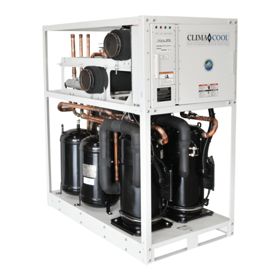
- Page 1 Remote Air Cooled Modular Chillers Model UCR: 30, 50, and 70 tons Installation, Operation & Maintenance Manual • •...
-
Page 2: Table Of Contents
Table of Contents Introduction . . . . . . . . . . . . . . . . . . . . . . . . . . . . . . . . . . . . . . . .1-2 Pre-Startup . -
Page 3: Introduction
Introduction General Description WARNING/ADVERTISSEMENT The ClimaCool Model UCR configurable remote air ® To avoid possible injury or death Pour éviter les blessures ou la mort cooled modular chiller is designed to provide the most due to electrical shock, open the par électrocution, ouvrir la interrupteur environmentally friendly, maneuverable, efficient, reliable power supply disconnect switch and... - Page 4 Introduction ATTENTION CAUTION/ATTENTION Never dispense liquid refrigerant into the suction port of a compressor while it Never attempt to vapor charge into Ne jamais essayer de vapeur frais is not running. If adding additional refrigerant is necessary, you must gradually the system high side, whether the dans le côté...
-
Page 5: Pre-Installation
Pre-Installation Inspection Upon receipt of equipment, carefully check the shipment against the bill of lading and inspect each chiller for any damage incurred during shipment . Thoroughly check for any visible damage of control panels and electrical and/ or refrigeration components or broken copper lines . The carrier must make proper notation of any damages or shortages on all copies of the bill of lading and complete a common carrier inspection report prior to final acceptance... -
Page 6: Model Key
Model Key www.climacoolcorp.com... -
Page 7: Physical Data
Physical Data Model UCR Module and Compressor Capacity (tons) 27.4 Refrigerant Circuits (quantity) Compressor Type Scroll Scroll Scroll Compressor Quantity Compressor Nominal hp (per circuit) Oil Factory Charge (per circuit) (oz.) Module Operating Weight w/Water (lbs.) 1265 1945 2085 Module Shipping Weight (lbs.) 1170 1785 1925... - Page 8 Remote Condenser Physical Data: 30°F TD & 110°F Maximum Ambient Remote Condenser “H” Series Model UCR Model RC (1140 RPM / 30°F TD / 110°F Max Ambient) RC1-008A*H20 RC2-026A*H48 RC2-031A*H48 Quantity of Remote Condensers Needed Heat Exchanger (Remote Air-Cooled Type) Alum.
- Page 9 Remote Condenser Physical Data: 20°F TD & 120°F Maximum Ambient Remote Condenser “H” Series Model UCR Model RC (1140 RPM / 20°F TD / 120°F Max Ambient) RC2-026A*H48 RC2-038A*H44 RC2-047A*H62 Quantity of Remote Condensers Needed Heat Exchanger (Remote Air-Cooled Type) Alum.
- Page 10 Variable Speed Remote Condenser Physical Data: 30°F TD & 110°F Maximum Ambient Remote Condenser “V” Series Model UCR Model RC (Variable Spd / 30°F TD / 110°F Max Amb.) RC2-020A*V48 RC2-025A*V42 RC2-033A*V42 Quantity of Remote Condensers Needed Heat Exchanger (Remote Air-Cooled Type) Alum.
-
Page 11: Dimensional Data And Piping Arrangement
Dimensional Data and Piping Arrangement Figure 1 - Dimensional Drawings Header Width Chilled Water Outlet Chilled Water Inlet Control Box Unit Width Right Side Front View View Table 1 - Dimensional Data Unit Dimensions (in inches) Header Unit Operating Model Unit Unit Header... -
Page 12: Rigging And Lifting Procedures
Rigging and Lifting Procedures Rigging Each module should be lifted by using lift straps threaded through the steel base cut outs and the use of a spreader bar . Note: If no spreader bar is used, damage to the unit may occur . Figure 3 Figure 4 Lifting Strap... -
Page 13: Mounting Rail And Vibration Isolation
Mounting Rail and Vibration Isolation ClimaCool recommends locking down the chiller to a concrete base or to three (3) 4” base mounting rails using the six (6) 4” Rail Minimum Recommended bolt holes provided in each base pan . Due to the low vibration of the modules, the application of spring isolators or pads is (by others) not required . -
Page 14: Recommended Service Clearances
Recommended Service Clearances Top View 30” 30” Rear Service Access 12” Front Service Access 36” 36” CoolLogic Control Panel (Wall Mounted) Notes: 1 . Allow 36” clearance for electrical panels and 30” clearance for rear access to modules . 2 . Allow a minimum of 18” height clearance for service . 3 . -
Page 15: Unit Installation
Unit Installation Unit Placement Field installing the mounting hardware kit will assist with alignment of the modules in a bank and eliminate offset ClimaCool modular chillers must be installed in a inconsistencies. The 1/2” mounting holes are provided on sides conditioned and dehumidified space. - Page 16 Unit Installation Inspect the pipe ends to ensure they are free from any CAUTION/ATTENTION indentations, projections, roll marks or other harmful 3 PHASE SCROLL UNITÉ COMPRESSEUR surface defects such as loose paint, scale, dirt, chips, COMPRESSOR UNIT SCROLL 3-PHASE grease and rust . Inspect the grooved coupling gasket for any defects .
-
Page 17: Electrical Connection
Electrical Connection Proper Voltage Balance The power for all modules is taken from a suitable circuit breaker/fused disconnect power supply within the main Occasionally, in three phase circuits, a voltage imbalance panel . The electrical service enters the individual modules occurs between phases . -
Page 18: Communications Wiring
Communications Wiring Avoiding Noise WARNING/ADVERTISSEMENT Avoid running communication wires or sensor input wires For field installation of Port 1 Pour l’installation sur place du next to AC power wires or the controller’s relay output communication wiring, installer must câblage de communication du port 1, wires. -
Page 19: Voltage/Phase Monitor Wiring Diagram
Voltage/Phase Monitor Wiring Diagram www.climacoolcorp.com... -
Page 20: Water Piping
Water Piping Water Isolation Valves As with any water system, it is important that the system be clean . If care is taken during installation, the possibility It is recommended to provide bank water isolation valves for of dirt related problems are avoided in future operation proper isolation and maintenance of the chiller, pump and of the chiller . - Page 21 Water Piping Load Side System Bypass Figure 10 - Direct Return (Air Handlers, Fan Coils, etc.) Hose Kit Hose Kit A load system bypass is required for preventing pump deadheading, allowing active flow system sensing and SIDE VIEW END VIEW preventing starving flow from the chiller system.
-
Page 22: Water Piping Configurations
Water Piping Configurations Figure 13 - Field Piping Direct Return Figure 14 - Field Piping Reverse Return Notes: Figures 13 and 14 are required piping for proper water regulation and distribution through ClimaCool modular chillers . Module order and incoming/outgoing water flow as shown in both Figure 13 and 14 can be set up as either a left-to-right or right-to-left configuration. -
Page 23: Hydronic Refrigeration
Hydronic Refrigeration Figure 15 - Chilled Water Circuit Refrigerant Circuit #1 Service Ports (3/4”) Refrigerant Circuit #2 Isolation Ball Valves Leaving Chilled Water (2 or 2-1/2”) Temperature Sensor Pete’s Ports Heat Exchanger Note: Figure 15 depicts hydronic piping in each ClimaCool chiller module and is shown with water isolation valves . www.climacoolcorp.com... -
Page 24: Part-Load Performance Advantage
Part-Load Performance Advantage Figure 16 Optimum Performance Every Time – Water In (Hot) Even at Part Load . Refrigerant Refrigerant Circuit 1 Circuit 2 Water Out (Cold) Refrigerant Circuit 2 Only If circuit 1 is cut, the unique ClimaCool modular chillers employ reliable and highly design allows each water efficient brazed plate heat exchangers. -
Page 25: Filling The Water System
Filling the Water System Cleaning the System It is imperative that the water systems are free from debris prior to initial operation (see Water Treatment for The following method is recommended to properly clean a comprehensive list of precautions on page 24) . the water systems: Before cleaning the system, install a temporary bypass Filling, Purging and Leak Testing the System... -
Page 26: Water Treatment
Water Treatment Water quality is of the utmost importance for the proper Table 3 - Water Quality Parameters care and maintenance of the modular chiller system. Proper Water Containing Concentration water treatment is a specialized industry and ClimaCool Ammonia Less than 2.0 mg/l recommends consulting an expert in this field to analyze CaCO Alkalinity... -
Page 27: Water Temperature Requirement
Water Temperature Requirement Chilled Water Temperature Modules are designed for a leaving water temperature range from 40°F to 62°F . All cataloged modules can operate safely in this range without the need of special controls or glycol additives . Leaving water temperatures below 40°F can result in evaporator suction temperatures below the freezing point of water . -
Page 28: Operating Limits
Operating Limits Voltage Limitations The following voltage limitations are absolute and operation beyond these limitations may cause serious damage to the compressor. Nominal Voltage Minimum Voltage Maximum Voltage 208/230/3/60 460/3/60 575/3/60 Water Flow Data UCR030 UCR050 UCR070 Minimum Evaporator Water Flow (gpm) Maximum Evaporator Water Flow (gpm) Minimum Leaving Evaporator Water Temperature (No Glycol)(°F) Minimum Leaving Evaporator Water Temperature (with Glycol)(°F) -
Page 29: Evaporator Water Pressure Drop Charts
Evaporator Water Pressure Drop Charts www.climacoolcorp.com... -
Page 30: Glycol Performance Adjustment Factor Charts
Glycol Performance Adjustments Factor Charts www.climacoolcorp.com... - Page 31 Glycol Performance Adjustments Factor Charts Table 4 - Performance Adjustment Factors vs. Altitude vs. Chiller Temperature Drop Chiller Sea Level 2000 ft. 4000 ft. 6000 ft. Water Flow Flow Flow Flow Capacity Capacity Capacity Capacity Temp. Power Power Power Power Multplier Multplier Multplier...
-
Page 32: Power Distribution Drawing
Power Distribution Drawing MAIN PD\./ER FEED Figure 17 208-230/460/575V 3PH 115V-1PH TYPICAL (6,0 AMpS MlnlMUM) MODULE PD\./ER FEED BREAKER PANEL --------------7 208-230/460/575V 3PH C□NTR□L PANEL • 1 1 � : •. ; . 1 1 1 �: ■ 0000 0000 0000 �l : 1 �... -
Page 33: Remote Condenser
Remote Condenser Space and Location Requirements Multiple Units The most important consideration which must be taken For units side by side, the minimum distance between units into account when deciding upon the location of air is the width of the largest unit . If units are placed end to cooled equipment is the provision for a supply of ambient end, the minimum distance between units is 4 feet . - Page 34 Remote Condenser Control Panels Table 6 - Ambient Fan Cycling Thermostat Settings Factory assembled fan cycling control panels are available Number of Fans Thermostat Setting Design to cycle fans for head pressure control either on ambient Temperature Single Double temperature or condensing pressure . Contact ClimaCool for Differential °F custom applications for fan speed control or customer built 30°...
-
Page 35: Head Pressure Control Valve Operation (Lac-10)
Head Pressure Control Valve Operation (LAC-10) High and Low Ambient Stability LAC-10 Valve Operation The design of air conditioning systems, utilizing air cooled The valve designation LAC stands for Low Ambient Control . condensing units, involves two main problems that must be The LAC-10 is a three-way modulating valve that responds solved if the system is to operate reliably and economically;... - Page 36 Head Pressure Control Valve Operation (LAC-10) Brazing Procedures for Head Pressure Length of tubing and return bends in condenser Control Valve Minimum ambient temperature at which systems will be Any of the commonly used brazing alloys for high side required to function usage are satisfactory, however, when soldering or brazing, Tubing size and wall thickness it is very important that the internal parts be protected...
- Page 37 Head Pressure Control Valve Operation (LAC-10) since as the compressor unloads, the condenser’s capacity increases and additional flooding is required. Using the same roof mounted remote condenser as in the earlier example (40°F evaporator and minus 20°F minimum ambient), a multiplier of .79 is shown in Table 8.
- Page 38 Head Pressure Control Valve Operation (LAC-10) Charging of Systems with Sporlan Head Pressure At this point the system is correctly charged for this type of head pressure control at the ambient temperature Control in Ambient ABOVE 70°F that exists while the charging procedure is taking place . (After normal evacuation procedures) If the system is designed to operate at ambient below Before starting system:...
- Page 39 Head Pressure Control Valve Operation (LAC-10) Malfunction – Low Head Pressure Chart Possible Cause Remedy Insufficient refrigerant charge to adequately flood condenser Add refrigerant LAC fails to close due to: See Below: a. Foreign material in valve a. Cause LAC to open by raising condensing/receiver pressure above b.
-
Page 40: Remote Condenser Installation
Remote Condenser and UCR Chiller Installation Diagram www.climacoolcorp.com... - Page 41 Condenser Layout for RC1-007A*H24 and RC1-008A*H24, 1-Row, 2-Fan, 1140RPM www.climacoolcorp.com...
- Page 42 Condenser Layout for RC2-019A, 026A and 31A*H48 and RC2-038A*H44, 2-Row, 4-Fan, 1140RPM www.climacoolcorp.com...
- Page 43 Condenser Layout for RC2-018A*X48, RC2-026A*X40 and RC2-032A*X44, 2-Row, 4-Fan, 830 RPM www.climacoolcorp.com...
- Page 44 Condenser Layout for RC2-014A*Q48, RC2-017A*Q42, RC2-021A*Q48 and RC2-025A*Q44, 2-Row, 4-Fan, 540 RPM www.climacoolcorp.com...
- Page 45 Condenser Layout for RC2-020A*V48, RC2-025A*V42, RC2-033A*V42 and RC2-038A*V42, 2-Row, 4-Fan, Variable Speed www.climacoolcorp.com...
- Page 46 Condenser Layout for RC2-047A*H62, RC2-046A*V60, RC2-032A*Q62, RC2- 039A*Q64, RC2-039A*X60 and RC2-047A*X62, 2-Row, 6-Fan www.climacoolcorp.com...
- Page 47 Condenser Layout for RC2-048A*Q82, 2-Row, 8-Fan, 540RPM www.climacoolcorp.com www.climacoolcorp.com...
-
Page 48: Pre-Startup
Pre-Startup Water System All startups must be performed by ClimaCool factory trained personnel. Prior to chiller startup, there are certain Confirm that leak testing has been carried out. essential checks which must be completed . Failure to carry Confirm that the system is clean. out these checks could result in damage to the chiller voiding the modules warranty . -
Page 49: Pre-Startup Checklist
Pre Start-Up Checklist* (Air-Cooled) UCR E-mail technicalsupport@climacoolcorp.com • Fax: 405.815.3000 Project Name: Date: Address/Phone: Are modules connected properly “per Codes and ClimaCool Installati on Manual and completed Remote Condenser Warranty Agreement/Acknowledgement”? (Installati on, Operati on & Maintenance (IOM) Manual is available at www.climacoolcorp.com). Is there a 60-80 mesh strainer on the evaporator inlet water? (Fill water to chiller being sure to pass through a minimum of 60 mesh strainer.) Is chilled water system fi... -
Page 50: Startup
Startup 10 . All startups must be performed by ClimaCool factory Confirm the jumper locations for all master controller trained personnel . and module controllers as shown on the wiring diagrams provided on the inside electrical door panels . Review all items are complete from the Pre-Startup Checklist . - Page 51 Startup 18 . Verify proper communications from each module back Verify proper superheat by subtracting the saturated to the master controller using the “STATUS” menu, evaporative temperature from the suction line temperature . then indexing down to the desired compressor data The saturated evaporative temperature is found by screen .
-
Page 52: Subcooling & Superheat Flow Chart
Subcooling & Superheat Flow Chart Compressor for 5 Minutes Is Superheat in Range? Is Superheat Is Subcooling Low or High? in Range? High Recheck Superheat Turn TXV Is Subcooling Is Subcooling and Complete Adjustment Low or High? Low or High? Start-up and Stem Clockwise Warranty Form... -
Page 53: Split System Startup
Split System Startup Step 4: Once installation is complete, check the following: After starting the compressor, listen for unusual sounds such as knocking . If heard, immediately stop the All refrigerant and electrical connections must be tight . • compressor . Do not restart until the problem is resolved . Tighten all loose wire terminal connections that may While scroll compressors are more tolerant to liquid have loosened in shipping . -
Page 54: Startup And Warranty Registration Form
Startup and Warranty Registration Form (Air Cooled UCR) Ambient Sign, date and E-mail to: technicalsupport@climacoolcorp.com or 1 of 1 Fax: 405.815.3000 Attn: Technical Support Temp: Page: Project Name: Contractor Name: Address: Address: City/State/Zip: City/State/Zip: Startup Date: Phone No: Module Compressor Model No.: Model No.: Serial No.:... -
Page 55: Remote Condenser Warranty Agreement
Remote Condenser Warranty Agreement E-mail technicalsupport@climacoolcorp.com • Fax: 405.815.3000 Project Name: Project Address: Installing Contractor Name (Print): Date: In the le� -hand margin, indicate you have verifi ed the accuracy of each line item by ini� aling each numbered item below. 1. -
Page 56: Remote Air Cooled Chiller Operation And Maintenance
Remote Air Cooled Chiller Operation and Maintenance Pressure and Temperature Log the bank performance sheet for the project for these values . If the temperature drop/rise is greater A log of temperatures and pressures should be taken than the design, the heat exchanger may need to be regularly . -
Page 57: Heat Exchangers
Heat Exchangers Draining to the normal operational direction . Connection points are provided using the 3/4” service ports at each heat exchanger. When performing standard maintenance procedures The cleaning solution used can be either a detergent or hot such as flushing a heat exchanger, it will be necessary to water to remove particles and simple cleaning . -
Page 58: Cleaning Arrangement
Connect to City Water To Cooling Tower Cleaning Arrangement Header Refrigerant Circuit Figure 1 - City Water Cleaning Arrangement Pete's Ports Figure 25 - City Water Cleaning Arrangement Isolation Ball Valves (2, 2 ½ or 3") Service Port (3/4") Header Connect to City Water Refrigerant Circuit From Cooling Tower... -
Page 59: Compressor Information
Compressor Information Model UCR uses scroll compressors which are highly ATTENTION efficient and extremely reliable. The information contained To avoid the release of refrigerant into the atmosphere, the refrigerant circuit of in this manual will be useful for their care . this unit must be serviced only by technicians who meet local, state and federal proficiency requirements. -
Page 60: Refrigeration Circuit Diagram
Refrigeration Circuit Diagram REMOTE AIR COOLED FACTORY CHILLER CONDENSER FIELD PIPING WATER PIPING CHILLER OUTLET WATER MAIN (6") CHILLER INLET CONDENSER WATER MAIN (6") AIR EXHAUST CHILLER WATER OUTLET CONDENSER FAN(S) CHILLER VALVE WATER INLET (WHEN USED) VALVE (WHEN USED) FLUSH SHUT‐OFF VALVE FILL SHUT‐OFF VALVE PETE'S PORTS LOCATE BULBS SO THEY SENSE OUTDOOR AIR CONDENSER EQUALIZER AIR INTAKE LINE TXV BULB COMPONENT LEGEND... -
Page 61: Refrigeration Systems Re-Processing
Refrigeration System Re-Processing Copper Tubing, Brazing and System Conforming to local and national codes is the responsibility of the service technician or installing contractor . The service Reprocessing Recommendations technician should be familiar with the following codes: Copper tubing must be refrigeration grade (ACR type •... -
Page 62: Split System Interconnecting Piping
Split System Interconnecting Piping Discharge Line Piping Recommendations condensing pressures. This will result in inefficient system operation and potentially cause nuisance head pressure All discharge lines should be kept as short as possible and trips . Moisture in the system can cause chemical reactions the line sizing is determined to provide for a low-pressure with many POE oil additives resulting in the formation of drop . -
Page 63: Refrigerant Charging Procedure
Refrigerant Charging Procedure Refrigerant Charging CAUTION/ATTENTION Once leak testing and evacuation are complete, refrigerant Never attempt to vapor charge into Ne jamais essayer de vapeur frais charging may commence . Always refer to the unit the system high side, whether the dans le côté... - Page 64 Refrigerant Charging Procedure Table 11 – UCR030 Additional Refrigerant Foot of Liquid Total Winter Minimum Condenser Model # Line (⅞” OD) Charge lbs Outdoor Temp. Fan RPM (External) R-410A 1140 74.8 +25F 1140 81.8 -20F 1140 88.8 1140 77.8 +25F 1140 84.9 -20F...
-
Page 65: Engineering Guide Specifications
Engineering Guide Specifications General Compressors Factory-assembled and wired remote air cooled chiller . Each module shall contain two scroll compressors Chiller consists of two compressors, one evaporator, safety independently circuited for redundancy . Each compressor and operational controls . The modular remote air cooled shall be mounted with rubber isolated compressor mounts chiller shall incorporate one or more modules with two to the module base and each shall include compressor... - Page 66 Engineering Guide Specifications CoolLogic Control System Remote CoolLogic Control system shall be fully compatible with the Building Automation System via native BACnet and LonWorks communication protocols . Scheduling of the various compressors shall be performed by the master microprocessor based controller . A compressor run time equalization sequence is provided to ensure even distribution of compressor run time .
-
Page 67: Options And Accessories
Options and Accessories Automatic CS Series Strainer Package Field installed, high quality, low maintenance stainless steel filtration systems with 60 or 80 mesh stainless steel screens will reduce operating costs and prevent nuisance condenser issues. Strainer package can be equipped with optional pressure differential alarm and automatic time flush. -
Page 68: Stainless Steel Strainer Option
Stainless Steel Strainer Option Strainer Installation Recommendations Figure 27 - Stainless Steel Strainer Follow the recommended guidelines below for the strainer installation: The carbon steel (CS) strainer should be placed on a firm, supporting surface. Failure to do so can cause stress on the weld joints . - Page 69 Stainless Steel Strainer Option Strainer Element Cleaning Table 13 If the strainer assembly is equipped with optional pressure Bolt Size Recommended Torque Strainer gauges, the operator will be able to monitor the pressure (inches) (ft. lbs.) differential between the inlet and outlet sides of the strainer. 3 CS 5/16 - 18 60 - 80...
- Page 70 Stainless Steel Strainer Option What is Water Hammer? Figure 29 Water hammer is a phenomenon that can occur in fluid RED POINTER systems with long pipes . Water hammer is a rapid change OUTER RING of pressure caused by a rapid change in velocity. If the flow (TIME BETWEEN has been abruptly shut off downstream, the pressure in the FLUSHES)
- Page 71 Stainless Steel Strainer Option Operation Instructions Water Resistance Flush valve line must be piped to atmospheric pressure such The valve and controller are water-resistant, but not as an open floor drain. The flush line should not undergo water-proof . Do not install below ground level where the any changes in elevation and should be sloped downward in component can be submerged in water .
- Page 72 Stainless Steel Strainer Option When the differential set point is reached, both the audible and visual alarms will be triggered and will remain engaged until both the alarm condition is corrected and the alarm- reset button is pressed . If the alarm-reset button is pressed but the differential pressure is beyond the set point, the alarms will re-engage immediately .
-
Page 73: Wye Strainers
WYE Strainers Pre Installation Checklist: Installation Procedure: Ensure working conditions (pressure/temperature) Also, for maximum efficiency, install a differential are within the specified capacity of the product being pressure gauge at inlet and outlet connections or at the installed. Please refer to the certified drawings to assist strainer gauge tap (if provided) . - Page 74 WYE Strainers Start-Up Procedure Screen Removal/Cleaning/Replacement To remove all fluid from the strainer belly, a drip-leg can Isolate the strainer by closing the inlet and outlet valve be installed or the piping can be placed at a 1/4” slope. connections on either side of the WYE strainer . Make Note: With piping systems that contain fluids other sure valves are bubble tight .
-
Page 75: Basket Strainers
Basket Strainers The correct size of Basket Strainer is determined by its job Install a standard ANSI (1/8” thick) flange gasket function, not by the size of the pipeline . between the basket strainer and pipeline flanges, on both sides. Install lubricated flange bolts and hand Pre Installation Checklist: tighten . - Page 76 Basket Strainers Maintenance Strainer Element Cleaning Basket strainers require little monitoring once they are Before removing the cover of the basket strainer, the properly installed. The pressure differential across the strainer pressure inside the vessel must be reduced to atmospheric should be checked periodically to determine if the screen via suction or venting .
-
Page 77: Electrical Data Ucr
Electrical Data UCR www.climacoolcorp.com... -
Page 78: Wiring Diagrams
Wiring Diagram www.climacoolcorp.com... - Page 79 Wiring Diagram www.climacoolcorp.com...
- Page 80 Wiring Diagram - CoolLogic Control Panel www.climacoolcorp.com...
- Page 81 Wiring Diagram - CoolLogic Control Panel www.climacoolcorp.com...
-
Page 82: Troubleshooting Guide
Troubleshooting Guide WARNING! Compressor Cycles On High Pressure Control The troubleshooting guidelines recommended in this Possible Cause Remedy Water regulating valve section could result in exposure to electrical safety hazards . Reset or replace. incorrectly set or defective Refer to the safety warnings provided in this manual . Failure Compressor discharge Open valve to full open position. -
Page 83: Warranty
Warranty www.climacoolcorp.com... - Page 84 15 S . Virginia Oklahoma City, OK 73106 Phone: 405 .815 .3000 Fax: 405 .815 .3052 • • www .climacoolcorp .com ClimaCool works continually to improve its products. As a result, the design and specifications of each product at the time for order may be changed without notice and may not be as described herein.
Need help?
Do you have a question about the CLIMACOOL UCR 30 and is the answer not in the manual?
Questions and answers