Advertisement
Quick Links
Advertisement

Related Manuals for Eddyfi Technologies MIZ-21C


Summary of Contents for Eddyfi Technologies MIZ-21C
- Page 1 Getting Started with MIZ 21C...
- Page 2 ©2024 Eddyfi Canada Inc. Eddyfi and their associated logos are trademarks or registered trademarks of Eddyfi Canada Inc. in Canada and/or other countries. Eddyfi Technologies reserves the right to change product offerings and specifications without notice. Eddyfi Technologies is a Previan Business Unit Eddyfi MIZ-21C User Manual www.eddyfi.com...
- Page 3 The MIZ-21C is designed to perform non-destructive inspections on industrial and commercial materials. Indoor or outdoor use when battery powered (protected at all times from liquids, dust, direct sunlight, precipitation, and wind). When using the MIZ-21C in a handheld operation, do not remove the protective cover.
- Page 4 Do not use MIZ-21C AC power adapter in wet areas to avoid electrical shock. In these conditions it is recommended to operate your instruments on battery power. www.eddyfi.com...
- Page 5 Operating Temperature Range while using the MIZ-21C. The Marking on the Batteries is LIION Wholesale Part#lgmj1pcb. When close to the maximum operating temperature, the MIZ-21C may turn off if using a very demanding setup like running rotating scanners. If that happens, then return the MIZ-21C to room temperature for an hour and the thermal protection will reset which will make the MIZ-21C functional again.
- Page 6 Due to its nature, this instrument may contain small quantities of substances known to be hazardous to the environment. For this reason, MIZ-21C and ZM-5 equipment should never be disposed of in the public waste stream.
- Page 7 Security Standards The MIZ-21C is a Class 1 instrument of installation category II. It complies with standard EN- 61010-1 (2010). MIZ-21C Warranty Any warranty covering this device is limited, conditional, and to the original buyer, only, strictly in accordance with the terms and conditions set forth in Eddyfi Technologies’s quotation.
- Page 8 Setting up Scanners and Encoders ................................ 16 MIZ-21C Battery Replacement ................................16 Battery Charging ....................................18 ZM-5 Rotating Scanner Kit ..................................19 Features ........................................ 20 Navigation and Controls ..................................22 Control Hints ......................................23 MIZ-21C General Data Display Layouts ......................24 www.eddyfi.com Eddyfi MIZ-21C User Manual...
- Page 9 Calibrating Data ....................................36 Software User Interface ..........................38 Technique Parameters ..................................38 Probe Information ....................................45 Filters ........................................48 MIZ-21C Tools Menu ..................................... 60 Working Examples............................67 Calibration Tutorial ..................................... 67 Manage Calibration ..................................... 75 Encoder Configuration ..................................77 Screenshots ......................................
- Page 10 Standard Eddy Current Connector ..............................142 Eddy Current Array Connector ................................143 Alarm Interface ....................................144 Digital Inputs ....................................... 144 USB Connector ....................................144 Power Connector ....................................145 11. Problem with Your MIZ-21C Instrument ..................... 146 Basic Troubleshooting ..................................146 www.eddyfi.com Eddyfi MIZ-21C User Manual...
- Page 11 The MIZ-21C is available in six models with varying features suited for multiple applications. Throughout this manual, references may be provided on features not included in your specific model. Compare the model information tag on the back of your MIZ-21C with the following table to understand your exact features.
- Page 12 Charging Port Direct Current The MIZ-21C shall only be connected to the supplied power adapter and cables for charging and/or operating. Use of an improper power adapter may result in loss of data or damage to the instrument. Charging the instrument while operating it in high ambient temperatures may reduce charging efficiency.
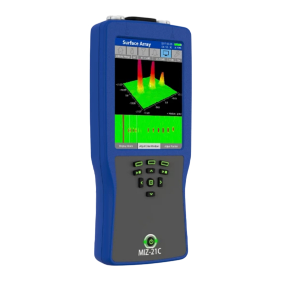
- Page 13 2. Preparing the MIZ-21C Positioning the MIZ-21C The MIZ-21C is a portable, handheld instrument with a touch display. It can be held with either hand. All buttons can be accessed using the thumb. It can also be positioned on a table or cart, or the floor.
- Page 14 The eddy current array connector accepts multiple coil eddy current array probes. The Wireless Locked models follow the same table of connecting probes for the SF, DF, and ARRAY versions. Figure 2-2 – MIZ-21C models and connecting probes www.eddyfi.com Eddyfi MIZ-21C User Manual...
- Page 15 The following shows the variety of probes that can connect to the MIZ-21C. You can refer to the probe catalog for more details and for part numbers: www.eddyfi.com/en/product/miz-21c Figure 2-3 Compatible probes www.eddyfi.com Eddyfi MIZ-21C User Manual...
- Page 16 Setting up Scanners and Encoders The MIZ-21C is compatible with a wide range of rotating scanners. Start by using the correct adapter to connect the rotating scanner. In the Bolt Hole technique, select the scanner that is connected to properly drive the scanner.
- Page 17 Ensure that the batteries are installed with the correct polarity direction as shown in the illustration. The MIZ-21C has polarity direction icons in the battery cavity as an indicator of the correct polarity direction for installed batteries.
- Page 18 10 hours of operation during typical use. Use of the MIZ-21C while charging batteries is permissible; however, simultaneous charging and operation of the MIZ-21C may cause the batteries to elevate beyond efficient charging levels depending on the test configuration being used and the environmental conditions. It is recommended to turn off the MIZ-21C to be sure the batteries fully recharge.
- Page 19 The ZM-5 uses a quick-disconnect cable design for easy replacement. The MIZ-21C can also adapt to other manufacturer’s rotating scanners using adapters. Figure 2-5 MIZ-21C and the ZM-5 High-Speed Scanner...
- Page 20 81 x 23 x 36 mm (3.2 x 0.9 x 1.4 in) Supported Instruments and Probes • Eddyfi Technologies MIZ-21C eddy current instrument using the 6-ft ZM-5 High Speed Rotating Scanner Control Cable • Rotating scanner probes with 4-pin Fischer connector from Eddyfi Technologies or other manufacturers www.eddyfi.com...
- Page 21 • Press the MIZ-21C Start/Stop button to rotate the probe and acquire data. • With the probe coils away from the hole edges, press the MIZ-21C Instrument Null button. The probe will stop rotating during the null process. It will begin rotating again after nulling.
- Page 22 Several user-control buttons which provide an alternative to on-screen software buttons for many functions are incorporated into the front panel of the MIZ-21C. This is useful when the job requires the use of gloves that may not be compatible with using the touch enabled display screen.
- Page 23 Figure 2-8 Navigation screen Control Hints The MIZ-21C is designed to be intuitive and simple to operate. Throughout the application, Control Hints on the status bar show you how to use the current feature. Figure 2-9 Control hints www.eddyfi.com...
- Page 24 3. MIZ-21C General Data Display Layouts Display modes are set according to the Application Type in use. The MIZ-21C produces both Impedance and C-scan data screens. The content of the screen is automatically adjusted depending on the current mode to provide you with the most relevant controls for operation.
- Page 25 When edits have been applied to the saved technique, an asterisk appears next to the name to indicate it has been modified. This area is also used to show operational hints, when available. www.eddyfi.com Eddyfi MIZ-21C User Manual...
- Page 26 Display shows the context menu to adjust modes of display, cursor position, and position of displayed data onscreen. Tools displays context menus to save the data file, make measurements of signals, and access the tools menu. www.eddyfi.com Eddyfi MIZ-21C User Manual...
- Page 27 Select the on-screen menu to enable the settings menu for the eddy current Drive voltage. Changes to the Drive voltage value will be applied the next time the acquisition is started with the Start/Stop Acquire button. Drive is a function of the technique. www.eddyfi.com Eddyfi MIZ-21C User Manual...
- Page 28 Select by function button directly menu item on the below the screen option. screen. Data Display Area Impedance Display C-Scan Data 3D C-Scan Data Lissajous data Data display 2D C-Scan Data Strip Chart Data Data buffer www.eddyfi.com Eddyfi MIZ-21C User Manual...
- Page 29 In the C-scan Display, the cursor is represented by the arrow in the 3D data, which corresponds with the intersection of the dotted lines in the Data Window of the 2D data. www.eddyfi.com Eddyfi MIZ-21C User Manual...
- Page 30 Getting Started Read the safety precautions before your first use to ensure safe operation. The following information provides steps for quick start operation of the MIZ-21C. Powering Up the Instrument With batteries at full charge, press the power button on the front panel to power up the MIZ-21C.
- Page 31 Selecting a Technique The Technique screen will display a list of techniques currently available on the MIZ-21C. When the Technique is highlighted Technique parameters are set correctly for the application, start acquisition using the Start/Stop Acquire button. View and edit the technique by selecting the technique on the screen or by using the right arrow on the keypad.
- Page 32 Start/Stop Acquire to initiate acquisition and start scanning the specimen. While acquiring, use the Context Menu button to perform Display Null, Instrument Null, and Clear the data buffer. Figure 3-6 Acquiring data www.eddyfi.com Eddyfi MIZ-21C User Manual...
- Page 33 Changing the Display The MIZ-21C offers a variety of display options that can be viewed during acquisition. You can cycle through these display options using the Left/Right control buttons while in acquire mode. When in Review mode, go to the Display tab and press Display mode repeatedly to cycle through the displays.
- Page 34 Independent mode. Holding down the center Select button will toggle between Independent and Uniform scale modes. Data Double tap on the Data Click center Window Buffer control button Zoom www.eddyfi.com Eddyfi MIZ-21C User Manual...
- Page 35 Data Window size Adjust Data Cursor Single tap and drag In any Screen mode that on the 2D display has Adjust Cursor available, select Adjust Cursor, then use the directional buttons to adjust position. www.eddyfi.com Eddyfi MIZ-21C User Manual...
- Page 36 See the Calibration Tutorial in the Working Examples section for more information on performing data calibration. Note: The MIZ-21C allows data to be calibrated offline in Review mode. Flaws used for calibration can be scanned once, and then the data can be calibrated in Review mode. There is no need to calibrate the data while repeatedly scanning over a flaw.
- Page 37 To reliably perform even a basic data analysis (such as evaluating the signal phase), • data must be analyzed offline. The operator can easily review different channels of data, make phase and amplitude measurements, and adjust other parameters to better characterize signals of interest. www.eddyfi.com Eddyfi MIZ-21C User Manual...
- Page 38 Conductivity and Coating Thickness has two selections: • o Eddyfi Technologies Conductivity Probe – Use this only if a Eddyfi Technologies Conductivity probe is being used. The MIZ-21C has been specifically calibrated with Eddyfi Technologies conductivity probes to ensure accurate measurements.
- Page 39 The type of Drive mode used is dependent on the probe’s coil configuration. The available Drive modes are listed below. Only the applicable Drive modes will be available depending on the Application selected. Absolute – Single coil. Also referred to as Absolute Bridge. The MIZ-21C’s virtual • reference completes the bridge circuit.
- Page 40 Sample Rate: This sets the data density (samples/unit of length) or data rate (samples/second) depending on the encoder setting. If encoder sampling is turned ON, the desired data density is set in terms of samples/unit of www.eddyfi.com Eddyfi MIZ-21C User Manual...
- Page 41 (same as independent per coil), but the signal used to set scale needs only to be seen by the channel being used for calibration. An example of this method is using the liftoff signal, which is seen by all coils to set phase, and then using www.eddyfi.com Eddyfi MIZ-21C User Manual...
- Page 42 Since this is vertical height, it is important that the phase has already been calibrated. • Do not use auto scale on a signal which is nearly horizontal as it will expand the • signal vertically. www.eddyfi.com Eddyfi MIZ-21C User Manual...
- Page 43 Double tap on the 3D C-scan brings up the C-scan shading menu Acquisition Displays: The MIZ-21C provides many display options while acquiring data. There are different display options for different applications. These displays can be enabled or disabled for the current technique.
- Page 44 Alarm – The alarm type that is applied to this channel. (See Software User Interface -> • Alarms for a more information on the types of alarms available.) www.eddyfi.com Eddyfi MIZ-21C User Manual...
- Page 45 Select from the available options. Part Number – Defines the type of probe being used. Encoder Type – Defines the type of encoder being used. Encoder Polarity – Defines the orientation of the encoder. www.eddyfi.com Eddyfi MIZ-21C User Manual...
- Page 46 If the encoder’s USB connector is on the same side as the USB connector of the Electronics Module, the polarity is normal. If it is on the opposite side, the polarity is reversed. www.eddyfi.com Eddyfi MIZ-21C User Manual...
- Page 47 To delete the underlay signal, select Clear Underlay. To remove it from the display, toggle the Underlay Enabled button to disable it. The underlay signal can be re-enabled at any time, but once it is cleared, it must be recaptured. www.eddyfi.com Eddyfi MIZ-21C User Manual...
- Page 48 Adjust Filter Context menu button. Figure 4-3 The following are brief descriptions of the various filters that are available on the MIZ-21C. Median Filter: The median filter removes background drift from the eddy current signal. Here are some examples of how the median filter can be useful: •...
- Page 49 Highpass-1 filter. In general, the median filter is a better filter to use than the Highpass-1 when hand scanning. • Typically, the absolute maximum cutoff value is established by increasing the cutoff value to a point where the reduction of the signal of interest begins. www.eddyfi.com Eddyfi MIZ-21C User Manual...
- Page 50 • Typically, the absolute minimum cutoff value is established by reducing the cutoff value to a point where the reduction of the signal of interest begins. www.eddyfi.com Eddyfi MIZ-21C User Manual...
- Page 51 User Parameters: • Low Cutoff: Signals below this frequency will be reduced. This is like the Highpass-1 filter cutoff. • High Cutoff: Signals Above this frequency will be reduced. This is like the Lowpass filter cutoff. www.eddyfi.com Eddyfi MIZ-21C User Manual...
- Page 52 Scaled Voltage, 1 volt = 1 division. Notes: • Since the threshold is the vertical limit, any change to the channel’s rotation or gain will affect which signals get filtered, therefore, the SNR filter should only be applied after signal calibration. www.eddyfi.com Eddyfi MIZ-21C User Manual...
- Page 53 For a differential type signal, the output signal of this filter will appear as a reverse figure 6 with a higher amplitude. Figure 4-5 Figure 4-6 Bolt hole data without HP2 applied Bolt hole data with HP2applied www.eddyfi.com Eddyfi MIZ-21C User Manual...
- Page 54 Please refer to the example graphics below. Figure 4-8 HP2 set too Figure 4-9 HP2 set too Figure 4-10 Optimal HP2 low – Significant signal high – Signal artifacts being setting – Maximum attenuati generated amplitude and straight signal applied www.eddyfi.com Eddyfi MIZ-21C User Manual...
- Page 55 Inner Mag to Zero. This type of alarm is useful when working with eddy current signals that have both a positive and a negative component allowing for the alarm to trigger on either side of the signal. www.eddyfi.com Eddyfi MIZ-21C User Manual...
- Page 56 There is also a visual cue when the alarm is triggered. The channel that is alarming will be highlighted in red and a red boundary will appear in the display. Figure 4-13 Visual alarm cue www.eddyfi.com Eddyfi MIZ-21C User Manual...
- Page 57 Change if alarm triggers when signal Right context button is inside or outside the alarm area Turn alarm on Right context button These controls can also be set in the technique for each channel. www.eddyfi.com Eddyfi MIZ-21C User Manual...
- Page 58 Single tap and drag Select the Adjust Position context menu from inside the alarm button. Use the Up/Down control area. buttons to adjust the radial position. Use the Right/ Left control buttons to rotate the phase window. www.eddyfi.com Eddyfi MIZ-21C User Manual...
- Page 59 Tools menu. There is also a visual cue when the alarm is triggered. The channel that is alarming will be highlighted in red and a red boundary will appear in the display. Figure 4-15 Visual cues www.eddyfi.com Eddyfi MIZ-21C User Manual...
- Page 60 MIZ-21C Tools Menu The Tools Menu provides a collection of tools and options to operate the MIZ-21C. Some options are specific to application types. Below is a brief description of the Tools Menu features. System Language The MIZ-21C offers several user language choices and can be set under this menu item.
- Page 61 0 - ±180 degrees scale. The default is the ASME method. The following pictures illustrate the different modes. Note the measured angle measurement in the orange circle in each picture. ASME ASME Inverted www.eddyfi.com Eddyfi MIZ-21C User Manual...
- Page 62 Data Persistence (For Applications Not Using a C-scan) Sets the time duration of the Data Window or the amount of data that will be displayed in the Data Display screen. Setting this to Manual Clear will effectively turn the Persistence off. www.eddyfi.com Eddyfi MIZ-21C User Manual...
- Page 63 Holding down the Clear button while acquiring data will also bring up this persistence screen: Figure 4-16 Lissajous persistence www.eddyfi.com Eddyfi MIZ-21C User Manual...
- Page 64 Sets the circumferential units of measure for a rotating scan. The options are Degrees or Clock. Write To Sets the location where the data will be saved, either to the internal drive storage or to an externally attached USB drive. www.eddyfi.com Eddyfi MIZ-21C User Manual...
- Page 65 Options to configure Network, Bluetooth, and Remote Displays. Hardware Diagnostics The MIZ-21C has built-in hardware diagnostics to test system performance. Diagnostics performs checks of many features without the need for external equipment. The Diagnostics (18 & 26-Pin) and Surface Array (Probe) diagnostics require the addition of a hardware load plug or a surface array probe, which places an impedance load on the system to test a greater portion of the system.
- Page 66 Status and Information This option provides a report of current version numbers of the operating system, software, firmware, and FPGA program for the MIZ-21C. The current runtime of the system and temperatures of critical components are also displayed. Display Dimming Timeout Sets the time duration the display is required to be idle before it goes to sleep.
- Page 67 Alternately, use the Auto Rotate Liftoff button to rotate the signal to the value set in the Technique options. Normally, this would be set to Horizontal, and the liftoff signal would be used to set the rotation. www.eddyfi.com Eddyfi MIZ-21C User Manual...
- Page 68 Alternately, use the Auto Scale Defect button to automatically adjust the scale to the value set in the Technique options. Place the signal to be scaled inside the data window and select the Auto Scale Defect context menu button. www.eddyfi.com Eddyfi MIZ-21C User Manual...
- Page 69 Horizontal and the liftoff signal would be used to set the rotation. In live mode, the desired signal must be captured within 3 seconds to use for rotation. The operation can be cancelled within 3 seconds. www.eddyfi.com Eddyfi MIZ-21C User Manual...
- Page 70 Technique options. In live mode, the desired signal must be captured within 3 seconds to use for rotation. The operation can be cancelled within 3 seconds. www.eddyfi.com Eddyfi MIZ-21C User Manual...
- Page 71 (Note: Manual adjustments will apply to all the channels at the same time. Therefore, Auto Rotate should be used initially to set the rotation of all channels to the same value.) After Rotation Figure 5-1 Before and after rotation www.eddyfi.com Eddyfi MIZ-21C User Manual...
- Page 72 Select button. The scale can also be locked to a 1:1 ratio by selecting this in technique options. After Scale Figure 5-2 Before and after scale www.eddyfi.com Eddyfi MIZ-21C User Manual...
- Page 73 In live mode, the desired signal must be captured within 3 seconds to use for rotation. The operation can be cancelled within 3 seconds. Figure 5-3 Live mode – data array www.eddyfi.com Eddyfi MIZ-21C User Manual...
- Page 74 3 seconds. Figure 5-4 Auto scale defect Note: If there are multiple channels, the calibration must be performed on each channel. Note: Whenever calibration is performed, the rotation should always be adjusted before adjusting scale. www.eddyfi.com Eddyfi MIZ-21C User Manual...
- Page 75 Default Setup. This will overwrite the existing Default Setup. When a new Setup is saved to the Technique, it will get an asterisk identifying that it has been modified. Then save the current Technique or rename it to something different. www.eddyfi.com Eddyfi MIZ-21C User Manual...
- Page 76 Note: Only one Review Setup can be saved per technique. Therefore, if there are several data files from the same technique, there will be only one Review Setup for all those data files. www.eddyfi.com Eddyfi MIZ-21C User Manual...
- Page 77 In this picture, the Encoder Type is set to Surf-X Flex. Press the Edit button to change the information in the Probe Information tab. Select the Encoder Type to change the encoder being used. Then select Custom on the following screen. www.eddyfi.com Eddyfi MIZ-21C User Manual...
- Page 78 When Calculator is selected, the wheel diameter and the encoder Counts Per Revolution can be entered. The encoder counts per revolution often is found on the encoder datasheet. From this information, the instrument will calculate the encoder resolution. www.eddyfi.com Eddyfi MIZ-21C User Manual...
- Page 79 When Live Calibration is selected, the encoder resolution is calculated by move the encoder over a known distance. Place the encoder at a start position and press Select Start Move the encoder over a known distance and press Select End. www.eddyfi.com Eddyfi MIZ-21C User Manual...
- Page 80 Enter the known distance on the next screen. From this information, the instrument will calculate the encoder resolution. www.eddyfi.com Eddyfi MIZ-21C User Manual...
- Page 81 Select the Close Viewer button to go back to the list of screenshots in the file manager. Use standard finger gestures to zoom and move the screenshot. www.eddyfi.com Eddyfi MIZ-21C User Manual...
- Page 82 It may be necessary to save just a portion of the data. When the strip chart or 2D C-Scan data is zoomed, only that portion of the data is saved. The data inside the Data Window can be zoomed by pressing the center select button. www.eddyfi.com Eddyfi MIZ-21C User Manual...
- Page 83 Select the Up One Level button to navigate to the Surface Array directory where a list of techniques in the application will be displayed. Select the left arrow to go back to the File Management menu. www.eddyfi.com Eddyfi MIZ-21C User Manual...
- Page 84 To save portions of a data file, zoom in on a particular area and use the Save File function. A new data file with only the zoomed in portion of the data will be created. Save a segment of a data file saving zoomed portion www.eddyfi.com Eddyfi MIZ-21C User Manual...
- Page 85 Make Live will extract this technique from the data file and will display this in the technique directory. This is useful if acquiring data using the exact same settings of how the data file was originally recorded. www.eddyfi.com Eddyfi MIZ-21C User Manual...
- Page 86 USB device is connected, the Copy to USB context menu button will be available in the lower left corner of the screen. In this way, individual files or whole folders can be saved to the USB device. www.eddyfi.com Eddyfi MIZ-21C User Manual...
- Page 87 Length measurements are displayed in either inches, centimeters, or millimeters. This can be selected in the Tools menu. There is an option that defines when to display measurements. Measurements can always be displayed, or only when making measurements. This option can be found in the Tools menu. www.eddyfi.com Eddyfi MIZ-21C User Manual...
- Page 88 2D C-scan display to move the cursor. Alternatively, with no context buttons selected, the cursor can be moved with the arrow buttons. The amplitude and phase measurements, as well as the cursor distance, are displayed under the impedance display. www.eddyfi.com Eddyfi MIZ-21C User Manual...
- Page 89 The normal impedance display only shows the data from one channel (or coil) that the cursor is on, and the measurement is taken on this signal. www.eddyfi.com Eddyfi MIZ-21C User Manual...
- Page 90 3D C-scan display. This is the C-scan Shading menu interface when accessed through the technique options. Changes to the settings will be displayed on the color palette on the right side of the display. www.eddyfi.com Eddyfi MIZ-21C User Manual...
- Page 91 Normal – Displays the data with positive amplitudes above the neutral plane and negative amplitudes below the neutral plane. Absolute – Applies the positive end color palette to both the positive and negative amplitude data. Positive Only – Removes all the negative amplitude data from the display. www.eddyfi.com Eddyfi MIZ-21C User Manual...
- Page 92 Each section corresponds to the start or end of the color transition and these transition points are denoted by the Threshold value. In this example, the Inner Threshold value is 1 division, and the Outer Threshold value is 2.0 divisions above null. www.eddyfi.com Eddyfi MIZ-21C User Manual...
- Page 93 To change the color, select the section to be modified, then select the color to use. The shades of the color can be adjusted using the two context menu buttons labeled Darken and Lighten. The range goes from 0 (darkest) to 10 (lightest). Here are some examples of custom color palettes: www.eddyfi.com Eddyfi MIZ-21C User Manual...
- Page 94 Note: The negative sections of the palette will be n/a if the Display Mode is set to Absolute or Positive Only. www.eddyfi.com Eddyfi MIZ-21C User Manual...
- Page 95 Make sure the primary inspection frequency is on Ch 1 and the suppression channel is on Ch 2. Figure 5-6 Mix channels Turning on the mix activates a third channel used for the mix www.eddyfi.com Eddyfi MIZ-21C User Manual...
- Page 96 Select Suppress Signal. If the result of the mix is satisfactory, select Done. If the mix is not satisfactory, clear the mix and try again with a different part of the signal. www.eddyfi.com Eddyfi MIZ-21C User Manual...
- Page 97 The result should be the suppression of unwanted signals with the desired flaw indications clearly visible. Mix channel 1 Resultant mix Mix channel 2 Figure 5-7 Frequency mixes www.eddyfi.com Eddyfi MIZ-21C User Manual...
- Page 98 26-pin requires a load plug that connects to each of the probe connectors and is performed at a Eddyfi Technologies Calibration Lab. Surface Array (Probe) requires an Array Probe to be connected to the 26-pin connector and can be performed by the user. The following table lists the checks each type of diagnostics performs.
- Page 99 Once all tests are complete, see a detailed report by selecting the View Report button. If a USB storage device is connected, there is also an option to copy the report to the storage device. www.eddyfi.com Eddyfi MIZ-21C User Manual...
- Page 100 Choose a range that is appropriate for the probe you are using. To create a plot, follow these steps: 1. Start acquire. 2. Balance the probe on the test material. 3. Scan a large defect. 4. Stop acquire. www.eddyfi.com Eddyfi MIZ-21C User Manual...
- Page 101 In this case, the Auto Scale can be turned off by selecting the Auto Scale On context menu button. The Up/Down arrows can be used to manually scale the data. www.eddyfi.com Eddyfi MIZ-21C User Manual...
- Page 102 Press the center control button to zoom in on the strip chart data. Figure 5-10 Selecting Done will exit out of the Swept Frequency feature. Once done, the data will no longer be available. www.eddyfi.com Eddyfi MIZ-21C User Manual...
- Page 103 Highlight the folder or file and select the Copy To USB context menu • button to copy to the USB device. Select the left arrow to return to the File Management screen. • www.eddyfi.com Eddyfi MIZ-21C User Manual...
- Page 104 Figure 5-12 File Management Options Figure 5-13 Individual files Individual files can be opened or copied to USB when highlighted. www.eddyfi.com Eddyfi MIZ-21C User Manual...
- Page 105 Technique Manager – Technique files can either be backed up to, or imported from, the USB device. Figure 5-15 Technique Manager When techniques are backed up or imported, only new techniques or newer revisions of existing techniques will be copied. Identical techniques will be ignored. www.eddyfi.com Eddyfi MIZ-21C User Manual...
- Page 106 The files on the USB device are organized in a similar file structure as on the instrument. The root directory will have a folder labeled “MIZ-21C”, which will contain a folder for Techniques and Screenshots (labeled “Pictures”) as well as logs, diagnostics reports, and software updates.
- Page 107 There is an option for a 'Best Fit' of points to the curve type, as well as an option for 'Continuous', where the curve is made up of any number of curves, smoothly interpolated together between calibration points. ‘Best Fit’ does not have to go through the points, while www.eddyfi.com Eddyfi MIZ-21C User Manual...
- Page 108 '0' in the keypad rather than trying to find a suitably quiet reading. Channels can be toggled during calibration, such that the cursor can be put on a desired flaw and then go www.eddyfi.com Eddyfi MIZ-21C User Manual...
- Page 109 Measurement Display should be selected to Always so that the measurement will always be displayed. If this is not selected, then it will only be displayed when making measurements. www.eddyfi.com Eddyfi MIZ-21C User Manual...
- Page 110 There are two sets of curves based on Volts or Angle. Each set has three options for curve types. The first is a Eddyfi Technologies proprietary depth curve algorithm, then Quadratic, and Linear. Notice that the button at the lower left of the display shows Continuous/Best Fit. This is because each curve type has two different ways to establish the curve.
- Page 111 0 reference point, that the user enter 0.00 volts at this point. This will hard set the curve so that 0 volts equals 0 percent. Once the first point is set, pressing the Right arrow will move the cursor to the next calibration point. www.eddyfi.com Eddyfi MIZ-21C User Manual...
- Page 112 (suggested for array data) or via the Tools, Measurement screen. However, once a depth curve has been established, depth measurements will automatically be displayed in the acquisition screen while the instrument is in Review mode. www.eddyfi.com Eddyfi MIZ-21C User Manual...
- Page 113 Note: It may be preferable to perform the calibration of the liftoff signal without the Highpass-1 and Highpass-2 filters enabled. If so, turn off the filters by going to the Filters tab and selecting the Adjust Filters button. www.eddyfi.com Eddyfi MIZ-21C User Manual...
- Page 114 Controls to enter adjust scale mode 11. Verify you are in Uniform scaling, then use the arrow keys to adjust the Gain so the liftoff signal is approximately full screen width 12. Press Done to exit adjust scale mode www.eddyfi.com Eddyfi MIZ-21C User Manual...
- Page 115 9. Press Done to exit out of adjust scale mode. At this point, the calibration is complete. It may be necessary to fine tune other settings. www.eddyfi.com Eddyfi MIZ-21C User Manual...
- Page 116 Note: The setup and technique do not need to be saved to continue. All settings are stored in non- volatile memory, even if the instrument is powered down. Saving the setup and technique allows the user to go back to these settings after other changes are made. www.eddyfi.com Eddyfi MIZ-21C User Manual...
- Page 117 4. Press the Start/Stop Acquire button to start acquisition 5. With the probe in air, press the Instrument Null button 6. Scan the bolt hole 7. Press the Start/Stop Acquire button to stop acquisition 8. Display channel 2 www.eddyfi.com Eddyfi MIZ-21C User Manual...
- Page 118 C-Scan Manipulation The graphic on the right shows what the bolt hole looks like when all settings factory defaults (channel rotations = 0°, H/V gains = 40 dB) and without any filters enabled. www.eddyfi.com Eddyfi MIZ-21C User Manual...
- Page 119 In most cases, the Inner and Outer Thresholds are the primary adjustments followed by the other C-scan Shading options. The following graphics illustrate how changing various C-scan shading parameters affect the display: www.eddyfi.com Eddyfi MIZ-21C User Manual...
- Page 120 Adjusting the Palette and Display Mode The above examples are just a few of the shading options available. Become familiar with all the options and how they affect the data to gain proficiency in optimizing the display. www.eddyfi.com Eddyfi MIZ-21C User Manual...
- Page 121 1. From the Applications page, select Conductivity and Coating Thickness 2. Select the Template – Conductivity technique 3. This technique uses the Eddyfi Technologies conductivity probe at the optimal 60 kHz for a test frequency. If a different frequency and/or probe is needed, press Edit to change the frequency and probe type.
- Page 122 30.00 %IACS and 60.00 %IACS will yield more accurate results than having a window between 3.00 %IACS and 100.00 %IACS. Note: The target conductivity and/or thickness values should be within the calibration points for best results. www.eddyfi.com Eddyfi MIZ-21C User Manual...
- Page 123 Press the Start/Stop button at any time to review all data stored in the buffer. In review mode, a time-based strip chart is displayed to make it easy to select measurements of interest. Figure 6-3 Positioning the curser at different conductivity data points www.eddyfi.com Eddyfi MIZ-21C User Manual...
- Page 124 3. This technique uses 2 kHz for a test frequency. If a different frequency is needed, press Edit and scroll to the bottom of the technique page to change the frequency. All other settings are appropriate for this general procedure. www.eddyfi.com Eddyfi MIZ-21C User Manual...
- Page 125 There is adequate separation between • the acceptable fasteners and notch “B” The notch signals are at least three • vertical divisions. 16. Press Done to exit Adjust Scale mode www.eddyfi.com Eddyfi MIZ-21C User Manual...
- Page 126 Since this technique is a template, it cannot be modified. Therefore, the technique needs to be given a new name. 4. Press the Edit button 5. Give the technique a new name 6. Press the Save button www.eddyfi.com Eddyfi MIZ-21C User Manual...
- Page 127 12. Adjust the data window so that only the groove signal is displayed: a. Touch: Use a pinch gesture to open or close the data window b. Buttons: i. Press Adjust Curser two times. The button label will change to Adjust Data www.eddyfi.com Eddyfi MIZ-21C User Manual...
- Page 128 Window. ii. Use the arrow keys to open or close the data window The following graphic shows how the data window should be positioned: Figure 6-5 13. Press Auto Rotate Liftoff www.eddyfi.com Eddyfi MIZ-21C User Manual...
- Page 129 The displayed signal will be scaled to 5 divisions. This is the default setting in the Auto Scale Defect Height field in the Technique settings. All other channels will have their scale set relative to the display channel since the Auto Rotate/Scale Mode is set to Single Scale. www.eddyfi.com Eddyfi MIZ-21C User Manual...
- Page 130 It may be useful to view a channel on the impedance plane when manually adjusting the rotation and scale: 2. Go to the Display tab 3. Press Display Mode until you have the tri-display of impedance, 3D and 2D C-scans as shown below: www.eddyfi.com Eddyfi MIZ-21C User Manual...
- Page 131 • Median Filter: The Filter Length should be set as low as possible, but at least two times the expected flaw length • SNR Filter: The vertical peak of the flaw signal should be significantly higher than the SNR limit www.eddyfi.com Eddyfi MIZ-21C User Manual...
- Page 132 3. Go to the Home tab. The Template – Bolt Hole 1 Freq technique is displayed with an asterisk indicating the technique has been modified. Since this technique is a template, it cannot be modified. Therefore, the technique needs to be given a new www.eddyfi.com Eddyfi MIZ-21C User Manual...
- Page 133 4. Press the Edit button 5. Give the technique a new name 6. Press the Save button www.eddyfi.com Eddyfi MIZ-21C User Manual...
- Page 134 8. Use the cursor to locate the liftoff signal 9. Press Adjust Rotation or touch the channel rotation value to enter adjust rotation mode 10. Use the arrow keys to rotate the liftoff signal horizontal www.eddyfi.com Eddyfi MIZ-21C User Manual...
- Page 135 The picture below is an example how the signals should look. Note: Use the Select button as needed to switch between Uniform and Independent scale modes www.eddyfi.com Eddyfi MIZ-21C User Manual...
- Page 136 3. Set the Median Filter Length to 3 Hz. Note: At 3 Hz, axial flaws longer than 150 data points will start having their signal amplitude reduced. Figure 6-12 Median filter applied to minimize signal drift www.eddyfi.com Eddyfi MIZ-21C User Manual...
- Page 137 4. Give the technique a new name 5. Press the Save button 7. Additional Learning Eddyfi Technologies offers training videos to supplement the information in this manual to help users become proficient with the setup and use of the MIZ-21C. Visit http://www.Eddyfi Technologies.com/miz-21c-training/...
- Page 138 8. Specifications General This section contains the general specifications for the MIZ-21C. Feature Specification Voltage 100 to 240 VAC, Auto-Switching Frequency 50 to 60 Hz Output Voltage 15 VDC Maximum Power 40 W Operating Temperature -10°C to 50°C (14°F to 122°F) Storage Temperature -20°C to 70°C (-4°F to 158°F) (w/out batteries)
- Page 139 Operating Specifications This section details the operating specifications of the MIZ-21C. Feature Specification Size (H × W × D) 267 × 122 × 38 mm (10.5 × 4.8 × 1.5 in) Weight 1.2 kg (2.6 lb) (including batteries and cover) Multi-Touch Display 5.7 in (480 x 640 pixels)
- Page 140 9. Maintenance Cleaning the Instrument The MIZ-21C external surfaces (housing and front panel) can be cleaned when needed. To clean the instrument: 1. Make sure the instrument is turned OFF, the power cord is disconnected, and all batteries are removed.
- Page 141 • Digital I/O tests • Factory Maintenance The MIZ-21C can be sent to one of Eddyfi Technologies’ service centers. These sites also perform calibrations. Licensing Your MIZ-21C software does not require licensing. Software updates can be found on the Eddyfi Technologies website and installed through the USB port.
- Page 142 BALANCE Balance, Digital Input: 3.3V to 5.0V MIZ-ID MIZ-iD Automatic Device Detection TACH* Tachometer ON-OFF* On/Off Momentary Switch HOLD Hold, Digital Input: 3.3V to 5.0V +3.3V +3.3 Volts @ 100 mA *Varies by Rotating Scanner www.eddyfi.com Eddyfi MIZ-21C User Manual...
- Page 143 Encoder 2B, Digital Input: 3.3V to 5.0V ENC2A Encoder 2A, Digital Input: 3.3V to 5.0V +3.3V +3.3 Volts @ 100 mA, Encoder Power Eddy Current Array MIZ-ID MIZ-iD Automatic Device Detection PRESET Encoder Preset, Digital Input: 3.3V to 5.0V www.eddyfi.com Eddyfi MIZ-21C User Manual...
- Page 144 The USB port also supports the connection of a USB hub so several peripherals can be connected at once. Charging Port USB 2.0 Description USB 2.0 Port, Type A, Female Connector Max. Cable Length Maximum Capacity Per Port 0.1 A www.eddyfi.com Eddyfi MIZ-21C User Manual...
- Page 145 Power Connector The charging port is used to attach the power adapter supplied with the MIZ-21C. The charging port is used to recharge the internal batteries. irect Charging Port urrent The MIZ-21C shall only be connected to the supplied power adapter and cables for charging and/or operating.
- Page 146 The table below lists the error messages a user may encounter. For each error message, a description of the message is given, followed by troubleshooting steps. If the problem is not resolved after performing the troubleshooting steps, contact Eddyfi Technologies for support. Error Message...
- Page 147 Load a different data file to verify the suspect data file is encountered loaded is either not corrupt. attempting to load a MIZ-21C data file or it is corrupt. data file CPU Temperature respective Move the unit to a cooler environment immediately to avoid a...
- Page 148 Error message Description Action Unable to create data Unknown problem Check USB device for problems. If saving to the MIZ-21C, the file which prevented the contact Eddyfi Technologies if the problem persists. file from being created Failed to create screenshot file No USB Device Found.
Need help?
Do you have a question about the MIZ-21C and is the answer not in the manual?
Questions and answers