Advertisement
Quick Links
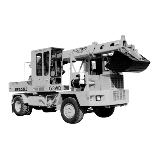
OPERATOR'S MANUAL
Form #29807
G3WD
E SERIES
7739-4006
July 2002
Upperstructure
Starting S/N 0134371
Undercarriage
Starting S/N G03319
Also Covers
Upperstructure
0132371
Undercarriage
G03317
GRADALL
406 Mill Avenue S.W.
New Philadelphia, OH, 44663, USA
Telephone: (330) 339-2211
Fax: (330) 339-3579
Original Issue 11/98
Advertisement

Related Manuals for Gradall G3WD E Series


Summary of Contents for Gradall G3WD E Series
- Page 1 E SERIES 7739-4006 July 2002 Upperstructure Starting S/N 0134371 Undercarriage Starting S/N G03319 Also Covers Upperstructure 0132371 Undercarriage G03317 Form #29807 Original Issue 11/98 GRADALL 406 Mill Avenue S.W. New Philadelphia, OH, 44663, USA Telephone: (330) 339-2211 Fax: (330) 339-3579...
- Page 4 Strict attention to, and compliance with, instructions provided in this manual as well as the EMI & Gradall Hydraulic Excavator Safety Manuals and all instructional decals and plates affixed to the machine, will help you avoid personal injury and damage to the equipment. The information provided is not intended to cover all situations;...
- Page 6 The PIN plate is components literature. located on front center portion of upperstructure frame. You must read and understand the Gradall Opera- tion Manual and Safety Manuals before operating the machine. If you have any questions regarding the Gradall Excavator, contact your Gradall Distributor;...
- Page 7 SAFETY HIGHLIGHTS Read and understand this manual, and Gradall and EMI Hydraulic Excavator Safety Manuals and all instructional decals and plates before starting, operating or performing maintenance procedures on this equipment. KEEP THESE MANUALS IN CAB. Watch for these symbols; they are used to call your attention to safety notices.
- Page 8 SAFETY HIGHLIGHTS Learn to recognize ‘PINCH POINTS’ Boom Cradle Counterweight & Another Object Boom Holes Boom Upperstructure & Carrier Bucket & Linkage Learn to recognize “PINCH POINTS” and stay clear of them. Getting caught In a pinch point can cause serious injury or death.
- Page 9 If it differs, or if you aren’t sure, machine. Such items can cause other workers to contact your Gradall distributor before you run approach the machine without your knowledge and your unit.
- Page 10 SAFETY HIGHLIGHTS Learn and follow your employer’s safety rules. Be particularly careful if this is not the machine you usually operate. Read the manuals listed on DANGER page 2 and then operate the unit in a safe, open area to become familiar with the controls. Whenever rotating equipment (such as a mower or mixer) is installed on machine, adequate shielding must be installed to...
- Page 11 Center boom fully over rear of chassis and rest If one or more wheels indicate brake failure, boom or bucket on the ground. DO NOT DRIVE THE GRADALL HYDRAULIC EXCAVATOR. Investigate and correct. For Apply down pressure with boom (but not assistance, contact your Gradall Distributor.
- Page 12 SAFETY HIGHLIGHTS Do not operate with by standers or other workers near machine. Watch out for carrier cab when swinging. Position unit so that it won’t be necessary to swing close to cab. Attach load only as shown. Lift Capacity Chart values are based on load hanging vertically from tool eye as shown.
- Page 13 SAFETY HIGHLIGHTS GRADALL LIFTING CAPACITIES Avoid injury! Always relieve pressure trap- RATED LIFT CAPACITY ped in circuits before disconnecting, re- moving or installing hydraulic components. Pressure can be maintained in hydraulic circuits long after the engine has been shut down. This pressure can cause oil (or items such as pipe plugs) to “shoot out”...
- Page 14 DECALS Decals Inside Carrier Cab WARNING REMOTE CONTROL PROCEDURE STOP MACHINE W E L D I N G M AY D A M A G E E L E C T R I C A L W I R E S , E N G I N E PLACE TRANSMISSION SHIFTER IN NEUTRAL E L E C T R O N I C S A N D N Y L O N A I R B R A K E H O S E S .
- Page 15 Decals Inside Carrier Cab (continued) NEW BRAKES NEED INCREASED STOPPING DISTANCE. BRAKE CAPABILITY WILL IMPROVE AFTER SEVERAL STOPS. DEATH FAILURE TO STOP MAY RESULT IN INJURY. 8060-3025 TO PLACE ANY PART OF THIS MACHINE OR LOAD WITHIN 10 UNLAWFUL FEET OF HIGH VOLTAGE LINES Located on cab wall OF UP TO 50,000 VOLTS.
- Page 16 Decals Inside Carrier Cab (continued) Located inside fuse cover Part No. 7738-9311...
- Page 17 Decals Outside Carrier Cab DO NOT GO NEAR LEAKS High Pressure oil easily punctures skin causing serious injury, gangrene or death. If injured, seek emergency medical help. Immediate surgery is required to remove oil. Do not use finger or skin to check for leaks. Lower load or relive hydraulic pressure before loosening fittings.
- Page 18 Decals Outside Carrier Cab STAY CLEAR OF MOVING USE TWO HANDS PARTS. FASTEN COVERS WHEN CLIMBING BEFORE STARTING ON MACHINE. ENGINE. READ SERVICE FALLING FROM MANUAL BEFORE SLIPPERY MACHINE ADJUSTING OR SURFACE MAY CAUSE SERVICING. MOVING SERIOUS INJURY PARTS CAN CAUSE OR DEATH.
- Page 19 Located inside cab Part No. 7739-3004 Located on joystick pedestal (SAE controls only) Part No.7738-3887 GRADALL G3WD HYDRAULIC REMOTE OPERATING CONTROLS (GRADALL TRADITIONAL CONTROL PATTERN) BUCKET OPEN BUCKET CLOSE RAISE BOOM LOWER BOOM SWING LEFT SWING RIGHT RETRACT BOOM EXTEND BOOM...
- Page 20 Decals Inside Upper Cab (continued) Located on cab wall (4x2 only) Located on cab wall Part No. 7733-3066 Part No. 7733-3069 (4x4 only) MANUALS TO PREVENT ENGINE RING GEAR DAMAGE, WAIT 10 SECONDS AFTER ENGINE ROTATION STOPS BEFORE ATTEMPTING TO RESTART. Located on manual holder 9103-3157 Part No.
- Page 21 Decals inside Upper Cab (continued) R E M O T E C O N T R O L P R O C E D U R E THE SYSTEM CONTROL WILL NOT BE TRANSFERED TO UPPER UNTIL KEY IS TURNED ON TURN KEY SWITCH TO START ENGINE.THE FOLLOWING WILL THEN OCCUR: A.
- Page 22 Decals In Upper Cab (continued) FOR SAFE OPERATION OF MACHINE AND TO MINIMIZE RISK OF SERIOUS I N J U R Y : BEFORE OPERATING,READ OPERATOR AND SAFETY MANUALS, UNDERSTAND ALL CONTROLS IN CAB AND CLEAR LOOSE OBJECTS OFF MACHINE, SOUND HORN BEFORE STARTING ENGINE.
- Page 23 Decals Outside Upper Cab OR INJURY MAY RESULT FROM DEALTH CONTACTING ELECTRICAL LINES. TO PLACE ANY PART OF THIS UNLAWFUL MACHINE OR LOAD WITHIN 10 FEET OF HIGH VOLTAGE LINES OF UP TO 50,000 VOLTS. FOR MINIMUM CLEARANCES OF HIGH VOLTAGE LINES IN EXCESS OF 50,000 VOLTS. SEE YOUR LOCAL STATE AND FEDERAL REGULATIONS.
- Page 24 Decals Outside Upper Cab (continued) WARNING CLAMP BOLT DO NOT RIDE ON EXCAVATOR OR TORQUE ATTACHMENTS. FALLS, ELECTRIC SHOCK OR CRUSHING COULD CAUSE SERIOUS 200 ft. lb. INJURY OR DEALTH 8090-3017 Located on both sides of tele. boom located on both sides of both boom clamps Part No.
- Page 25 CARRIER CAB CONTROLS, INSTRUMENTS & INDICATORS WATER WAIT TO ENGINE ENGINE REMOTE START BEAM STOP WARNING MAINT FUEL has been detected. Engine can be operated but fault must be REMOTE display glows red to indicate Remote/Travel switch is investigated and repaired at earliest opportunity. positioned for remote control operation.
- Page 26 UPPERSTRUCTURE CAB CONTROLS AND INSTRUMENTS Heater (optional) Mini-Siren (pulsing sound indicates engine Swing In/Out & Swing Joystick shutdown has been initiated - Steady sound Boom Tilt Switch indicates low air system pressure) Transmission Shift Switch Engine Stop Light (intermittent red light in- Horn Switch dicates that engine shutdown has been initiated) Boom Hoist &...
- Page 27 ENGINE OPERATION Checks & Services Before Starting Engine (To be performed at beginning of each work shift) Complete all required maintenance before operating unit. Inspect visually for damage, leaks, vandalism & Make sure remote switch is in travel position. needed maintenance. Check coolant level.
- Page 28 Normal engine operation Observe voltmeter, water temperature and oil overspeeding the engine (exceeding governed pressure gages frequently to be sure all engine RPM). The governor has no control over engine systems are functioning properly. speed when engine is being “pushed” by carrier load. Be alert for unusual noises or vibration.
- Page 29 CHECKS BEFORE DRIVING (To be performed at beginning of each work shift) Complete all required maintenance before driving. Check operation of horn and travel and back-up Check operation of steering while moving slowly alarm and any other signal devices. in first gear. Be alert for any increase in effort needed to turn wheels and any unusual steering response to normal steering effort.
- Page 30 BRAKE SYSTEM The air brake system includes a service brake, an emergency brake, a parking brake and a digging GREEN NEEDLE brake. FRONT PORTION OF SYSTEM ORANGE NEEDLE REAR PORTION LOW AIR OF SYSTEM INDICATOR DUAL AIR GAGE Wear seat belt to avoid being thrown from carrier driver’s seat during braking emergency.
- Page 31 BRAKE SYSTEM (Con’t.) EMERGENCY BRAKE APPLICATION (pressure lost in rear) If the air pressure gages indicate some system pressure remaining, it may be possible to drive the unit a short distance to remove it from a hazardous position (use first gear only). If carrier cannot be moved, direct traffic around carrier until warning flags, flares or lights can be displayed.
- Page 32 Digging brake (Con’t.) Remote control braking DIGGING BRAKE APPLICATION The digging brake is applied when operating in remote mode. The digging brake will be released and reapplied automatically as travel pedal in upper- REMOTE TRAVEL structure is actuated and released. SWITCH ON CARRIER DASH PULL TO APPLY...
- Page 33 STEERING SYSTEM Remote control steering Conventional steering Your unit is equipped with a travel/steering pedal The power steering system provides low effort in the upperstructure cab. The engine must be steering under normal conditions and greater running to provide power for remote control control in the event of a blowout or soft ground.
- Page 34 POWER TRAIN The power train furnished on 4 x 2 carriers (units Notify maintenance personnel of malfunction as having one driving axle at rear) includes the engine. soon as possible. torque converter, power shift transmission and the rear axle. It includes the drive shaft between the Four-Wheel-Drive Default (4 x 4 units only): Four- transmission and the rear axle.
- Page 35 Though it is permissible to use the braking power of speed when the engine is being pushed by the carrier the engine when traveling downhill, take care to load. Select an appropiate gear ratio and use your avoid overspeeding the engine (exceeding governed brakes to assist in showing the carrier.
- Page 36 REMOTE CONTROL NOTE: Remote control Is to be used for positioning unit at job site, not for over-the-road travel. Preparing Carrier for Remote Control Operation After reaching job site, perform following procedure Move transmission shift lever to NEUTRAL to prepare carrier for remote control travel. position.
- Page 37 Precautions for Remote Control Operation counterweight before starting to move. Be especially watchful for overhead wires and traffic. Always apply parking brake and stop Never tow load using remote control drive. engine before leaving upper cab. Always give audible signal before moving unit. Never permit bucket to drag while moving unit.
- Page 38 Depress TRAVEL portion of Remote/Travel Disengage differential lock and four-wheel drive switch. (refer to page 23 for procedure). PARKING THE GRADALL Precautions: A void parking on slopes or near an excavation. chine with boom in air. Avoid parking on roads or highways. If it can- Park on level ground and block wheels.
- Page 39 RETRACT BOOM BOOM Test your controls before operating. The control pattern illustrated is the standard Gradall control pattern. If your machine controls have been modified to any other pattern, be certain you are familiar with their functions before operating and ensure that control diagram In cab Is changed to show the actual pattern.
- Page 40 A TYPICAL GRADALL DIGGING CYCLE Pull back on left joystick (A) to raise boom from Move right joystick to left (G) to swing left or to boom rest. Be sure to raise boom far enough to right (H) to swing right to digging site.
- Page 41 A TYPICAL GRADALL DIGGING CYCLE While pushing forward on left joystick (B) to If required, press left side of tilt switch (I) to tilt lower boom and force bucket into ground, pull counterclockwise or right side of switch (J) to back on right joystick (E) to retract boom and tilt clockwise.
- Page 42 A TYPICAL GRADALL DIGGING CYCLE Move right joystick to left (C) to empty the Move right joystick to right (H) to swing right bucket. or to left (G) to swing left to dump site. If necessary, extend boom pushing right joystick forward (F).
- Page 43 LIFTING AND POSITIONING A LOAD Precautions Do not depend on machine tipping as a warning of Do not travel with a suspended load. Excava- overload. Some load ratings are based on hydraulic tors are not designed for pick and carry lifts. lift capacity, not stability.
- Page 44 General Planning A Lift The excavator can lift and position loads safely Determine the weight of the load. Weight of ONLY IF YOU PLAN THE LIFT PROPERLY. slings, chains and auxiliary lifting devices must be added as part of the load. Refer to lift capacity chart for weight adjustment required for bucket.
- Page 45 SLIDE-A-BOOM EXTENSION & RETRACTION The Slide-A-Boom feature enables the operator to quickly reposition the boom on the cradle to gain an additional four feet of reach. Failure to apply proper torque to cap screws Extending Slide-A-Boom in steps 9 and 10 can cause structural dam- Position unit on a level surface.
- Page 46 ATTACHMENT INSTALLATION Keep boom in fully extended position while installing bucket. Stay clear until bucket adapter has been fitted to bucket as shown in step 2. Digging with a loose or an improperly fitted bucket can shear adapter bolts and cause excessive wear.
- Page 47 Recommended Lubricants & Capacities Capacities Application Symbol Lube When Used Grade Specification English Liters GO (multi-purpose lube) All Year 85 w/ 140 27.7 pints 13.1 Differential, Front GO (multi-purpose lube) All Year 85 w/ 140 47.5 pints 22.5 Differential, Rear Engine Cooling System All Year 29 qts.
- Page 48 LUBRICATION & MAINTENANCE DIAGRAM SYMBOLS ATF - Automatic Transmission Fluid CG - Grease - Extreme Pressure GO - Multi-Purpose Lubricant DF - Diesel Fuel EO - Engine Oil GL - Open Gear Lube HF - Hydraulic Fluid HTF - Hydraulic Transmission Fluid •...
- Page 49 LUBRICATION & MAINTENANCE No. of No. of Points Points Item Lube Item Lube Symbol 4 x 2 4 x 4 Symbol 4 x 2 4 x 4 Daily Lubrication & Maintenance Monthly Lubrication and Maintenance Cont. Tool Link Pin Oil Cooler (inspect fins & clean as req’d) Tool Cylinder Pivot Pins Engine Drive Belts (Check condition &...
- Page 50 TORQUE CHECK SCHEDULE TORQUE FASTENER FREQUENCY TYPE ITEM Newton- (QUANTITY) FOOT-POUNDS Metres Semi- First Monthly Annually Screw Min. Max. Min. Max. 30 Days UPPERSTRUCTURE Boom In/ Out Cylinder Rod Boom In/Out Cylinder Ball Joint Boom Retainer Brackets Boom Rollers Boom Stop Blocks Swing Bearing Swing Motor Swing Pinion Gear...
- Page 51 CHECKING AUTOMATIC SLACK ADJUSTERS IMPORTANT NOTES With brake system fully charged (125 psi), apply digging brake and stop engine. Brake actuator chambers on your unit provide visual Install wheel chocks to prevent carrier movement. indication that automatic slack adjusters are, or are Inspect all actuator push rods to determine position not, working properly.
- Page 52 EXCAVATOR HAND SIGNALS Standard Signals - When excavator work conditions require hand signals, they shall be provided or posted conspicuously for the use both signalman and operator. No excavator motions shall be made unless signals are clearly understood by both signalman and operator.
- Page 53 THIS FAR TO GO - With hands raised and open MOVE SLOWLY - Place one hand motionless in CLOSE BUCKET - Hold one hand closed and front of hand giving motion signal. (Raise load inward, move hands laterally, indicating distance to stationary.
Need help?
Do you have a question about the G3WD E Series and is the answer not in the manual?
Questions and answers