Advertisement
Quick Links
Advertisement

Related Manuals for AccuAir AA-5157


Summary of Contents for AccuAir AA-5157
- Page 1 AA-5157 2020-PRESENT JEEP GLADIATOR (JT, MOJAVE) AIR SUSPENSION SYSTEM INSTALLATION GUIDE 29-21019...
- Page 2 Alignment must be performed at POSITION 2 immediately after installation. NOTICE TO THE INSTALLER: This suspension kit is installed differently than most suspension kits. We will have you install electrical and airlines first. Then you will install suspension system parts. AA-5157 Installation Guide...
- Page 3 © and following all instructions and product safety messaging below. If you have further questions contact us at: sales@AccuAir.com. Our team is here to help. A FEW WORDS ABOUT PRODUCT SAFETY Before installation, please take a moment to review the following safety information and installation instructions.
- Page 4 BUCKLE UP & USE supplemental restraints. • Consult the AccuAir installation manual ® (sales@AccuAir.com) & OEM off road supplement for additional safety information. WARNING: This advanced AccuAir ® JT kit requires professional installation with access to a two-post vehicle lift. Experience with Jeep JT suspension, electrical wiring, Jeep maintenance recommendations, safety messaging, torque &...
- Page 5 Contact your local Jeep dealer. • After installation, a qualified alignment facility is required to align the vehicle to the OEM specification. If you have any questions or reservations about installing this product, contact AccuAir Customer Service. Tech: 888.234.6698 REV 01 | 02/26/2024...
- Page 6 Subject to the terms, exclusions and limitations herein, Arnott, LLC. (“Warrantor” or “AccuAir”) exclusively warrants to the initial retail purchaser of a AccuAir Jeep JT suspension kit that AccuAir will according to terms herein, repair defects in or replace AccuAir supplied components which, upon AccuAir inspection are determined to have defects in materials or workmanship existing as of the date of sale to the initial retail customer (hereafter “Customer”).
- Page 7 OTHER EXCLUSIONS –LIMITATION OF DAMAGES - YOUR RIGHTS UNDER STATE LAW. No employee, other agent of AccuAir or authorized reseller may, amend or waive this written Limited Warranty or make additional representations or warranties regarding any AccuAir features, performance, workmanship or materials.
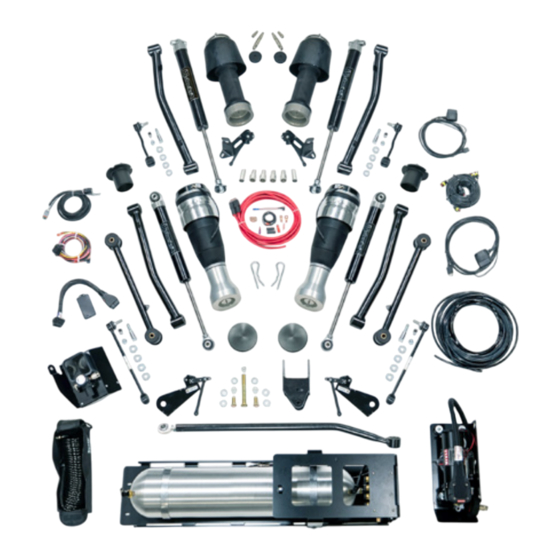
- Page 8 20-19835 JEEP JT CONTROL ARM KIT ASSEMBLY 20-19840 JEEP JT SHOCK KIT 20-19836 JEEP INFLATION ACCESSORY KIT 20-19830 FOR A FULL BREAKDOWN OF PARTS INCLUDED IN EACH BOX, PLEASE REFER TO THE PARTS APPENDIX ON PAGE 77. AA-5157 Installation Guide...
- Page 9 REQUIRED TOOLS SAE & SAE Hex Key Sockets/Wrenches (5/32”, 7/32” & 5/16” Hex Key Sockets, 7/16”, 1/2”, 9/16”, 3/4”, 13/16”, 7/8” & 1-1/8”) Metric & Metric Hex Key Sockets/Wrenches (6mm Hex Key Socket, 8mm, 10mm, 13mm, 15mm, 18mm, 19mm, 21mm, 22mm & 24mm) Allen Wrenches (4mm, 5mm &...
- Page 10 WIRE TERMINATION POINTS Ride Height Sensor - 2 Front Right Fuse (70 AMP) Fuse Box Battery (Ignition Fuse Tap - F52) F102 F103 F104 F105 F107 F108 Touchpad (Route to Desired Location) Ride Height Sensor - 1 Front Left AA-5157 Installation Guide...
- Page 11 Battery & ECU Ride Height Chassis Sensor - 4 Ground Rear Right Compressor Compressor Output Compressor Bolt Ground Lug (On Side of Frame) Purge Valve Manifold Pressure Sensor Bolt Ground Lug (On Upper Air Tank Bracket) Relay Ground Lug (In Vehicle) Input to Headlight (For TouchPad...
- Page 12 FUSE BOX TAP INTO TAP INTO F52 OBD II Port Fuse Box (Ignition Fuse Tap - F52) F102 F103 F104 F105 F107 F108 Speed Module Ignition Wire Tap AA-5157 Installation Guide...
- Page 13 Compressor Relay Tech: 888.234.6698 REV 01 | 02/26/2024...
- Page 14 SPEED MODULE ROUTING CB02 F109 CB03 F110 F111 F100 F106 F101 AA-5157 Installation Guide...
- Page 15 CB01 F45 F43 Tech: 888.234.6698 REV 01 | 02/26/2024...
- Page 16 PLUMBING ROUTING Air Spring - 2 Front Right ViAIR Residual Compressor Pressure Union Intake Filter Residual Pressure Union Air Spring - 1 Front Left AA-5157 Installation Guide...
- Page 17 Air Spring - 4 Rear Right Compressor VU4 Air Line Supply From Tank Regulator Air Spring - 3 Rear Left Tech: 888.234.6698 REV 01 | 02/26/2024...
- Page 18 WIRING 1. Locate the 6 gauge power wire in Box 1. (Figure 1) FIGURE 1 AA-5157 Installation Guide...
- Page 19 2. Lay the fuse on top of the battery and route remaining wire along the passenger side frame rail to the floor drain plug underneath the center of the vehicle. Do not connect to battery at this time. (Figure 2) FIGURE 2 Tech: 888.234.6698 REV 01 | 02/26/2024...
- Page 20 FIGURE 4 Locate the rubber plug in the floor located above the fuel tank, toward the passenger side, under the rear seat. Remove and install supplied grommet (Box 1, Bag 20-18283). (Figures 5, 6) FIGURE 5 FIGURE 6 AA-5157 Installation Guide...
- Page 21 5. Pull the ECU main harness plug (Box 1), valve harness plug (Box 1), compressor power cable (Box 1), battery power cable (Box 1), and height sensor harness plug (Box 1) into the cab via the grommeted floor pan hole. Run an end of the 1/4”...
- Page 22 WIRING FIGURE 10 FIGURE 11 AA-5157 Installation Guide...
- Page 23 STORE EXCESS WIRING UNDER THIS AREA FIGURE 12 6. Gather all wire harnesses plus the 1/4” air tubing and bundle them behind the carpet. (Figure 13) Also add TouchPad cable (white connector - Found in Box 2). (Figure 14) FIGURE 13 Tech: 888.234.6698 REV 01 | 02/26/2024...
- Page 24 Find the ECU assembly in Box 3 (Figure 15). Make electrical connections as shown in Figure 16. Refer to relay diagram to make relay connections (Figure 17). Connect 1/4” air line to the pressure regulator. FIGURE 15 AA-5157 Installation Guide...
- Page 25 FIGURE 16 Battery & ECU Chassis Ground Compressor Compressor Output Compressor FIGURE 17 Bolt Ground Lug (On Side of Frame) Tech: 888.234.6698 REV 01 | 02/26/2024...
- Page 26 They will go on the stud as pictured. Thread and tighten supplied nut and washer on the stud using a 10mm socket/wrench. (Figure 18) FIGURE 18 9. Run the orange ignition wire from the ECU and the black 2-pin connector under the driver side kick panel toward the driver floorboard. (Figure 19) FIGURE 19 AA-5157 Installation Guide...
- Page 27 10. Route the orange ignition wire from the driver side kick panel up to the fuse box under the hood on the passenger side. (Figure 20) FIGURE 20 11. Crimp the orange ignition wire to the fuse tap provided in Box 1, Bag 20-18283. Extract 20 AMP fuse from F52 and place on bottom position of the fuse tap.
- Page 28 13. Install the speed module using hardware from the box labeled Box 4. The supplied speed module must be installed to allow full functionality of the system. View video using QR code to the right for installation process, or use the following instructions. SPEED MODULE VIDEO AA-5157 Installation Guide...
- Page 29 14. Connect the HDMI connector to black box and the female OBD2 connector to the male end of the Y-Cable with the flying gray lead. See below. (Figure 23) FIGURE 23 15. Bring the harness assembly to the driver’s side kick panel. Connect the black 12-pin Molex to the black box. (Figure 24) FIGURE 24 Tech: 888.234.6698 REV 01 | 02/26/2024...
- Page 30 16. Unhook the male OEM CAN bus connector from under the driver’s side and connect to the female end of the Y-Cable. (Figures 25, 26) FIGURE 25 FIGURE 26 17. Take the remaining male CAN bus connector from the Y-Cable and locate it in the OEM CAN bus bracket. (Figures 27, 28) FIGURE 27 FIGURE 28 AA-5157 Installation Guide...
- Page 31 18. Locate the T-tap in Box 1, Bag 20-18283, install on the orange ignition wire near the driver’s side kick panel and connect the gray flying lead wire from the CAN bus Y-Cable. (Figures 29, 30) FIGURE 29 FIGURE 30 19.
- Page 32 20. Remove the glove box by pressing on the plastic live latch. (Figures 33, 34) FIGURE 33 FIGURE 34 21. Take the two-pin wire and connect it into any open position on the green communication bus. (Figures 35, 36) FIGURE 35 FIGURE 36 AA-5157 Installation Guide...
- Page 33 Locate the air tank bracket and spacer in Box 5. Using a 5mm Allen wrench and 13mm socket/wrench, separate the upper and lower brackets and retain the hardware. (Figures 37, 38) Using a 19mm socket/wrench, remove the spacer (Figure 39) and associated hardware. FIGURE 37 FIGURE 38 Install the upper part of the air tank bracket with VU4 manifold attached.
- Page 34 Snug bolt using a 19mm socket/wrench. Do not completely tighten at this time. You will come back and tighten this bolt after the lower bracket is installed. (Figures 40, 41) FIGURE 40 FIGURE 41 Connect VU4 harness at this time. (Figures 42, 43) ECU INSIDE CAB VU4 OUTSIDE CAB FIGURE 42 FIGURE 43 AA-5157 Installation Guide...
- Page 35 Run 1/4” tubing (Box 6) from the VU4 to all four spring locations. This is also a good time to run the ride height sensor wires to their locations. Run in a safe location away from heat and objects that will pinch or chafe the lines/wires.
- Page 36 Thread supplied 15mm head bolts (Box 7) into existing threaded holes on passenger rear of frame. The bracket will slide over these bolts. Install the compressor bracket. Ensure the leader hose from the compressor is routed above the frame. (Figures 46, 47, 48) FIGURE 46 FIGURE 47 AA-5157 Installation Guide...
- Page 37 FIGURE 48 Ground the compressor to the frame using the factory bolt located in front of the compressor mounting location using a 13mm socket/wrench. (Figures 49, 50) FIGURE 49 FIGURE 50 Tech: 888.234.6698 REV 01 | 02/26/2024...
- Page 38 13mm socket/wrench. Two bolts in the front of the brackets utilize factory threaded holes in the transmission cross-member. (Figure 51, 52, 53) FIGURE 51 FIGURE 52 FIGURE 53 (USE BLUE LOCTITE WHEN INSTALLING THE M8 FASTENERS TO THE FACTORY CROSSMEMBER) NOTE: Finish tightening the upper tank bracket mounting bolt at this time. AA-5157 Installation Guide...
- Page 39 Plug in tank pressure sensor located on the front of the air tank. (Figure 54) FIGURE 54 Plug in the tank purge valve. (Figure 55) FIGURE 55 Tech: 888.234.6698 REV 01 | 02/26/2024...
- Page 40 Nyloc nut with a 13mm socket/wrench. (Figures 56, 57) FIGURE 56 FIGURE 57 Run 3/8” tubing (Box 1) from VU4 supply to tank. Use provided air line cutter to cut tube to length. (Figures 58, 59) FIGURE 58 AA-5157 Installation Guide...
- Page 41 FIGURE 59 Run 3/8” tubing (Box 1) from push-to-connect on the compressor leader hose to the air tank. (Figures 60, 61) FIGURE 60 Tech: 888.234.6698 REV 01 | 02/26/2024...
- Page 42 FIGURE 61 Run the 3/8” tubing (Box 1) from the intake of the compressor to the air box area under the hood and install ViAIR compressor filter (Box 7), which has a push-to-connect fitting. (Figure 62) FIGURE 62 AA-5157 Installation Guide...
- Page 43 Connect 1/4” air line to the front of the air tank. This is the line running through the rubber grommet that connects to the pressure regulator inside the cabin. (Figure 63) FIGURE 63 Ensure 1/4” tubing from the air tank to the push-to-connect fitting on the regulator for the inflation system is secure.
- Page 44 FIGURE 65 FIGURE 66 Replace the bolt storage bin behind the ECU bracket. Make sure both grounds are still in position before tightening with a T40 torx bit and 10mm socket/wrench. (Figures 67, 68) FIGURE 67 FIGURE 68 AA-5157 Installation Guide...
- Page 45 40. Hook up the main power by terminating the short leg of the power cable (Ring terminal found in Box 1, Bag 20-18283). Remove the 70 amp fuse from the holder. Connect to the battery. Then, reinstall the 70 amp fuse. (Figures 69, 70, 71) FIGURE 69 FIGURE 70...
- Page 46 Remove the front tires/wheels using a 22mm socket. Remove OEM front sway bar end links using a 6mm hex key socket/wrench & 18mm socket/wrench. (Figure 72) FIGURE 72 Disconnect OEM front track bar from frame using a 21mm socket/wrench. (Figure 73) FIGURE 73 AA-5157 Installation Guide...
- Page 47 Disconnect OEM front shock from upper shock tower mount & lower axle mount using a 18mm socket/wrench and retain the hardware. (Figure 74) FIGURE 74 Disconnect OEM front brake line brackets from OEM front lower control arms using a 15mm socket/wrench. (Figure 75) FIGURE 75 Tech: 888.234.6698...
- Page 48 Locate the air springs in Boxes 9 & 10, Sub-box 20-15758. Attach a 48” section of 1/4” air line from Box 1 to inside of air spring top. The air springs have a push-to-connect fitting. (Figures 79, 80) FIGURE 79 FIGURE 80 AA-5157 Installation Guide...
- Page 49 Insert a Mojave Top Mount (Box 8) into the top of each air spring, ensuring the air line goes through the top mount. (Figures 81, 82) FIGURE 81 FIGURE 82 Install the new air springs with the air line going through the top mount hole of the frame. (Figure 83) FIGURE 83 Tech: 888.234.6698 REV 01 | 02/26/2024...
- Page 50 (Box 10, Bag 21-17854) with a 13mm socket/wrench on the air spring. Tighten to 17 ft-lbs. (Figures 84, 85) FIGURE 84 FIGURE 85 Install top cap (Box 10, Bag 21-17854) with the air line passing through the center. Seat the cap on the top mount. (Figures 86, 86) FIGURE 86 FIGURE 87 AA-5157 Installation Guide...
- Page 51 One at a time, remove the OEM front lower control Install the new front lower control arms with the NOTE: arms & install the new front lower control arms (Box offset bend toward the inside of the vehicle. 11) using the OEM hardware, a 21mm socket/wrench, & 24mm socket/wrench.
- Page 52 AIR SPRING PLUMBING Using the residual pressure union (Box 10, Bag 21-17854), connect the 1/4” air line from the air spring and 1/4” air line from the VU4. (Figure 89) AIR SPRING AIR SPRING MANIFOLD MANIFOLD FIGURE 89 AA-5157 Installation Guide...
- Page 53 WARNING: Never lower vehicle to the ground without air springs being fully inflated. Start vehicle and inflate with TouchPad Controller. Inflate front springs using TouchPad Controller. Ignition must be on. Inflate by tapping the double up arrow. (Figure 90) FIGURE 90 Tech: 888.234.6698 REV 01 | 02/26/2024...
- Page 54 HEAT SHIELD NOT HEAT SHIELD NOT SHOWN FOR SHOWN FOR CLARITY CLARITY FIGURE 91 - RIGHT FRONT FIGURE 92 - RIGHT FRONT When installed it should look as shown. (Mount link to lower control arm.) (Figure 93) FIGURE 93 AA-5157 Installation Guide...
- Page 55 NOTICE: If lowering vehicle before moving onto rear installation, front air springs MUST be inflated. Failure to inflate will cause air spring damage which will not be covered by warranty. Install Front Brake Line Bracket to front lower control arm with OEM hardware using a 15mm socket/wrench. (Figure 94) Connect OEM front brake line bracket to bracket using supplied 1/4”...
- Page 56 If they do, skip Steps 22 - 28. If they do not, proceed with Steps 22-28. Locate the four top and two bottom Mojave-specific bushing inserts (Box 8) (Figure 95) and JRi front shocks (Box 12). BOTTOM BOTTOM FIGURE 95 AA-5157 Installation Guide...
- Page 57 One one shock, remove the urethane and steel bushings from either side of the top mount. (Figures 96, 97) FIGURE 96 FIGURE 97 If the inserts will not pull out by hand, gently pry the busings off using a thin-bladed screwdriver or similar. (Figures 98, 99) FIGURE 98 FIGURE 99...
- Page 58 FRONT INSTALLATION You will notice the Mojave-specific inserts are thinner than those just removed. Press them into the bushings. Then, insert the bushings into the top mount. (Figures 100, 101, 102) FIGURE 100 FIGURE 101 FIGURE 102 AA-5157 Installation Guide...
- Page 59 Flip the shock over, and note the orientation of the bushings, bottom mount, and insert. If the bushing will not pull off of the insert, gently pry the bushing off using a thin-bladed screwdriver or similar. (Figures 103, 104, 105) FIGURE 103 FIGURE 104 FIGURE 105...
- Page 60 To set bushings properly for ride height, these will be tightened once vehicle is on ground with full vehicle weight on tires/wheels. WARNING: Only use JRi Shocks for this vehicle. Use of other shocks can cause air spring failure. AA-5157 Installation Guide...
- Page 61 Install front tires/wheels using a 22mm socket Lower vehicle to ground. Torque lug nuts to 130 ft-lbs. Make sure that tires/wheels are pointed straight ahead. NOTE: Do not tighten at this time. Install fixed end of Front Adjustable Track Bar (Box 11) to frame with OEM hardware using a 21mm socket/ wrench.
- Page 62 18265) onto rod end of track bar. Install rod end assembly into front axle mount with OEM hardware using a 21mm socket/wrench. (Figure 109) FIGURE 109 WARNING: Only use supplied track bar. Use of any other may cause instability. AA-5157 Installation Guide...
- Page 63 Install new front sway bar end links (Box 11). (Figure 110) 2024+ model year, use supplied sleeves (Box 11) to mount sway bars. (Figure 111) FIGURE 110 FIGURE 111 NOTE: It may be necessary to turn steering wheel to align track rod end with mount. Check front of vehicle to make sure body is centered over front tires/wheels.
- Page 64 (Figures 112, 113) FIGURE 112 FIGURE 113 To gain access to the upper shock bolts, the fender liner can be pulled back to allow a wrench to loosen the shock. (Figure 114) FIGURE 114 AA-5157 Installation Guide...
- Page 65 Remove factory shocks using a 21mm socket/wrench. This will allow the rear axle to droop enough to remove the factory coil springs. (Figures 115, 116) FIGURE 115 FIGURE 116 Lower the rear axle and remove the rear coil springs and rubber spring isolators. (Figures 117, 118) FIGURE 117 FIGURE 118 Tech: 888.234.6698...
- Page 66 One at a time, remove and replace the rear arms, starting with the upper arms first using a 21mm socket/wrench. (Figures 121, 122, 123, 124, 125, 126, 127, 128) All replacement arms can be found in Box 11. FIGURE 121 FIGURE 122 AA-5157 Installation Guide...
- Page 67 FIGURE 123 FIGURE 124 FIGURE 125 FIGURE 126 Tech: 888.234.6698 REV 01 | 02/26/2024...
- Page 68 21mm socket/wrench. Ensure the locating tabs on the height sensor bracket are sitting against the mount. When installing the upper link bar, the welded tab for height sensor linkage should be on top and towards the frame. (Figure 129) FIGURE 129 AA-5157 Installation Guide...
- Page 69 After you finish installing all four rear arms, connect the rear height sensor linkage to the upper arm using the supplied hardware and spacer. (Figures 130, 131) FIGURE 130 FIGURE 131 Locate air spring straps (Box 10, Air Spring Box B, Bag 21-17854) (Figure 132) Using a 13mm socket/wrench, attach end with 90°...
- Page 70 Ensure locating tabs are on the outside of this bracket (towards center of the axle). (Figures 135, 136) NOTCH IN AIR SPRING LOCATING TAB ON NEEDS TO LINEUP WITH OUTSIDE OF FLANGE NOTCH IN PERCH, FACING REAR OF VEHICLE FIGURE 135 FIGURE 136 AA-5157 Installation Guide...
- Page 71 Connect the 1/4” air line from appropriate valve location to the top of the air spring. Then push the top of the air spring into the factory spring pocket and install the retaining clip (Box 2, Air Spring Box B, Sub-box 21-17854) as pictured.
- Page 72 Supply From Tank Residual Regulator Pressure Union Air Spring - 3 Air Spring - 1 Rear Left Front Left Install new rear sway bar end links found in Box 11, reusing the OEM hardware. (Figure 139) FIGURE 140 AA-5157 Installation Guide...
- Page 73 Install the track bar relocation bracket to the rear axle using the supplied hardware (Box 11) and spacers through the factory mounting hole using a 21mm socket/wrench and a 17mm socket/wrench. (Figures 141, 142) FIGURE 141 FIGURE 142 Ensure the flange pictured is sitting flush to the factory bracket. Drill two 12mm (21/64”) holes and install bolts. At this time, you can reinstall the track bar to the new mounting location, using OEM hardware and a 21mm socket/wrench.
- Page 74 Install the rear bump stop extensions (Box 9) using supplied hardware with a 13mm wrench. (Figures 145, 146) FIGURE 145 FIGURE 146 WARNING: Never lower vehicle to the ground without air springs being fully inflated. Start vehicle and inflate with TouchPad Controller. AA-5157 Installation Guide...
- Page 75 16. Inflate rear springs using TouchPad Controller. Ignition must be on. Inflate by tapping the double up arrow. (Figure 147) FIGURE 147 17. Install rear tires/wheels using a 22mm socket. 18. Lower vehicle to ground. Torque lug nuts to 130 ft-lbs. AFTER INSTALLATION, VEHICLE MUST BE PROFESSIONALLY ALIGNED BY ALIGNMENT CENTER.
- Page 76 Sway bar end link mount using a 18mm socket/ Before driving, it is necessary that the wrench. Torque to 59 ft-lbs. steering wheel and wheels are straight at position two. Adjust drag length accordingly. Vehicle must be professionally aligned. AA-5157 Installation Guide...
- Page 77 You will need to do this periodically depending on how much use the vehicle has. Generally, once every two AccuAir advises against adjusting the weeks will be adequate but that can vary. regulator over 150 psi.
- Page 78 3/8 HEAT SHRINK (NBI4494001) 29-18282 RELAY GRD HARNESS, 24" 29-18354 RUBBER GROMMET 29-16095 HEIGHT 4-CORNER SENSOR HARNESS 29-16265 WIRE KIT POWER HARNESS 29-16548 PLASTIC AIRLINE CUTTER 29-16878 3/8 INCH DOT AIR LINE 29-17530 8" ZIP TIES, 50 PACK AA-5157 Installation Guide...
- Page 79 BOX 1 JEEP JT WIRING & PLUMBING KIT BOX 1 ITEM # DESCRIPTION 29-18212 JEEP KIT E-PLUS MAIN HARNESS 29-18239 ECU TO VU4 HARNESS, 6.5 FEET 29-18680 COMPRESSOR POWER EXTENSION CABLE (8FT) 29-18861 1/4 INCH DOT AIR LINE 29-20742 SNOOP, LIQUID LEAK DETECTOR, 2 OUNCE BOX 2 TPAD ASSEMBLY BOX 2...
- Page 80 1/4" PUSH-TO-CONNECT TO SEALED 1/8" NPT STRAIGHT FITTING 29-17024 SEAMLESS ALUMINUM TANK WITH 51/4" PORTS WITH HARDWEAR 32" X 6.625" 29-17872 JT 5 GAL TANK BRACKET FRAME MOUNT 29-18109 SOLENOID VALVE 29-18159 #8-32 X 3/8" BUTTON HEAD SCREW HEX DRIVE AA-5157 Installation Guide...
- Page 81 BOX 5 JEEP JT INFLATION BRACKET ASSEMBLY BOX 5 ITEM # DESCRIPTION 29-18160 M8 X .1.25 X 20 BUTTON HEAD SCREW HEX DRIVE 29-18163 #40-24 X 1.75" BUTTON HEAD SCREW HEX DRIVE 29-18164 M8 NYLON-INSERT LOCKNUT (NYLOC) 29-18167 1/4" TO 1/8" FNPT BUSHING 29-18168 1/4"...
- Page 82 JEEP JT REAR BUMP STOP SPACER ASSEMBLY 20-17452 JEEP JL/JT RIDE HEIGHT SENSOR ASSY FRONT LEFT 20-17453 JEEP JL/JT RIDE HEIGHT SENSOR ASSY FRONT RIGHT 20-17613 JEEP JT RIDE HEIGHT SENSOR ASSY, REAR RIGHT 20-17614 JEEP JT RIDE HEIGHT SENSOR ASSY, REAR LEFT AA-5157 Installation Guide...
- Page 83 FOLDER MODIFIED VEHICLE VISOR WARNING 29-18914 STICKER 29-19244 ACCUAIR 5" TALL VERTICAL DIE CUT 29-19804 ACCUAIR 5" DIE CUT STICKER - WHITE BOX 10 JEEP JT AIR SPRING KIT, BOX B BOX 10 ITEM # DESCRIPTION 20-15758 JEEP JL/JT AIR SPRING, FRONT...
- Page 84 29-17495 0.066" THK 29-17501 10-32 X 1" LG SHCS 29-18330 10-32 X 1-3/4" SHCS 29-18331 1" SPACER, FOR #10 SCREW, 5/16" OD 10-32 HEX NYLON-INSERT LOCKNUT 29-2702 (NYLOC) 29-6060 M6X1 NUT 29-19245 ACCUAIR 23" WIDE WHITE BANNER AA-5157 Installation Guide...
- Page 85 JTG REAR LOWER LINK 2-4.5" 29-18465 JTG REAR TRACK BAR BRACKET 29-18468 HDWR BG: JT REAR TRK BAR BK 29-20436 ACCUAIR CONTROL ARM BADGE 29-20458 JEEP JT DRIVER REAR UPPER LINK 29-20459 JEEP JT PASSENGER REAR UPPER LINK 29-20735 JEEP 2024+ SWAY BAR SPACER...
- Page 86 PARTS APPENDIX BOX 13 JEEP INFLATION ACCESSORY KIT BOX 13 ITEM # DESCRIPTION 29-18105 BLOW GUN 29-18125 CLIP ON SCHRADER CONNECTION 29-18126 30FT BRAIDED HOSE 29-18131 1/4" NPT QUICK CONNECT STUD (M) AA-5157 Installation Guide...
- Page 87 Tech: 888.234.6698 REV 01 | 02/26/2024...
- Page 88 TROUBLESHOOTING & TECHNICAL SUPPORT MORE INFO? ACCUAIR DOCUMENT LIBRARY www.AccuAir.com 888.234.6698 Monday - Friday 8:00AM - 6:00 PM (EST) 200 Sea Ray Drive, Merritt Island, FL 32953...
Need help?
Do you have a question about the AA-5157 and is the answer not in the manual?
Questions and answers