
Related Manuals for AccuAir AA-4279


Summary of Contents for AccuAir AA-4279
- Page 1 AA-4279 2019-PRESENT JEEP GLADIATOR (JT) AIR SUSPENSION SYSTEM INSTALLATION GUIDE 29-18893...
- Page 2 © and following all instructions and product safety messaging below. If you have further questions contact us at: sales@AccuAir.com. Our team is here to help. Wire Termination Points, Fuse Box, Speed Module Routing & Plumbing Routing Diagrams A FEW WORDS ABOUT PRODUCT SAFETY Wiring Before installation, please take a moment to review the following safety information and installation instructions.
- Page 3 After installation, a qualified alignment facility is required to align the vehicle to the OEM specification. to approx. 4.0” by system speed & ride height sensors. REPLACE & DO NOT USE ON ROAD IF SPEED SENSOR If you have any questions or reservations about installing this product, contact AccuAir Customer Service. DAMAGED/INOPERATIVE. •...
- Page 4 Any claim to enforce an arbitration award or for other breach or damages under this Limited to the initial retail purchaser of a AccuAir Jeep JT suspension kit that AccuAir will according to terms herein, repair Warranty can only be brought in a court of competent jurisdiction closest to Brevard County, Florida.
-
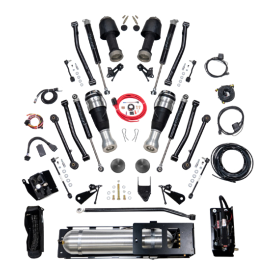
Page 5: Included Parts
FOR A FULL BREAKDOWN OF PARTS INCLUDED IN EACH BOX, Wire Brush PLEASE REFER TO THE PARTS APPENDIX ON PAGE 71. Wire Barrel Crimper Wire Stripper Heat Gun T40 Torx Bit Air Compressor Rubber-Tipped Air Inflator AA-4279 Installation Guide Tech: 888.234.6698 REV 07 | 02/14/2024... - Page 6 (On Upper Air Tank Bracket) Relay Ground Lug (In Vehicle) Ride Height Sensor - 1 Input to Front Left Headlight (For TouchPad Ride Height Dimming Optional) Sensor - 3 Rear Left AA-4279 Installation Guide Tech: 888.234.6698 REV 07 | 02/14/2024...
- Page 7 FUSE BOX TAP INTO TAP INTO F52 Compressor OBD II Port Fuse Box (Ignition Fuse Tap - F52) F102 F104 F103 F105 F107 F108 Relay Speed Module Ignition Wire Tap AA-4279 Installation Guide Tech: 888.234.6698 REV 07 | 02/14/2024...
- Page 8 SPEED MODULE ROUTING CB02 F109 CB03 F110 F111 F100 F106 F101 CB01 F45 F43 AA-4279 Installation Guide Tech: 888.234.6698 REV 07 | 02/14/2024...
- Page 9 Rear Right ViAIR Residual Compressor Pressure Union Intake Filter Compressor VU4 Air Line Supply From Tank Residual Regulator Pressure Union Air Spring - 3 Air Spring - 1 Rear Left Front Left AA-4279 Installation Guide Tech: 888.234.6698 REV 07 | 02/14/2024...
- Page 10 2. Lay the fuse on top of the battery and route remaining wire along the passenger side frame rail to the floor drain plug underneath the center of the vehicle. Do not connect to battery at this time. (Figure 2) FIGURE 1 FIGURE 2 AA-4279 Installation Guide Tech: 888.234.6698 REV 07 | 02/14/2024...
- Page 11 Remove and install supplied grommet (Box 1, Bag 20-18283). (Figures 5, 6) TANK PRESSURE INSIDE SWITCH OUTSIDE CAB ECU INSIDE CAB TANK PURGE VU4 OUTSIDE CAB VALVE FIGURE 8 FIGURE 9 FIGURE 5 FIGURE 6 AA-4279 Installation Guide Tech: 888.234.6698 REV 07 | 02/14/2024...
- Page 12 6. Gather all wire harnesses plus the 1/4” air tubing and bundle them behind the carpet. (Figure 13) Also add TouchPad cable (white connector - Found in Box 2). (Figure 14) FIGURE 11 FIGURE 13 AA-4279 Installation Guide Tech: 888.234.6698 REV 07 | 02/14/2024...
- Page 13 (Figure 17). Connect 1/4” air line to the pressure regulator. Battery & ECU Ride Height Chassis Sensor - 4 Ground Rear Right Compressor Compressor Output Compressor FIGURE 17 Bolt Ground Lug (On Side of Frame) FIGURE 15 AA-4279 Installation Guide Tech: 888.234.6698 REV 07 | 02/14/2024...
- Page 14 Pull the spare 5 (or 10) AMP fuse and position in top slot of the fuse tap. (Figure 21) FIGURE 19 FIGURE 21 AA-4279 Installation Guide Tech: 888.234.6698 REV 07 | 02/14/2024...
- Page 15 The supplied speed module must be installed to allow full functionality of the system. View video using QR code to the right for installation process, or use the following instructions. SPEED MODULE VIDEO FIGURE 24 AA-4279 Installation Guide Tech: 888.234.6698 REV 07 | 02/14/2024...
- Page 16 19. Route the two-wire cable from the driver’s side kick panel through the center console to the passenger side glove box. (Figures 31, 32) FIGURE 27 FIGURE 28 FIGURE 31 FIGURE 32 AA-4279 Installation Guide Tech: 888.234.6698 REV 07 | 02/14/2024...
- Page 17 21. Take the two-pin wire and connect it into any open position on the green communication bus. (Figures 35, 36) FIGURE 35 FIGURE 36 FIGURE 39 AA-4279 Installation Guide Tech: 888.234.6698 REV 07 | 02/14/2024...
- Page 18 Rear Left Front Left Connect VU4 harness at this time. (Figures 42, 43) 1 2 2 3 3 4 4 ECU INSIDE CAB VU4 OUTSIDE CAB FIGURE 42 FIGURE 43 FIGURE 44 AA-4279 Installation Guide Tech: 888.234.6698 REV 07 | 02/14/2024...
- Page 19 Install the compressor bracket. Ensure the leader hose from the compressor is routed above the frame. (Figures 46, 47, 48) FIGURE 49 FIGURE 50 FIGURE 46 FIGURE 47 AA-4279 Installation Guide Tech: 888.234.6698 REV 07 | 02/14/2024...
- Page 20 Plug in the tank purge valve. (Figure 55) FIGURE 53 (USE BLUE LOCTITE WHEN INSTALLING THE M8 FASTENERS TO THE FACTORY CROSSMEMBER) FIGURE 55 NOTE: Finish tightening the upper tank bracket mounting bolt at this time. AA-4279 Installation Guide Tech: 888.234.6698 REV 07 | 02/14/2024...
- Page 21 Run 3/8” tubing (Box 1) from push-to-connect on the compressor leader hose to the air tank. (Figures 60, 61) Run 3/8” tubing (Box 1) from VU4 supply to tank. Use provided air line cutter to cut tube to length. (Figures 58, 59) FIGURE 60 FIGURE 58 AA-4279 Installation Guide Tech: 888.234.6698 REV 07 | 02/14/2024...
- Page 22 (Box 7), which has a push-to-connect fitting. (Figure 62) Ensure 1/4” tubing from the air tank to the push-to-connect fitting on the regulator for the inflation system is secure. (Figure 64) FIGURE 62 FIGURE 64 AA-4279 Installation Guide Tech: 888.234.6698 REV 07 | 02/14/2024...
- Page 23 Replace the bolt storage bin behind the ECU bracket. Make sure both grounds are still in position before tightening with a T40 torx bit and 10mm socket/wrench. (Figures 67, 68) FIGURE 71 FIGURE 67 FIGURE 68 AA-4279 Installation Guide Tech: 888.234.6698 REV 07 | 02/14/2024...
-
Page 24: Front Installation
Disconnect OEM front brake line brackets from OEM front lower control arms using a 15mm socket/wrench. FIGURE 72 (Figure 75) Disconnect OEM front track bar from frame using a 21mm socket/wrench. (Figure 73) FIGURE 75 FIGURE 73 AA-4279 Installation Guide Tech: 888.234.6698 REV 07 | 02/14/2024... - Page 25 Locate the air springs in Boxes 8 & 9, Sub-box 20-15758. Attach a 48” section of 1/4” air line from Box 1 to inside of air spring top. The air springs have a push-to-connect fitting. (Figures 79, 80) FIGURE 83 FIGURE 84 FIGURE 79 FIGURE 80 AA-4279 Installation Guide Tech: 888.234.6698 REV 07 | 02/14/2024...
-
Page 26: Air Spring
INSTALL THE NEW FRONT LOWER CONTROL ARMS WITH THE OFFSET BEND CONTROL ARMS WITH THE OFFSET BEND TOWARD THE INSIDE OF THE VEHICLE. TOWARD THE INSIDE OF THE VEHICLE. FIGURE 87 AA-4279 Installation Guide Tech: 888.234.6698 REV 07 | 02/14/2024... - Page 27 CLARITY CLARITY FIGURE 90 - RIGHT FRONT FIGURE 91 - RIGHT FRONT When installed it should look as shown. (Mount link to lower control arm.) (Figure 92) FIGURE 89 FIGURE 92 AA-4279 Installation Guide Tech: 888.234.6698 REV 07 | 02/14/2024...
- Page 28 To set bushings properly for ride height, these will be tightened once vehicle is on ground with full vehicle weight on tires/wheels. WARNING: Only use JRi Shocks for this vehicle. Use of other shocks can cause air spring failure. AA-4279 Installation Guide Tech: 888.234.6698 REV 07 | 02/14/2024...
- Page 29 Once body is properly aligned over front tires/wheels, tighten OEM hardware using a 21mm socket/wrench. Fully tighten all OEM hardware at upper frame mount & axle mount. Fully tighten jam nut of adjustable front track bar using a 1-1/8” wrench. AA-4279 Installation Guide Tech: 888.234.6698 REV 07 | 02/14/2024...
-
Page 30: Rear Installation
To gain access to the upper shock bolts, the fender liner can be pulled back to allow a wrench to loosen the shock. Lower the rear axle and remove the rear coil springs and rubber spring isolators. (Figures 103, 104) (Figure 100) FIGURE 103 FIGURE 104 FIGURE 100 AA-4279 Installation Guide Tech: 888.234.6698 REV 07 | 02/14/2024... - Page 31 One at a time, remove and replace the rear arms, starting with the upper arms first using a 21mm socket/wrench. (Figures 107, 108, 109, 110, 111, 112, 113, 114) All replacement arms can be found in Box 10. FIGURE 111 FIGURE 112 FIGURE 107 FIGURE 108 AA-4279 Installation Guide Tech: 888.234.6698 REV 07 | 02/14/2024...
- Page 32 Locate air spring straps (Box 9, Air Spring Box B, Bag 21-17854) (Figure 118) Using a 13mm socket/wrench, attach end with 90° angle to the bottom of each air spring. (Figures 119, 120) FIGURE 115 FIGURE 118 AA-4279 Installation Guide Tech: 888.234.6698 REV 07 | 02/14/2024...
- Page 33 Ensure locating tabs are on the outside of this bracket (towards center of the axle). (Figures 121, 122) NOTCH IN AIR SPRING LOCATING TAB ON NEEDS TO LINEUP WITH OUTSIDE OF FLANGE NOTCH IN PERCH, FACING REAR OF VEHICLE FIGURE 125 FIGURE 121 FIGURE 122 AA-4279 Installation Guide Tech: 888.234.6698 REV 07 | 02/14/2024...
- Page 34 Ensure the flange pictured is sitting flush to the factory bracket. Drill two 12mm (21/64”) holes and install bolts. At this time, you can reinstall the track bar to the new mounting location, using OEM hardware and a 21mm socket/wrench. (Figures 129, 130) FIGURE 126 FIGURE 129 FIGURE 130 AA-4279 Installation Guide Tech: 888.234.6698 REV 07 | 02/14/2024...
- Page 35 TouchPad Controller. 17. Install rear tires/wheels using a 22mm socket. 18. Lower vehicle to ground. Torque lug nuts to 130 ft-lbs. AFTER INSTALLATION, VEHICLE MUST BE PROFESSIONALLY ALIGNED BY ALIGNMENT CENTER. AA-4279 Installation Guide Tech: 888.234.6698 REV 07 | 02/14/2024...
-
Page 36: Final Notes
Generally, once every two weeks will be adequate but that can vary. regulator and cap the line from the tank. position two. Adjust drag length accordingly. Vehicle must be professionally aligned. AA-4279 Installation Guide Tech: 888.234.6698 REV 07 | 02/14/2024... - Page 37 QUICK CONNECT COUPLER 1/4" NPT (M) 29-16878 3/8 INCH DOT AIR LINE 29-18104 PRESSURE REGULATOR WITH FITTING 29-17530 8" ZIP TIES, 50 PACK 29-18169 M5 X 0.8 X 12 BUTTON HEAD SCREW HEX DRIVE AA-4279 Installation Guide Tech: 888.234.6698 REV 07 | 02/14/2024...
- Page 38 M10 X 1.5 X 20 LG SERRATED FLANGE HEX HEAD 29-18109 SOLENOID VALVE 29-17884 3/8" FEMALE NPT TO 3/8" PTC 29-18159 #8-32 X 3/8" BUTTON HEAD SCREW HEX DRIVE 29-18102 COMPRESSOR ISOLATOR BRACKET AA-4279 Installation Guide Tech: 888.234.6698 REV 07 | 02/14/2024...
- Page 39 1" SPACER, FOR #10 SCREW, 5/16" OD MODIFIED VEHICLE VISOR WARNING 29-18914 STICKER 10-32 HEX NYLON-INSERT LOCKNUT 29-2702 (NYLOC) 29-19244 ACCUAIR 5" TALL VERTICAL DIE CUT 29-6060 M6X1 NUT 29-19804 ACCUAIR 5" DIE CUT STICKER - WHITE AA-4279 Installation Guide Tech: 888.234.6698 REV 07 | 02/14/2024...
- Page 40 BOX 9 BOX 12 JEEP INFLATION ACCESSORY KIT BOX 12 ITEM # DESCRIPTION ITEM # DESCRIPTION 29-19245 ACCUAIR 23" WIDE WHITE BANNER 29-18105 BLOW GUN 29-18125 CLIP ON SCHRADER CONNECTION BOX 10 JEEP JT CONTROL ARM KIT ASSEMBLY BOX 10 29-18126...
-
Page 41: Troubleshooting And Technical Support
TROUBLESHOOTING & TECHNICAL SUPPORT MORE INFO? ACCUAIR DOCUMENT LIBRARY www.AccuAir.com 888.234.6698 Monday - Friday 8:00AM - 6:00 PM (EST) 200 Sea Ray Drive, Merritt Island, FL 32953...
Need help?
Do you have a question about the AA-4279 and is the answer not in the manual?
Questions and answers